ASROCK P67 EXTREME4 User Manual
Hide thumbs
Also See for P67 EXTREME4:
- Installation manual (15 pages) ,
- Datasheet (7 pages) ,
- Quick installation manual (304 pages)

Related Manuals for ASROCK P67 EXTREME4


Summary of Contents for ASROCK P67 EXTREME4
- Page 1 P67 Extreme4 User Manual Version 1.0 Published September 2010 Copyright©2010 ASRock INC. All rights reserved.
-
Page 2: Copyright Notice
(including damages for loss of pro ts, loss of business, loss of data, interruption of business and the like), even if ASRock has been advised of the possibility of such damages arising from any defect or error in the manual or product. -
Page 3: Table Of Contents
..... 45 2.16 Hot Plug and Hot Swap Functions for SATA / SATAII HDDs ................46 2.17 Hot Plug and Hot Swap Functions for SATA3 HDDs ..46 2.18 SATA / SATAII / SATA3 HDD Hot Plug Feature and Operation Guide ............ - Page 4 ® 2.21 Installing Windows 7 / 7 64-bit / Vista / Vista 64-bit / XP / XP 64-bit Without RAID Functions ....53 ® 2.21.1 Installing Windows XP / XP 64-bit Without RAID Functions............53 ® 2.21.2 Installing Windows 7 / 7 64-bit / Vista Vista 64-bit Without RAID Functions ....
-
Page 5: Introduction
ASRock’s commitment to quality and endurance. In this manual, chapter 1 and 2 contain introduction of the motherboard and step- by-step guide to the hardware installation. Chapter 3 and 4 contain the con guration guide to BIOS setup and information of the Support CD. -
Page 6: Speci Cations
Specifications - ATX Form Factor: 12.0-in x 9.6-in, 30.5 cm x 24.4 cm Platform - All Solid Capacitor design (100% Japan-made high-quality Conductive Polymer Capacitors) ® - Supports 2nd Generation Intel Core i7 / i5 / i3 in LGA1155 Package - Advanced V8 + 2 Power Phase Design ®... - Page 7 - 2 x SATA3 6.0 Gb/s connectors by Marvell SE9120, support NCQ, AHCI and "Hot Plug" functions (SATA3_M2 connector is shared with eSATA3 port) - 2 x Rear USB 3.0 ports by Etron EJ168A, support USB 1.0/ USB3.0 2.0/3.0 up to 5Gb/s - 1 x Front USB 3.0 header (supports 2 USB 3.0 ports) by...
- Page 8 Overclocking may affect your system stability, or even cause damage to the components and devices of your system. It should be done at your own risk and expense. We are not responsible for possible damage caused by overclocking.
- Page 9 Your friends then can load the OC pro le to their own system to get the same OC settings. In IES (Intelligent Energy Saver), the voltage regulator can reduce the number of output phases to improve efficiency when the CPU cores are idle without sacrificing computing performance.
- Page 10 ASRock AIWI is the world's rst utility to turn your iPhone/iPod touch as a game joystick to control your PC games. All you have to do is just to install the ASRock AIWI utility either from ASRock of cial website or ASRock software support CD to your motherboard, and also download the free AIWI Lite from App store to your iPhone/iPod touch.
- Page 11 EuP ready power supply are required. According to Intel’s suggestion, the EuP ready power supply must meet the standard of 5v standby power ef ciency is higher than 50% under 100 mA current consumption. For EuP ready power supply selection, we recommend you...
-
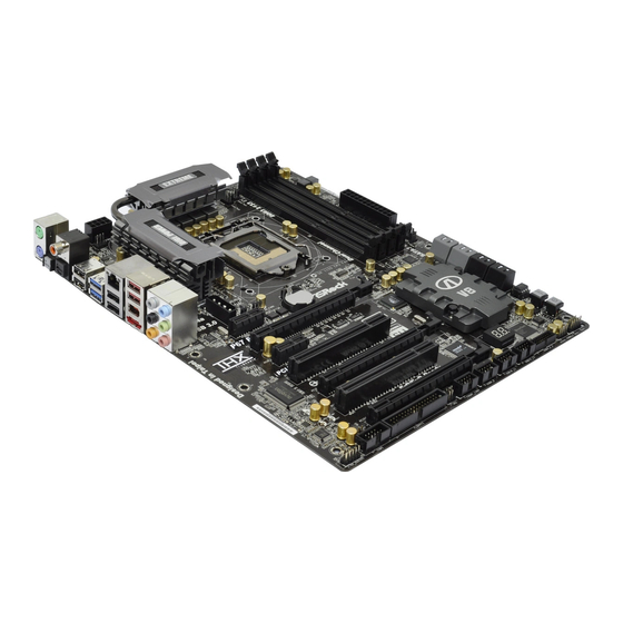
Page 12: Motherboard Layout
SATA3 Connector (SATA3_0, White) HDMI_SPDIF Header SATA3 Connector (SATA3_1, White) (HDMI_SPDIF1, White) SATA2 Connector (SATA2_2, Blue) PCI Express 2.0 x16 Slot (PCIE5, Blue) SATA2 Connector (SATA2_3, Blue) PCI Slot (PCI2) SATA2 Connector (SATA2_4, Blue) PCI Express 2.0 x16 Slot (PCIE4, Blue) -
Page 13: I/O Panel
Clear CMOS Switch (CLRCBTN) ** 9 Front Speaker (Lime) PS/2 Keyboard Port (Purple) * There are two LED next to the LAN port. Please refer to the table below for the LAN port LED indications. LAN Port LED Indications ACT/LINK... - Page 14 To enable Multi-Streaming function, you need to connect a front panel audio cable to the front panel audio header. After restarting your computer, you will nd “Mixer” tool on your system. Please select “Mixer ToolBox” , click “Enable playback multi-streaming”, and click “ok”.
-
Page 15: Installation
Chapter 2: Installation This is an ATX form factor (12.0" x 9.6", 30.5 x 24.4 cm) motherboard. Before you install the motherboard, study the con guration of your chassis to ensure that the motherboard ts into it. Make sure to unplug the power cord before installing or removing the motherboard. -
Page 16: Cpu Installation
Before you insert the 1155-Pin CPU into the socket, please check if the CPU surface is unclean or if there is any bent pin on the socket. Do not force to insert the CPU into the socket if above situation is found. Other- wise, the CPU will be seriously damaged. - Page 17 1155-Pin CPU For proper inserting, please ensure to match the two orientation key notches of the CPU with the two alignment keys of the socket. Step 3-3. Carefully place the CPU into the socket by using a purely vertical mo- tion.
-
Page 18: Installation Of Cpu Fan And Heatsink
Installation of CPU Fan and Heatsink This motherboard is equipped with 1155-Pin socket that supports Intel 1155-Pin CPU. Please adopt the type of heatsink and cooling fan compliant with Intel 1155- Pin CPU to dissipate heat. Before you installed the heatsink, you need to spray thermal interface material between the CPU and the heatsink to improve heat dis- sipation. -
Page 19: Installation Of Memory Modules (Dimm)
(the same brand, speed, size and chip-type) DDR3 DIMM pair in the slots of the same color. In other words, you have to install identical DDR3 DIMM pair in Dual Channel A (DDR3_ A1 and DDR3_B1;... -
Page 20: Installing A Dimm
DIMMs or the system components. Step 1. Unlock a DIMM slot by pressing the retaining clips outward. Step 2. Align a DIMM on the slot such that the notch on the DIMM matches the break on the slot. notch break... -
Page 21: Expansion Slots (Pci And Pci Express Slots)
2.6 Expansion Slots (PCI and PCI Express Slots) There are 2 PCI slots and 5 PCI Express slots on this motherboard. PCI slots: PCI slots are used to install expansion cards that have the 32-bit PCI interface. PCIE slots: PCIE1 / PCIE3 (PCIE x1 slot; White) is used for PCI Express cards with x1 lane width cards, such as Gigabit LAN card, SATA2 card, etc. -
Page 22: Tm Operation Guide
Operation Guide ® This motherboard supports NVIDIA and Quad SLI (Scalable Link Interface) technology that allows you to install up to three identical PCI Express x16 graphics ® ® cards. Currently, NVIDIA technology supports Windows XP / XP 64-bit / ®... - Page 23 Make sure ASRock SLI_Bridge_2S Card is rmly in place. ASRock SLI_Bridge_2S Card Step4. Connect a VGA cable or a DVI cable to the monitor connector or the DVI connector of the graphics card that is inserted to PCIE2 slot.
- Page 24 2.7.2 Driver Installation and Setup Install the graphics card drivers to your system. After that, you can enable the Multi- ® Graphics Processing Unit (GPU) feature in the NVIDIA nView system tray utility. Please follow the below procedures to enable the multi-GPU feature.
- Page 25 G. You can freely enjoy the bene t of SLI or Quad SLI feature. ® * SLI appearing here is a registered trademark of NVIDIA Technologies Inc., and is used only for identi cation or explanation and to the owners’ bene t, without intent to infringe.
-
Page 26: Crossfirex Tm Operation Guide
Graphics Processing Units (GPU) in a single PC. Combining a range of different operating modes with intelligent software design and an innovative interconnect mechanism, CrossFireX enables the highest possible level of performance and image quality in any 3D ®... - Page 27 Step 3. Connect the DVI monitor cable to the DVI connector on the Radeon graphics card on PCIE2 slot. (You may use the DVI to D-Sub adapter to convert the DVI connector to D-Sub interface, and then connect the D-Sub...
- Page 28 2.8.1.2 Installing Three CrossFireX -Ready Graphics Cards Step 1. Install one Radeon graphics card to PCIE2 slot. For the proper installation procedures, please refer to section “Expansion Slots”. Step 2. Install one Radeon graphics card to PCIE4 slot. For the proper installation procedures, please refer to section “Expansion Slots”.
- Page 29 Connect the DVI monitor cable to the DVI connector on the Radeon graph- ics card on PCIE2 slot. (You may use the DVI to D-Sub adapter to convert the DVI connector to D-Sub interface, and then connect the D-Sub monitor...
- Page 30 Install the CATALYST Control Center. Please check AMD website for de- tails. Step 4. Restart your computer. Step 5. Install the VGA card drivers to your system, and restart your computer. ® Then you will nd “ATI Catalyst Control Center” on your Windows taskbar. ATI Catalyst Control Center Step 6.
- Page 31 * CrossFireX appearing here is a registered trademark of ATI Technologies Inc., and is used only for identi cation or explanation and to the owners’ bene t, without intent to infringe. * For further information of ATI CrossFireX technology, please check AMD website for...
-
Page 32: Surround Display Feature
This motherboard supports Surround Display upgrade. With the external add-on PCI Express VGA cards, you can easily enjoy the bene ts of Surround Display feature. For the detailed instruction, please refer to the document at the following path in the Support CD: ..\ Surround Display Information... -
Page 33: Onboard Headers And Connectors
FDD connector (33-pin FLOPPY1) (see p.12 No. 33) the red-striped side to Pin1 Note: Make sure the red-striped side of the cable is plugged into Pin1 side of the connector. Serial ATAII Connectors These four Serial ATAII (SATAII) connectors support SATA data (SATA2_2: see p.12, No. - Page 34 DUMMY P+12 P-12 USB_PWR USB 3.0 Header Besides two default USB 3.0 IntA_P2_D+ IntA_P2_D- ports on the I/O panel, there is (19-pin USB3_2_3) IntA_P2_SSTX+ one USB 3.0 header on this (see p.12 No. 26) IntA_P2_SSTX- IntA_P2_SSRX+ motherboard. This USB 3.0...
- Page 35 Connect to the power status indicator on the chassis front panel. The LED is on when the system is operating. The LED keeps blinking when the sys- tem is in S1 sleep state. The LED is off when the system is in S3/S4 sleep state or powered off (S5).
- Page 36 Though this motherboard provides 4-Pin CPU fan (Quiet Fan) support, the 3-Pin CPU fan still can work successfully even without the fan speed control function. If you plan to connect the 3-Pin CPU fan to the CPU fan connector on this motherboard, please connect it to Pin 1-3.
- Page 37 Though this motherboard provides 8-pin ATX 12V power connector, it can still work if you adopt a traditional 4-pin ATX 12V power supply. To use the 4-pin ATX power supply, please plug your power supply along with Pin 1 and Pin 5.
- Page 38 Intall the Front USB 3.0 Panel into the 2.5” drive bay with six chassis screws. drive bay of the chassis. Step 5 Step 6 Plug the Front USB 3.0 cable into the USB 3.0 The Front USB 3.0 Panel is ready to use. header (USB3_2_3) on the motherboard.
-
Page 39: Smart Switches
2.12 Smart Switches The motherboard has three smart switches: power switch, reset switch and clear CMOS switch, allowing users to quickly turn on/off or reset the sytem clear the CMOS values. Power Switch Power Switch is a smart switch,... -
Page 40: Dr. Debug
2.13 Dr. Debug Dr. Debug is used to provide code information, which makes troubleshooting even easier. Please see the diagrams below for reading the Dr. Debug codes. SEC Phase Status Code Description 0x00 Not used Progress Codes 0x01 Power on. Reset type detection (soft/hard) - Page 41 0x5B reset PPI is not available 0x5C-0x5F Reserved for future AMI error codes S3 Resume Progress Codes 0xE0 S3 Resume is stared (S3 Resume PPI is called by the DXE IPL) 0xE1 S3 Boot Script execution 0xE2 Video repost 0xE3...
- Page 42 North Bridge DXE initialization is started 0x6A North Bridge DXE SMM initialization is started 0x6B North Bridge DXE initialization (North Bridge module speci c) 0x6C North Bridge DXE initialization (North Bridge module speci c) 0x6D North Bridge DXE initialization (North Bridge module speci c)
- Page 43 0xA7 SCSI Enable 0xA8 Setup Verifying Password 0xA9 Start of Setup 0xAA Reserved for ASL (see ASL Status Codes section below) 0xAB Setup Input Wait 0xAC Reserved for ASL (see ASL Status Codes section below) 0xAD Ready To Boot event...
- Page 44 System is waking up from the S3 sleep state 0x40 System is waking up from the S4 sleep state 0xAC System has transitioned into ACPI mode. Interrupt controller is in PIC mode 0xAA System has transitioned into ACPI mode. Interrupt controller is in APIC mode...
-
Page 45: Serial Ata (Sata) / Serial Ataii (Sataii) Hard Disks Installation
STEP 3: Connect one end of the SATA data cable to the motherboard’s SATAII con- nector. STEP 4: Connect the other end of the SATA data cable to the SATA / SATAII hard disk. 2.15 Serial ATA3 (SATA3) Hard Disks Installation ®... -
Page 46: Hot Plug And Hot Swap Functions For Sata / Sataii Hdds
SATA / SATAII HDD. What is Hot Swap Function? If SATA / SATAII HDDs are built as RAID 1 or RAID 5 then it is called “Hot Swap” for the action to insert and remove the SATA / SATAII HDDs while the system is still power-on and in working condition. -
Page 47: Sata / Sataii / Sata3 Hdd Hot Plug Feature And Operation Guide
1. Below operation procedure is designed only for our motherboard, which supports SATA / SATAII / SATA3 HDD Hot Plug. * The SATA / SATAII / SATA3 Hot Plug feature might not be supported by the chipset because of its limitation, the SATA / SATAII / SATA3 Hot Plug support information of our motherboard is indicated in the product spec on our website: www.asrock.com... - Page 48 SATA / SATAII / SATA3 HDD damage and data loss. Step 1 Unplug SATA data cable from SATA / SATAII / SATA3 HDD side. Step 2 Unplug SATA 15-pin power cable connector (Black) from SATA / SATAII / SATA3 HDD side.
-
Page 49: Driver Installation Guide
Then, the drivers compatible to your system can be auto-detected and listed on the support CD driver page. Please follow the order from up to bottom side to install those required drivers. Therefore, the drivers you install can work properly. -
Page 50: Setting Up A "Raid Ready" System
2.20.2 Setting Up a “RAID Ready” System You can also set up a “RAID Ready” system with a single SATA / SATAII / SATA3 hard disk. A “RAID Ready” system can be seamlessly upgraded to RAID 0, RAID 1 or RAID 5 at a later date by using RAID migration feature of Intel Rapid Storage. -
Page 51: Migrating A "Raid Ready" System To Raid
Rapid Storage Console which can be used to manage the RAID con guration. 7. After setting up a “RAID Ready” system as the above steps, you can follow the procedures of the next section to migrate the system to RAID 0, RAID 1 or RAID 2.20.3 Migrating a “RAID Ready”... -
Page 52: Installing Windows ® 7 / 7 64-Bit / Vista
Support CD, “Guide to SATA Hard Disks Installation and RAID Con guration”, which is lo- cated in the folder at the following path: .. \ RAID Installation Guide and the document in the support CD, “Guide to Intel Rapid Storage”, which is located in the folder at the follow- ing path: .. -
Page 53: Installing Windows ® 7 / 7 64-Bit / Vista
2 on page 49. ® STEP 3: Install Windows XP / XP 64-bit OS on your system. After making a SATA / SATAII / SATA3 driver diskette, you can start to install Win- ® ® dows XP / XP 64-bit on your system. At the beginning of Windows setup, press F6 to install a third-party AHCI driver. -
Page 54: Installing Windows ® 7 / 7 64-Bit / Vista
7 / 7 64-bit / Vista / Vista 64-bit OS on your SATA / SATAII / SATA3 HDDs without RAID functions, please follow below steps. Using SATA / SATAII / SATA3 HDDs with NCQ function STEP 1: Set Up BIOS. -
Page 55: Uefi Setup Utility
To exit the current screen or the UEFI SETUP UTILITY Exit Use < > key or < > key to choose among the selections on the menu bar, and then press <Enter> to get into the sub screen. You can also use the mouse to click your required item. -
Page 56: Navigation Keys
To save changes and exit the UEFI SETUP UTILITY <F10> To jump to the Exit Screen or exit the current screen <ESC> 3.2 Main Screen When you enter the UEFI SETUP UTILITY, the Main screen will appear and display the system overview. -
Page 57: Advanced Screen
3.3 Advanced Screen In this section, you may set the con gurations for the following items: CPU Con gu- ration, Integrated Clock Chip Con guration, DRAM Con guration, North Bridge Con- guration, South Bridge Con guration, Storage Con guration, Super IO Con gura- tion, Voltage Con guration, ACPI Con guration and USB Con guration. -
Page 58: Cpu Configuration
Vista / 7 and want to enable this function, please set this item to [Enabled]. This item will be hidden if the current CPU does not support Intel SpeedStep technology. Please note that enabling this function may reduce CPU voltage and lead to system stability or compatibility issue with some power supplies. - Page 59 CPU does not support Hyper-Threading technology. Active Processor Cores Use this item to select the number of cores to enable in each processor package. Con guration options: [All], [1] and [2]. The default value is [All].
-
Page 60: Integrated Clock Chip Con Guration
Local x2APIC Use this to enable or disable Local x2APIC. The default value is [Disabled]. Please be noted that some OS do not support this function. 3.3.2 Integrated Clock Chip Configuration DIV-1S Integrated Clock Control options. DIV-2S Integrated Clock Control options. -
Page 61: Dram Con Guration
3.3.3 DRAM Configuration Load XMP Setting Use this to load XMP setting. Con guration options: [Auto], [Pro le 1] and [Pro le 2]. The default value is [Auto]. DRAM Frequency If [Auto] is selected, the motherboard will detect the memory module(s) inserted and assigns appropriate frequency automatically. - Page 62 RAS to RAS Delay (tRRD) Use this item to change RAS to RAS Delay (tRRD) Auto/Manual setting. The default is [Auto]. Write to Read Delay (tWTR) Use this item to change Write to Read Delay (tWTR) Auto/Manual setting. The default is [Auto].
-
Page 63: North Bridge Con Guration
Use this to enable or disable Intel VT-d technology (Intel Virtualization Technology for Directed I/O). The default value of this feature is [Disabled]. Primary Graphics Adapter This allows you to select [PCI] or [PCI Express] as the boot graphic adapter priority. The default value is [PCI]. -
Page 64: South Bridge Con Guration
Select [Auto] or [Disabled] for the onboard HD Audio Front Panel. ACPI HPET Table Use this item to enable or disable ACPI HPET Table. The default value is [Enabled]. Please set this option to [Enabled] if you plan to use this ®... -
Page 65: Storage Configuration
3.3.6 Storage Configuration SATA Mode Use this to select SATA mode. Con guration options: [IDE Mode], [AHCI Mode] and [RAID Mode]. The default value is [IDE Mode]. AHCI (Advanced Host Controller Interface) supports NCQ and other new features that will improve SATA disk perfor- mance but IDE mode does not have these advantages. -
Page 66: Super Io Configuration
Use this item to enable or disable the onboard serial port. Serial Port Address Use this item to set the address for the onboard serial port or disable it. Con guration options: [Disabled], [3F8 / IRQ4], [2F8 / IRQ3], [3E8 / IRQ4], [2E8 / IRQ3]. -
Page 67: Voltage Con Guration
3.3.8 Voltage Configuration CPU Core Voltage Offset Use this to select CPU Core Voltage Offset. Con guration options: [Auto], [-0.005V] to [+0.500V]. The default value is [Auto]. CPU Load-Line Calibration Use this to select CPU Load-Line Calibration. Con guration options: [Disabled], [25%] to [100%]. -
Page 68: Acpi Configuration
Use this item to enable or disable PS/2 keyboard to turn on the system from the power-soft-off mode. PCI Devices Power On Use this item to enable or disable PCI devices to turn on the system from the power-soft-off mode. Ring-In Power On Use this item to enable or disable Ring-In signals to turn on the system from the power-soft-off mode. -
Page 69: Usb Configuration
3.3.10 USB Configuration USB 2.0 Controller Use this item to enable or disable the use of USB 2.0 controller. USB 3.0 Controller Use this item to enable or disable the use of USB 3.0 controller. Legacy USB Support Use this option to select legacy support for USB devices. There are four con guration options: [Enabled], [Auto], [Disabled] and [UEFI Setup Only]. -
Page 70: Hardware Health Event Monitoring Screen
3.4 Hardware Health Event Monitoring Screen In this section, it allows you to monitor the status of the hardware on your system, including the parameters of the CPU temperature, motherboard temperature, CPU fan speed, chassis fan speed, and the critical voltage. -
Page 71: Boot Screen
3.5 Boot Screen In this section, it will display the available devices on your system for you to con g- ure the boot settings and the boot priority. Boot Option Priorities Boot Option #1 Set the rst priority of the system boot device. -
Page 72: Security Screen
Boot Failure Guard Count Enable or disable the feature of Boot Failure Guard Count. 3.6 Security Screen In this section, you may set or change the supervisor/user password for the system. For the user password, you may also clear it. -
Page 73: Exit Screen
When you select this option, it will pop-out the following message, “Discard changes?” Select [OK] to discard all changes. Load UEFI Defaults Load UEFI default values for all the setup questions. F9 key can be used for this operation. User Default In this option, you are allowed to load and save three user defaults according to your own requirements. -
Page 74: Software Support
CD automatically displays the Main Menu if “AUTORUN” is enabled in your computer. If the Main Menu did not appear automatically, locate and double click on the le “ASSETUP.EXE” from the BIN folder in the Support CD to dis- play the menus. - Page 75 2. Set AHCI Mode in UEFI Setup Utility > Advanced > Storage Confi guration > SATA Mode. 3. Press F11 to launch boot menu at system POST. 4. Choose the item “UEFI:xxx“ to boot. (“xxx” is the device which contains ® your Windows installation fi...