ASROCK H61M-U3S3 User Manual
Hide thumbs
Also See for H61M-U3S3:
- Brochure & specs (7 pages) ,
- Manual (158 pages) ,
- User manual (158 pages)

Related Manuals for ASROCK H61M-U3S3


Summary of Contents for ASROCK H61M-U3S3
-
Page 1: User Manual
H61M/U3S3 User Manual Version 1.0 Published February 2011 Copyright©2011 ASRock INC. All rights reserved. -
Page 2: Copyright Notice
(including damages for loss of pro ts, loss of business, loss of data, interruption of business and the like), even if ASRock has been advised of the possibility of such damages arising from any defect or error in the manual or product. -
Page 3: Table Of Contents
2.12 Serial ATA3 (SATA3) Hard Disks Installation ..... 29 2.13 Hot Plug Function for SATA / SATAII HDDs ....30 2.14 Hot Plug Function for SATA3 HDDs ......30 2.15 SATA / SATAII / SATA3 HDD Hot Plug Feature and Operation Guide ............ - Page 4 3.4.5 Super IO Con guration ........47 3.4.6 ACPI Con guration..........48 3.4.7 USB Con guration ..........49 3.5 Hardware Health Event Monitoring Screen ....50 3.6 Boot Screen ..............51 3.7 Security Screen ............. 52 3.8 Exit Screen ..............53 4 Software Support ..........
-
Page 5: Introduction
ASRock’s commitment to quality and endurance. In this manual, chapter 1 and 2 contain introduction of the motherboard and step- by-step guide to the hardware installation. Chapter 3 and 4 contain the con guration guide to BIOS setup and information of the Support CD. -
Page 6: Specifi Cations
Specifications Platform - Micro ATX Form Factor: 9.6-in x 8.6-in, 24.4 cm x 21.8 cm - All Solid Capacitor design (100% Japan-made high-quality Conductive Polymer Capacitors) ® - Supports 2nd Generation Intel Core i7 / i5 / i3 in LGA1155 Package ®... - Page 7 - 1 x HDMI Port - 4 x Ready-to-Use USB 2.0 Ports - 2 x Ready-to-Use USB 3.0 Ports - 1 x RJ-45 LAN Port with LED (ACT/LINK LED and SPEED LED) - HD Audio Jack: Line in/Front Speaker/Microphone - 2 x SATA3 6.0 Gb/s connectors by ASMedia ASM1061, SATA3 support NCQ, AHCI and "Hot Plug"...
- Page 8 Overclocking may affect your system stability, or even cause damage to the components and devices of your system. It should be done at your own risk and expense. We are not responsible for possible damage caused by overclocking.
- Page 9 Your friends then can load the OC pro le to their own system to get the same OC settings. In IES (Intelligent Energy Saver), the voltage regulator can reduce the number of output phases to improve ef ciency when the CPU cores are idle without sacrificing computing performance.
- Page 10 ASRock AIWI is the world's rst utility to turn your iPhone/iPod touch as a game joystick to control your PC games. All you have to do is just to install the ASRock AIWI utility either from ASRock of cial website or ASRock software support CD to your motherboard, and also download the free AIWI Lite from App store to your iPhone/iPod touch.
- Page 11 EuP ready power supply are required. According to Intel’s suggestion, the EuP ready power supply must meet the standard of 5v standby power ef ciency is higher than 50% under 100 mA current consumption. For EuP ready power supply selection, we recommend you...
-
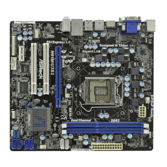
Page 12: Motherboard Layout
2 x 240-pin DDR3 DIMM Slots USB 2.0 Header (USB6_7, Blue) (Dual Channel: DDR3_A1, DDR3_B1, Blue) System Panel Header (PANEL1, White) Chassis Speaker Header (SPEAKER 1, White) 21 Infrared Module Header (IR1) ATX Power Connector (ATXPWR1) Clear CMOS Jumper (CLRCMOS1) -
Page 13: I/O Panel
** 5 Front Speaker (Lime) VGA/DVI-D Port Microphone (Pink) PS/2 Keyboard Port (Purple) * There are two LED next to the LAN port. Please refer to the table below for the LAN port LED indications. LAN Port LED Indications ACT/LINK SPEED... -
Page 14: Installation
Chapter 2: Installation This is a Micro ATX form factor (9.6" x 8.6", 24.4 x 21.8 cm) motherboard. Before you install the motherboard, study the con guration of your chassis to ensure that the motherboard ts into it. Make sure to unplug the power cord before installing or removing the motherboard. -
Page 15: Cpu Installation
Before you insert the 1155-Pin CPU into the socket, please check if the CPU surface is unclean or if there is any bent pin on the socket. Do not force to insert the CPU into the socket if above situation is found. Other- wise, the CPU will be seriously damaged. - Page 16 1155-Pin CPU For proper inserting, please ensure to match the two orientation key notches of the CPU with the two alignment keys of the socket. Step 3-3. Carefully place the CPU into the socket by using a purely vertical mo- tion.
-
Page 17: Installation Of Cpu Fan And Heatsink
Installation of CPU Fan and Heatsink This motherboard is equipped with 1155-Pin socket that supports Intel 1155-Pin CPU. Please adopt the type of heatsink and cooling fan compliant with Intel 1155- Pin CPU to dissipate heat. Before you installed the heatsink, you need to spray thermal interface material between the CPU and the heatsink to improve heat dis- sipation. -
Page 18: Installation Of Memory Modules (Dimm)
DIMMs or the system components. Step 1. Unlock a DIMM slot by pressing the retaining clips outward. Step 2. Align a DIMM on the slot such that the notch on the DIMM matches the break on the slot. notch break... -
Page 19: Expansion Slots (Pci And Pci Express Slots)
2.6 Expansion Slots (PCI and PCI Express Slots) There are 2 PCI slot and 2 PCI Express slots on this motherboard. PCI slots: PCI slots are used to install expansion cards that have the 32-bit PCI interface. PCIE slots: PCIE1 (PCIE x16 slot; Blue) is used for PCI Express x16 lane width graphics cards. -
Page 20: Dual Monitor And Surround Display Features
Dual Monitor Feature This motherboard supports dual monitor feature. With the internal VGA output sup- port (DVI-D, D-Sub and HDMI), you can easily enjoy the bene ts of dual monitor feature without installing any add-on VGA card to this motherboard. This mother-... - Page 21 Please refer to the following steps to set up a surround display environment: 1. Install the PCI Express VGA card on PCIE1 slot. Please refer to page 19 for proper expansion card installation procedures for details.
- Page 22 C. Click “OK” to save your change. D. Repeat steps A through C for the display icon identi ed by the number three and four. 6. Use Surround Display. Click and drag the display icons to positions representing the physical setup of your monitors that you would like to use.
-
Page 23: Asrock Smart Remote Installation Guide
The Multi-Angle CIR Receiver does not support Hot-Plug function. Please install it before you boot the system. * ASRock Smart Remote is only supported by some of ASRock motherboards. Please refer to ASRock website for the motherboard support list: http://www.asrock.com... -
Page 24: Jumpers Setup
Default Clear CMOS Note: CLRCMOS1 allows you to clear the data in CMOS. To clear and reset the system parameters to default setup, please turn off the computer and unplug the power cord from the power supply. After waiting for 15 seconds, use a jumper cap to short pin2 and pin3 on CLRCMOS1 for 5 seconds. -
Page 25: Onboard Headers And Connectors
2.10 Onboard Headers and Connectors Onboard headers and connectors are NOT jumpers. Do NOT place jumper caps over these headers and connectors. Placing jumper caps over the headers and connectors will cause permanent damage of the motherboard! Serial ATAII Connectors... - Page 26 HDA to function correctly. Please follow the instruction in our manual and chassis manual to install your system. 2. If you use AC’97 audio panel, please install it to the front panel audio header as below: A.
- Page 27 Connect to the power status indicator on the chassis front panel. The LED is on when the system is operating. The LED keeps blinking when the sys- tem is in S1 sleep state. The LED is off when the system is in S3/S4 sleep state or powered off (S5).
- Page 28 Though this motherboard provides 4-Pin CPU fan (Quiet Fan) support, the 3-Pin CPU fan still can work successfully even without the fan speed control function. If you plan to connect the 3-Pin CPU fan to the CPU fan connector on this motherboard, please connect it to Pin 1-3.
-
Page 29: Serial Ata (Sata) / Serial Ataii (Sataii) Hard Disks Installation
STEP 3: Connect one end of the SATA data cable to the motherboard’s SATAII con- nector. STEP 4: Connect the other end of the SATA data cable to the SATA / SATAII hard disk. 2.12 Serial ATA3 (SATA3) Hard Disks Installation This motherboard adopts ASMedia ASM1061 chipset that supports Serial ATA3 (SATA3) hard disks. -
Page 30: Hot Plug Function For Sata / Sataii Hdds
NOTE What is Hot Plug Function? If the SATA / SATAII HDDs are NOT set for RAID con guration, it is called “Hot Plug” for the action to insert and remove the SATA / SATAII HDDs while the system is still power-on and in working condition. -
Page 31: Sata / Sataii / Sata3 Hdd Hot Plug Feature And Operation Guide
1. Below operation procedure is designed only for our motherboard, which supports SATA / SATAII / SATA3 HDD Hot Plug. * The SATA / SATAII / SATA3 Hot Plug feature might not be supported by the chipset because of its limitation, the SATA / SATAII / SATA3 Hot Plug support information of our motherboard is indicated in the product spec on our website: www.asrock.com... - Page 32 SATA / SATAII / SATA3 HDD damage and data loss. Step 1 Unplug SATA data cable from SATA / SATAII / SATA3 HDD side. Step 2 Unplug SATA 15-pin power cable connector (Black) from SATA / SATAII / SATA3 HDD side.
-
Page 33: Driver Installation Guide
Then, the drivers compatible to your system can be auto-detected and listed on the support CD driver page. Please follow the order from up to bottom side to install those required drivers. Therefore, the drivers you install can work properly. -
Page 34: 64-Bit / Vista
7 / 7 64-bit / Vista / Vista 64-bit OS on your SATA / SATAII / SATA3 HDDs without RAID functions, please follow below steps. Using SATA / SATAII / SATA3 HDDs with NCQ function STEP 1: Set Up UEFI. -
Page 35: Uefi Setup Utility
To exit the current screen or the UEFI SETUP UTILITY Use < > key or < > key to choose among the selections on the menu bar, and then press <Enter> to get into the sub screen. You can also use the mouse to click your required item. -
Page 36: Navigation Keys
To save changes and exit the UEFI SETUP UTILITY <ESC> To jump to the Exit Screen or exit the current screen 3.2 Main Screen When you enter the UEFI SETUP UTILITY, the Main screen will appear and display the system overview. -
Page 37: Oc Tweaker Screen
Vista / 7 and want to enable this function, please set this item to [Enabled]. This item will be hid- den if the current CPU does not support Intel SpeedStep technology. Please note that enabling this function may reduce CPU voltage and lead to system stability or compatibility issue with some power supplies. - Page 38 Core Current Limit Use this item to add voltage when CPU is in Turbo mode. DRAM Timing Control DRAM Frequency If [Auto] is selected, the motherboard will detect the memory module(s) inserted and assigns appropriate frequency automatically. CAS# Latency (tCL) Use this item to change CAS# Latency (tCL) Auto/Manual setting.
- Page 39 Use this item to change ODT NOM (CHB) Auto/Manual setting. The de- fault is [Auto]. Voltage Control Power Saving Mode Use this to enable or disable Power Saving Mode. The default value is [Disabled]. CPU Core Voltage Offset Use this to select CPU Core Voltage Offset. The default value is [Auto].
-
Page 40: Advanced Screen
fi rst like MS-DOS or Windows . Just launch this tool and save the new UEFI fi le to your USB fl ash drive, fl oppy disk or hard drive, then you can update your UEFI only in a few clicks without preparing an additional fl... -
Page 41: Cpu Configuration
CPU does not support Hyper-Threading technology. Active Processor Cores Use this item to select the number of cores to enable in each processor package. Confi guration options: [All], [1], [2] and [3]. The default value is [All]. - Page 42 IA-32 Intel Architecture. An IA-32 processor with “No Execute (NX) Memory Protection” can prevent data pages from being used by malicious software to execute code. This option will be hidden if the current CPU does not support No-Excute Memory Protection.
-
Page 43: North Bridge Configuration
Device. The default value is [Disabled]. DVMT Mode Select Use this option to adjust DVMT mode. The default value is [DVMT Mode]. DVMT (Dynamic Video Memory Technology) is an architecture that offers breakthrough performance for the motherboard through effi cient memory utilization. - Page 44 DVMT Memory You are allowed to adjust the shared memory size in this item. Configuration options: [128MB], [256MB] and [Maximum]. The option [Maximum] only appears when you adopt the memory module with 1024MB or above.
-
Page 45: South Bridge Configuration
Mobile platforms support Deep S4/S5 in DC only and desktop platforms support Deep S4/S5 in AC only. Confi guration options: [Disabled], [Enabled in S5] and [Enabled in S4 and S5]. The default value is [Enabled in S5]. Onboard LAN This allows you to enable or disable the “Onboard LAN” feature. -
Page 46: Storage Configuration
3.4.4 Storage Configuration SATA Mode This item is used for SATA2 ports. Use this to select SATA mode. Confi gu- ration options: [IDE Mode], [AHCI Mode] and [Disabled]. The default value is [IDE Mode]. AHCI (Advanced Host Controller Interface) supports NCQ and other new features that will improve SATA disk perfor- mance but IDE mode does not have these advantages. -
Page 47: Super Io Configuration
Serial Port Use this item to enable or disable the onboard serial port. Serial Port Address Use this item to set the address for the onboard serial port. Confi guration options: [3F8 / IRQ4] and [3E8 / IRQ4]. CIR Controller Use this item to enable or disable the CIR controller. -
Page 48: Acpi Configuration
Use this item to enable or disable PS/2 keyboard to turn on the system from the power-soft-off mode. PCI Devices Power On Use this item to enable or disable PCI devices to turn on the system from the power-soft-off mode. Ring-In Power On Use this item to enable or disable Ring-In signals to turn on the system from the power-soft-off mode. -
Page 49: Usb Configuration
3.4.7 USB Configuration USB 2.0 Controller Use this item to enable or disable the use of USB 2.0 controller. USB 3.0 Controller Use this item to enable or disable the use of USB 3.0 controller. Legacy USB Support Use this option to select legacy support for USB devices. There are four confi... -
Page 50: Hardware Health Event Monitoring Screen
3.5 Hardware Health Event Monitoring Screen In this section, it allows you to monitor the status of the hardware on your system, including the parameters of the CPU temperature, motherboard temperature, CPU fan speed, chassis fan speed, and the critical voltage. -
Page 51: Boot Screen
3.6 Boot Screen In this section, it will display the available devices on your system for you to confi g- ure the boot settings and the boot priority. Setup Prompt Timeout This shows the number of seconds to wait for setup activation key. -
Page 52: Security Screen
3.7 Security Screen In this section, you may set or change the supervisor/user password for the system. For the user password, you may also clear it. -
Page 53: Exit Screen
When you select this option, it will pop-out the following message, “Discard changes?” Select [OK] to discard all changes. Load UEFI Defaults Load UEFI default values for all the setup questions. F9 key can be used for this operation. Launch EFI Shell from fi lesystem device Attempts to Launch EFI Shell application (Shell64.efi) from one of the... -
Page 54: Software Support
CD automatically displays the Main Menu if “AUTORUN” is enabled in your computer. If the Main Menu did not appear automatically, locate and double click on the fi le “ASSETUP.EXE” from the BIN folder in the Support CD to dis- play the menus. -
Page 55: Installing Os On A Hdd Larger Than 2Tb
2. Press <F2> or <Delete> at system POST. Set AHCI Mode in UEFI Setup Utility > Advanced > Storage Confi guration > SATA Mode. 3. Choose the item “UEFI:xxx“ to boot in UEFI Setup Utility > Boot > Boot Option #1. ®...