Table of Contents
Advertisement
Quick Links
Service and Maintenance Instructions
CONTENTS
SAFETY CONSIDERATIONS . . . . . . . . . . . . . . . . . . . 2
UNIT ARRANGEMENT AND ACCESS . . . . . . . . . . . . 3
General . . . . . . . . . . . . . . . . . . . . . . . . . . . . . . . . . . . . . 3
Routine Maintenance . . . . . . . . . . . . . . . . . . . . . . . . . 3
Filters . . . . . . . . . . . . . . . . . . . . . . . . . . . . . . . . . . . . . . 4
SUPPLY FAN (BLOWER) SECTION . . . . . . . . . . . . . . 4
Supply Fan (Direct-Drive) . . . . . . . . . . . . . . . . . . . . . . 4
Staged Air Volume . . . . . . . . . . . . . . . . . . . . . . . . . . 13
COOLING . . . . . . . . . . . . . . . . . . . . . . . . . . . . . . . . . . 13
Condenser Coil . . . . . . . . . . . . . . . . . . . . . . . . . . . . . 13
Recommendation . . . . . . . . . . . . . . . . . . . . . . . . . 13
Evaporator Coil . . . . . . . . . . . . . . . . . . . . . . . . . . . . . 15
Evaporator Coil Metering Devices . . . . . . . . . . . . . . 15
THERMOSTATIC EXPANSION VALVE (TXV) . . . . . 15
TXV Operation . . . . . . . . . . . . . . . . . . . . . . . . . . . . . . 15
Replacing TXV . . . . . . . . . . . . . . . . . . . . . . . . . . . . . . 15
Refrigerant System Pressure Access Ports . . . . . . 15
PURON (R-410A) REFRIGERANT . . . . . . . . . . . . . . . 16
Refrigerant Charge . . . . . . . . . . . . . . . . . . . . . . . . . . 16
COMPRESSOR . . . . . . . . . . . . . . . . . . . . . . . . . . . . . 27
Lubrication . . . . . . . . . . . . . . . . . . . . . . . . . . . . . . . . . 27
Replacing Compressor . . . . . . . . . . . . . . . . . . . . . . . 27
Compressor Rotation . . . . . . . . . . . . . . . . . . . . . . . . 27
Filter Drier . . . . . . . . . . . . . . . . . . . . . . . . . . . . . . . . . 27
Condenser-Fan Adjustment . . . . . . . . . . . . . . . . . . . 27
Troubleshooting Cooling System . . . . . . . . . . . . . . 28
CONVENIENCE OUTLETS . . . . . . . . . . . . . . . . . . . . 29
Convenience Outlets . . . . . . . . . . . . . . . . . . . . . . . . 29
Installing Weatherproof Cover . . . . . . . . . . . . . . . . . 29
Non-Powered Type . . . . . . . . . . . . . . . . . . . . . . . . . . 29
Unit-Powered Type . . . . . . . . . . . . . . . . . . . . . . . . . . 29
Duty Cycle . . . . . . . . . . . . . . . . . . . . . . . . . . . . . . . . . 30
Maintenance . . . . . . . . . . . . . . . . . . . . . . . . . . . . . . . 30
Fuse on Powered Type . . . . . . . . . . . . . . . . . . . . . . . 30
SMOKE DETECTORS . . . . . . . . . . . . . . . . . . . . . . . . 30
System . . . . . . . . . . . . . . . . . . . . . . . . . . . . . . . . . . . . 30
Controller . . . . . . . . . . . . . . . . . . . . . . . . . . . . . . . . . . 30
Smoke Detector Sensor . . . . . . . . . . . . . . . . . . . . . . 30
Smoke Detector Locations . . . . . . . . . . . . . . . . . . . . 31
Detector . . . . . . . . . . . . . . . . . . . . . . . . . . . . . . . . . 32
FIOP Smoke Detector Wiring and Response . . . . . 33
SENSOR AND CONTROLLER TESTS . . . . . . . . . . . 33
Sensor Alarm Test . . . . . . . . . . . . . . . . . . . . . . . . . . 33
Controller Alarm Test . . . . . . . . . . . . . . . . . . . . . . . . 33
Manufacturer reserves the right to discontinue, or change at any time, specifications or designs without notice and without incurring obligations.
Catalog No. 04-53480332-01
Single Package Rooftop Gas Heat/Electric Cooling Unit
Page
Printed in U.S.A.
Form 48FC-8-16-01SM
with Puron
®
7.5 to 15 Nominal Tons
Dirty Controller Test . . . . . . . . . . . . . . . . . . . . . . . . .33
Dirty Sensor Test . . . . . . . . . . . . . . . . . . . . . . . . . . . .34
Changing the Dirt Sensor Test . . . . . . . . . . . . . . . . .34
Remote Station Test . . . . . . . . . . . . . . . . . . . . . . . . .34
SD-TRK4 Remote Alarm Test Procedure . . . . . . . .34
Dirty Sensor Test Using an SD-TRK4 . . . . . . . . . . .35
Detector Cleaning . . . . . . . . . . . . . . . . . . . . . . . . . . .35
Indicators . . . . . . . . . . . . . . . . . . . . . . . . . . . . . . . . . .35
Troubleshooting . . . . . . . . . . . . . . . . . . . . . . . . . . . .36
PROTECTIVE DEVICES . . . . . . . . . . . . . . . . . . . . . . .36
Compressor Protection . . . . . . . . . . . . . . . . . . . . . . .36
Relief Device . . . . . . . . . . . . . . . . . . . . . . . . . . . . . . .37
Control Circuit, 24-V . . . . . . . . . . . . . . . . . . . . . . . . .37
GAS HEATING SYSTEM . . . . . . . . . . . . . . . . . . . . . .38
General . . . . . . . . . . . . . . . . . . . . . . . . . . . . . . . . . . . .38
Fuel Types and Pressures . . . . . . . . . . . . . . . . . . . .38
Flue Gas Passageways . . . . . . . . . . . . . . . . . . . . . . .39
Combustion-Air Blower . . . . . . . . . . . . . . . . . . . . . . .39
Burners and Igniters . . . . . . . . . . . . . . . . . . . . . . . . .40
Burner Ignition . . . . . . . . . . . . . . . . . . . . . . . . . . . . . .43
Orifice Replacement . . . . . . . . . . . . . . . . . . . . . . . . .43
Troubleshooting Heating System . . . . . . . . . . . . . .45
SYSTEMVU CONTROL SYSTEM . . . . . . . . . . . . . . . .47
SystemVu Interface . . . . . . . . . . . . . . . . . . . . . . . . . .47
Troubleshooting . . . . . . . . . . . . . . . . . . . . . . . . . .47
ECONOMIZER SYSTEMS . . . . . . . . . . . . . . . . . . . . .48
EconoMi$er2 . . . . . . . . . . . . . . . . . . . . . . . . . . . . . . .49
EconoMi$er IV (Field-Installed Accessory) . . . . . . .50
EconoMi$er X (Factory-Installed Option) . . . . . . . .57
PRE-START-UP/START-UP . . . . . . . . . . . . . . . . . . . .68
START-UP, GENERAL . . . . . . . . . . . . . . . . . . . . . . . .69
Unit Preparation . . . . . . . . . . . . . . . . . . . . . . . . . . . . .69
Additional Installation/Inspection . . . . . . . . . . . . . .69
Gas Piping . . . . . . . . . . . . . . . . . . . . . . . . . . . . . . . . .69
Return-Air Filters . . . . . . . . . . . . . . . . . . . . . . . . . . . .70
Outdoor-Air Inlet Screens . . . . . . . . . . . . . . . . . . . . .70
Compressor Mounting . . . . . . . . . . . . . . . . . . . . . . .70
Internal Wiring . . . . . . . . . . . . . . . . . . . . . . . . . . . . . .70
Refrigerant Service Ports . . . . . . . . . . . . . . . . . . . . .70
Compressor Rotation . . . . . . . . . . . . . . . . . . . . . . . .70
Cooling . . . . . . . . . . . . . . . . . . . . . . . . . . . . . . . . . . . .70
Main Burner . . . . . . . . . . . . . . . . . . . . . . . . . . . . . . . .71
Heating . . . . . . . . . . . . . . . . . . . . . . . . . . . . . . . . . . . .71
Ventilation (Continuous Fan) . . . . . . . . . . . . . . . . . .71
FASTENER TORQUE VALUES . . . . . . . . . . . . . . . . .71
START-UP, SYSTEMVU CONTROLS . . . . . . . . . . . .71
Pg 1
48FC**08-16
(R-410A) Refrigerant
11-23
Replaces: NEW
Advertisement
Table of Contents
Troubleshooting

Related Manuals for Carrier 48FC 08-16 Series


Summary of Contents for Carrier 48FC 08-16 Series
-
Page 1: Table Of Contents
48FC**08-16 Single Package Rooftop Gas Heat/Electric Cooling Unit with Puron ® (R-410A) Refrigerant 7.5 to 15 Nominal Tons Service and Maintenance Instructions CONTENTS Dirty Controller Test ......33 Dirty Sensor Test . -
Page 2: Safety Considerations
APPENDIX A — MODEL NUMBER NOMENCLATURE......72 WARNING APPENDIX B — PHYSICAL DATA ....73 APPENDIX C —... -
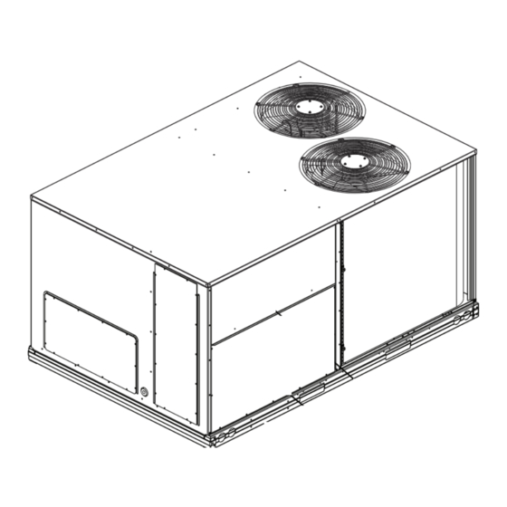
Page 3: Unit Arrangement And Access
UNIT ARRANGEMENT AND ACCESS General Figures 1-4 show general unit arrangement and access locations. Blower Access Panels Flue Control Box Hood Access Panel Filter Access Panel Fig. 4 — Blower Access Panel Location Indoor Coil Access Panel (size 16 units) Fig. -
Page 4: Filters
Air Filters and Screens Each unit is equipped with return air filters. If the unit has an econ- omizer, it will also have an outside air screen. If a manual outside air damper is added, an inlet air screen will also be present. Each of these filters and screens will need to be periodically re- placed or cleaned. - Page 5 Check the job specifications for the cfm (cubic feet per minute) and ESP (external static pressure) required. Using the chart on the Fan Speed Set Up labels (see Fig. 10), calculate the vdc from the cfm and ESP for the base. If installing any accessories listed at the bottom of the Set Motor Up Label, add accessory vdc to base unit vdc in upper por-...
- Page 6 ESP in. wg Factory Setting: Calculator 9.0 V 3000 Field Setting: 3250 Record field setting here 3500 3750 4000 Switch Range: 4250 4500 4.1 - 7.5 4750 10.0 6.9 - 8.7 5000 7.7 - 10.0 Field Accessories: Economizer * Overlap in A, B, C switch range designed for maximum field adjustment potential.
- Page 7 Units with SystemVu™ controls Use the DOWN arrow key highlight the UNIT CONFIG- URATIONS menu then press ENTER. On units equipped with the factory-installed SystemVu controller Highlight UNIT CONFIGURATIONS then press ENTER. the Fan Speed settings are accessed through the SystemVu interface. Highlight INDOOR FAN and then press ENTER.
- Page 8 TROUBLESHOOTING THE ECM MOTOR EcoBlue™ motors are designed with several built-in protections included in the motor software. If the motor detects a fault it will safely shut down. See Table 5, “Supply Fan Motor Logic and Safety Relays” on page 37 for a complete list. Troubleshooting the motor requires a voltmeter.
- Page 9 Removing the Motor and Fan Assembly NOTE: Due to press fit design of composite Rotor on Motor, it is highly recommended that any time a motor is replaced the fan ro- tor is replaced as well. The rest of the assembly may be reused. See Fig.
- Page 10 Disassembling Standard/Medium Motor and Fan Assembly Disassembling High Static Motor and Fan Assembly See Fig. 14. See Fig. 15. NOTE: Refer to “Model Number Nomenclature” on page 72, NOTE: Refer to “Model Number Nomenclature” on page 72, position 10 for specific unit requirements. position 10 for specific unit requirements.
- Page 11 Reassembly of Standard/Medium Motor and Fan Assembly Reassembly of High Static Motor and Fan Assembly See Fig. 16. See Fig. 17. NOTE: Refer to “Model Number Nomenclature” on page 72, NOTE: Refer to “Model Number Nomenclature” on page 72, position 10 for specific unit requirements. position 10 for specific unit requirements.
- Page 12 Reinstalling Motor and Fan Assembly See Fig. 18. Align motor harness/grommet at ~7 o’clock (facing installer) and align the bottom flats on right and left sides of fan stator with fan deck ribs. Drop fan assembly down into fan deck opening and slide back until aluminum stator is under the rear fan deck brackets.
-
Page 13: Staged Air Volume
PERIODIC CLEAN WATER RINSE Staged Air Volume All 48FC-08-16 units with EcoBlue™ technology come factory A periodic clean water rinse is very beneficial for coils that are ap- set to automatically adjust the indoor fan motor speed in sequence plied in coastal or industrial environments. However, it is very im- with the unit’s ventilation, cooling, and heating operation. - Page 14 Top Panel Support (Field- Supplied) Center Baffle Fig. 20 — Propping Up Top Panel Remove the compressor access panel to access the lower coil clip. The condenser coil corner post may also be removed. Fig. 22 — Separating Coil Sections Remove the screws from both sides of the 4 coil retaining (Top View) clips on the hairpin end of the coil tube sheets.
-
Page 15: Evaporator Coil
Thoroughly apply Totaline environmentally balanced coil The suction pressure at the outlet of the evaporator coil is cleaner solution to all coil surfaces including finned area, tube transferred through the external equalizer tube to the sheets and coil headers. underside of the diaphragm. Hold garden sprayer nozzle close to finned areas and apply The pin is spring loaded, which exerts pressure on the under- cleaner with a vertical, up-and-down motion. -
Page 16: Puron (R-410A) Refrigerant
I N S U L A T I O N C O V E R R E M O V E D fer to Carrier GTAC2-5 Charging, Recovery, Recycling and Rec- S U C T I O N L I N E lamation training manual and the following procedures. - Page 17 COOLING CHARGING CHARTS 7.5 Ton Entry Tier R-410A Charging Chart (Unit must have both compressors and outdoor fans on high speed) 59.9 Add Charge if Above Curve 48.8 37.7 26.6 Remove Charge if Below the Curve 15.5 -6.7 1034 1379 1723 2068 2413...
- Page 18 COOLING CHARGING CHARTS 8.5 Ton Entry Tier R-410A Charging Chart (Unit must have both compressors and outdoor fans on high speed) 59.9 Add Charge if Above Curve 48.8 37.7 26.6 Remove Charge if Below the Curve 15.5 -6.7 1034 1379 1723 2068 2413...
- Page 19 COOLING CHARGING CHARTS 10 Ton Entry Tier R-410A Charging Chart (Unit must have both compressors and outdoor fans on high speed) 59.9 Add Charge if Above Curve 48.8 37.7 26.6 Remove Charge if Below the Curve 15.5 -6.7 1034 1379 1723 2068 2413...
- Page 20 COOLING CHARGING CHARTS 12.5 Ton Entry Tier R-410A Charging Chart (Unit must have both compressors and outdoor fans on high speed) 59.9 Add Charge if Above Curve 48.8 37.7 26.6 Remove Charge if Below the Curve 15.5 -6.7 1034 1379 1723 2068 2413...
- Page 21 COOLING CHARGING CHARTS 15 Ton Entry Tier R-410A Charging Chart (Unit must have both compressors and outdoor fans on high speed) 59.9 Add Charge if Above Curve 48.8 37.7 26.6 Remove Charge if Below the Curve 15.5 -6.7 1034 1379 1723 2068 2413...
- Page 22 COOLING CHARGING CHARTS 7.5 Ton 48/50 FC / 582/559 / RGV/RAV (Unit must run in Subcooling mode) 59.9 Add Charge if Above Curve 48.8 37.7 26.6 Remove Charge if Below the Curve 15.5 -6.7 1034 1379 1723 2068 2413 2758 3102 3447 3792...
- Page 23 COOLING CHARGING CHARTS 8.5 Ton 48/50 FC / 582/559 / RGV/RAV (Unit must run in Subcooling mode) 59.9 Add Charge if Above Curve 48.8 37.7 26.6 15.5 Remove Charge if Below the Curve -6.7 1034 1379 1723 2068 2413 2758 3102 3447 3792...
- Page 24 COOLING CHARGING CHARTS 10 Ton 48/50 FC / 582/559 / RGV/RAV (Unit must run in Subcooling mode) 59.9 Add Charge if Above Curve 48.8 37.7 26.6 Remove Charge if Below the Curve 15.5 -6.7 1034 1379 1723 2068 2413 2758 3102 3447 3792...
- Page 25 COOLING CHARGING CHARTS 12.5 Ton 48/50 FC / 582/559 / RGV/RAV (Unit must run in Subcooling mode) 59.9 Add Charge if Above Curve 48.8 37.7 26.6 Remove Charge if Below the Curve 15.5 -6.7 1034 1379 1723 2068 2413 2758 3102 3447 3792...
- Page 26 COOLING CHARGING CHARTS 15 Ton 48/50 FC / 582/559 / RGV/RAV (Unit must run in Subcooling mode) 59.9 Add Charge if Above Curve 48.8 37.7 26.6 Remove Charge if Below the Curve 15.5 -6.7 1034 1379 1723 2068 2413 2758 3102 3447 3792...
-
Page 27: Compressor
COMPRESSOR Compressor Rotation Lubrication The compressor is charged with the correct amount of oil at the CAUTION factory. EQUIPMENT DAMAGE HAZARD Failure to follow this caution can result in premature wear and CAUTION damage to equipment. Scroll compressors can only compress refrigerant if UNIT DAMAGE HAZARD rotating in the right direction. -
Page 28: Troubleshooting Cooling System
Troubleshooting Cooling System Refer to Table 2 for additional troubleshooting topics. Table 2 — Troubleshooting SYMPTOM CAUSE SOLUTION Power failure. Call power company. Fuse blown or circuit breaker tripped. Replace fuse or reset circuit breaker. Determine root cause. Defective thermostat, contactor, transformer. Replacement component. -
Page 29: Convenience Outlets
Press the gasket over the screw heads. Slip the backing CONVENIENCE OUTLETS plate over the screw heads at the keyhole slots and align with the gasket; tighten the two screws until snug (do not over-tighten). WARNING Mount the weatherproof cover to the backing plate as ELECTRICAL OPERATION HAZARD shown in Fig. -
Page 30: Duty Cycle
SMOKE DETECTORS Smoke detectors are available as factory-installed options on 48FC models. Smoke detectors may be specified for supply air only, for return air without or with economizer, or in combination of supply air and return air. Return air smoke detectors are ar- ranged for vertical return configurations only. -
Page 31: Smoke Detector Locations
Air is introduced to the duct smoke detector sensor’s sensing chamber through a sampling tube that extends into the HVAC duct and is directed back into the ventilation system through a (shorter) Supply Air exhaust tube. Smoke Detector The difference in air pressure between the two tubes pulls the sam- pled air through the sensing chamber. -
Page 32: Completing Installation Of Return Air Smoke
Completing Installation of Return Air Smoke Detector Use the following steps to complete the installation of the return air smoke detector. Unscrew the two screws holding the return air sensor detector plate. See Fig. 45. Save the screws. Flexible Exhaust Tubes Screws Return Air Smoke Detector... -
Page 33: Fiop Smoke Detector Wiring And Response
SENSOR ALARM TEST PROCEDURE FIOP Smoke Detector Wiring and Response Hold the test magnet where indicated on the side of the ALL UNITS sensor housing for seven seconds. The FIOP smoke detector is configured to automatically shut Verify that the sensor’s Alarm LED turns on. down all unit operations when a smoke condition is detected. -
Page 34: Dirty Sensor Test
Reset the sensor by removing the test magnet then holding it against the sensor housing again until the sensor’s Alarm IMPORTANT: Failure to follow this ALERT can result in LED turns off (approximately 2 seconds). an unnecessary evacuation of the facility. Pressing the controller’s test/reset switch for longer than seven Remote Station Test seconds will put the duct detector into the alarm state and... -
Page 35: Dirty Sensor Test Using An Sd-Trk4
ALARM STATE The smoke detector enters the alarm state when the amount of IMPORTANT: Failure to follow this ALERT can result in smoke particulate in the sensor’s sensing chamber exceeds the an unnecessary evacuation of the facility. alarm threshold value. (See Table 4.) Upon entering the alarm Holding the test magnet to the target area for longer than seven state: seconds will put the detector into the alarm state and activate... -
Page 36: Troubleshooting
RESETTING ALARM AND TROUBLE CONDITION TRIPS PROTECTIVE DEVICES Manual reset is required to restore smoke detector systems to Nor- Compressor Protection mal operation. For installations using two sensors, the duct smoke detector does not differentiate which sensor signals an alarm or OVERCURRENT trouble condition. -
Page 37: Relief Device
LOW PRESSURE SWITCH CONDENSER FAN MOTOR PROTECTION The system is protected against a loss of charge and low evapora- The condenser fan motor is internally protected against tor coil loading condition by a low pressure switch located on the over-temperature. suction line near the compressor. -
Page 38: Gas Heating System
GAS HEATING SYSTEM Fuel Types and Pressures NATURAL GAS General The heat exchanger system consists of a gas valve feeding multi- The 48FC unit is factory-equipped for use with natural gas (NG) ple in-shot burners off a manifold. The burners fire into matching fuel at elevation under 2000 ft (610 m). -
Page 39: Flue Gas Passageways
SUPPLY PRESSURE SWITCH This switch also prevents operation when the propane tank lev- el is low, which can result in gas with a high concentration of The LP conversion kit includes a supply low pressure switch. The impurities, additives, and residues that have settled to the bot- switch contacts (from terminal C to terminal NO) will open the gas tom of the tank. -
Page 40: Burners And Igniters
Heater Tube Assembly Seal Strips, Sponge Rubber Regulator Gasket Regulator Retainer Vestibule Plate Flue Cover Assembly Inducer Fan-motor Assembly Burner Assembly Fig. 56 — Heat Exchanger Assembly REMOVAL AND REPLACEMENT OF GAS TRAIN Burners and Igniters See Fig. 52, 56, 58, and 59. Shut off manual gas valve. - Page 41 Heat Exchanger Support Rack Gas Limit Switch Heat Exchanger Burner Partition Panel Cover Panel Unit Center Post Fig. 58 — Heat Exchanger Access - Internal Panels, Center Post and HX Rack Locations CLEANING AND ADJUSTMENT Integrated Gas Remove burner rack from unit as described in “Removal Controller (IGC) and Replacement of Gas Train”...
- Page 42 Disconnect a gas pipe union and remove the gas manifold 12. Remove the nuts holding the heat exchanger support rack with the gas valve. to the fan deck. Remove the two screws attaching the burner rack to the 13. Remove the heat exchanger from the unit. vestibule plate (see Fig.
-
Page 43: Burner Ignition
GAS VALVE LED (light-emitting diode). A single LED (see Fig. 63) on the IGC provides a visual display of operational or sequential prob- All three-phase models are equipped with 2-stage gas valves. lems when the power supply is uninterrupted. When a break in See Fig. - Page 44 RED LED - STATUS Fig. 63 — Integrated Gas Control (IGC) Board...
-
Page 45: Troubleshooting Heating System
MINIMUM HEATING ENTERING AIR TEMPERATURE Thermostat When operating on first stage heating, the minimum temperature of air entering the dimpled heat exchanger is 50°F continuous and 45°F intermittent for standard heat exchangers and 40°F continuous and 35°F intermittent for stainless steel heat ex- OALT changers. - Page 46 Table 12 — IGC Board LED Alarm Codes ACTION TAKEN BY FLASH DESCRIPTION RESET METHOD PROBABLE CAUSE CONTROL CODE Normal Operation — — — Hardware Failure No gas heating. Loss of power to the IGC. Check 5 amp fuse — on IGC, power to unit, 24V circuit breaker, transformer, and wiring to the IGC.
-
Page 47: Systemvu Control System
Through the SystemVu interface, the user can access all of the in- The SystemVu control system is fully communicating and cable- puts and outputs to check on their values and status, configure op- ready for connection to the Carrier Comfort Network (CCN), ®... -
Page 48: Economizer Systems
ECONOMIZER SYSTEMS The unit may be equipped with a factory-installed or accessory Outside Air (field-installed) economizer system. Three types are available: Temperature Sensor two with logic control systems (EconoMi$er X and ® Low Ambient EconoMi$er IV) and one without a control system EconoMi$er IV Sensor (EconoMi$er2). -
Page 49: Economi$Er2
EconoMi$er2 IMPORTANT: The optional EconoMi$er 2 does not ® include a controller. The EconoMi$er2 is operated by a 4 mA to 20 mA signal from an existing field-supplied controller. See Fig. 69 for wiring information. BLACK Transformer Ground BLUE 500 OHM Resistor VIOLET PINK... -
Page 50: Economi$Er Iv (Field-Installed Accessory)
EconoMi$er IV (Field-Installed Accessory) IMPORTANT: For 48FC-08-16 rooftop units EconoMi$er IV is only available as a field-installed accessory. ECONOMI$ER IV STANDARD SENSORS Troubleshooting instructions are enclosed. A functional view of the EconoMi$er ® IV accessory is shown in Fig. 70. Typical set- tings, sensor ranges, and jumper positions are also shown. - Page 51 Table 13 — EconoMi$er IV Input/Output Logic INPUTS OUTPUTS Demand Enthalpy Compressor N Terminal Controlled Ventilation Outdoor Return Stage 1 Stage 2 Occupied Unoccupied (DCV) High (Free Cooling Minimum position Closed LED Off) Below Set (DCV LED Off) Modulating (between Modulating (between min.
- Page 52 Outdoor Air Lockout Sensor DIP Switch Changeover The EconoMi$er IV is equipped with an ambient temperature Position Temperature lockout switch located in the outdoor airstream which is used to lock out the compressors below a 42°F (6°C) ambient tem- 48°F perature.
- Page 53 Horizontal Economizer Barometric Relief Vertical Economizer Barometric Relief Horizontal Economizer Barometric Relief Flow Vertical Economizer Barometric Relief Flow 2500 2500 2000 2000 1500 1500 1000 1000 0.00 0.05 0.10 0.15 0.20 0.25 0.30 0.00 0.05 0.10 0.15 0.20 0.25 0.30 Return Duct Static Pressure (in.
- Page 54 (29) (32) (35) (38) (41) (43) EconoMi$er IV CONTROL POINT Controller CONTROL APPROX. °F (°C) CURVE AT 50% RH (27) 73 (23) 70 (21) EconoMi$er IV 67 (19) 63 (17) (24) (21) (18) Grommet (16) (13) (10) Return Air Sensor Return Duct (Field-Provided) HIGH LIMIT...
- Page 55 Exhaust Set Point Adjustment Damper Movement The exhaust set point will determine when the exhaust fan runs Damper movement from full open to full closed (or vice versa) based on damper position (if accessory power exhaust is in- takes 2-1/2 minutes. stalled).
- Page 56 Remove 620-ohm resistor across SO and +. The Free Cool Use setting 1 or 2 for Carrier equipment: LED should turn off. Press Clear and Mode buttons. Hold at least 5 seconds Return EconoMi$er IV settings and wiring to normal after until the sensor enters the Edit mode.
-
Page 57: Economi$Er X (Factory-Installed Option)
Turn the DCV Maximum Position potentiometer to fully CCW. The actuator should drive fully closed. Turn the Minimum Position potentiometer to mid-point. The actuator should drive to between 20 and 80% open. Turn the Minimum Position Potentiometer fully CW. The actuator should drive fully open. - Page 58 SPECIFICATIONS Temperature and Humidity, C7400S1000 (optional) S-Bus; 2-wire (18 to 22 AWG) W7220 Economizer Module Temperature: range –40°F to 150°F (–40°C to 65°C) The module is designed for use with 2 to 10 vdc or bus communi- cating actuator. The module includes terminals for CO sensor, Temperature accuracy –0°F/+2°F Mixed Air sensor, and an Outdoor Dry Bulb sensor.
- Page 59 Table 16 — Economizer Module - Right Hand Terminal Blocks LABEL TYPE DESCRIPTION Top Right Terminal Blocks AUX2 I 24 vac IN The first terminal is not used. Shut Down (SD) or HEAT (W) AUX2- Conventional only 24 vac IN Heat Pump Changeover (O-B) in Heat E-GND Pump mode.
- Page 60 Keypad Table 17 — HH57AC081 Sensor Wiring Terminations The four navigation buttons (see Fig. 86) are used to scroll through the menus and menu items, select menu items, and to TERMINAL TYPE DESCRIPTION change parameter and configuration settings. NUMBER LABEL To use the keypad when working with menus: S-BUS Communications...
- Page 61 Setup and Configuration Before being placed into service, the W7220 economizer module IMPORTANT: Table 19 illustrates the complete hierarchy. must be setup and configured for the installed system. Your menu parameters may be different depending on your configuration. For example, if you do not have a DCV (CO ) sensor, then IMPORTANT: During setup, the economizer module is live none of the DCV parameters appear and only MIN POS will...
- Page 62 Table 19 — W7220 Menu Structure (cont) PARAMETER PARAMETER MENU PARAMETER DEFAULT RANGE AND NOTES VALUE INCREMENT DEMAND CONTROLLED VENTILATION STATUS DCV STATUS ON/OFF Displays ON if above setpoint and OFF if below setpoint, and ONLY if a CO sensor is connected. DAMPER OUT 2.0v 2.0 to 10.0v...
- Page 63 Table 19 — W7220 Menu Structure (cont) PARAMETER PARAMETER MENU PARAMETER DEFAULT RANGE AND NOTES VALUE INCREMENT DCV MAXIMUM DAMPER POSITION AT HIGH SPEED. Only displays if unit is set for 2 speed or 3 speed with 1 heat and 2 cool. IF using 2 VENTMAX H 4.4 V 2 to 10 vdc...
- Page 64 Table 19 — W7220 Menu Structure (cont) PARAMETER PARAMETER MENU PARAMETER DEFAULT RANGE AND NOTES VALUE INCREMENT 35°F to 55°F SUPPLY AIR TEMPERATURE LOW LIMIT (2°C to 13°C); MA LO SET 45°F Temperature to achieve Freeze Protection (close damper and alarm if Incremented by temperature falls below setup value).
- Page 65 Table 19 — W7220 Menu Structure (cont) PARAMETER PARAMETER MENU PARAMETER DEFAULT RANGE AND NOTES VALUE INCREMENT SENSOR ERROR CO2 SENS ERR sensor has failed, gone out of range or become disconnected - check wiring then replace sensor if the alarm continues. OA SYLK T ERR OUTSIDE AIR S-BUS SENSOR ERROR Outdoor air enthalpy sensor has failed or become disconnected - check...
- Page 66 Enthalpy Settings Table 20 — Fan Speed When the OA temperature, enthalpy and dew point are below the respective set points, the Outdoor Air can be used for economizing. STATE FAN SPEED Figure 87 shows the new single enthalpy boundaries in the W7220. There are 5 boundaries (set points ES1 through ES5), which are de- fined by dry bulb temperature, enthalpy and dew point.
- Page 67 Table 22 — Economizer Operation - FAN TYPE = 2 SPEED INPUTS OUTPUTS DEMAND DAMPER POSITION OUTSIDE AIR FAN SPEED CONTROLLED COOL COOL COOL COOL GOOD TO (reference VENTILATION (HEAT ON) Y1-IN Y2-IN Y1-OUT Y2-OUT OCCUPIED UNOCCUPIED ECONOMIZE only) (DCV) HIGH MIN POS H Closed...
-
Page 68: Pre-Start-Up/Start-Up
CHECKOUT TROUBLESHOOTING Inspect all wiring connections at the economizer module’s termi- Alarms nals, and verify compliance with the installation wiring diagrams. The economizer module provides alarm messages that display on For checkout, review the Status of each configured parameter and the 2-line LCD. -
Page 69: Start-Up, General
START-UP, GENERAL WARNING Unit Preparation Make sure that unit has been installed in accordance with installa- ELECTRICAL OPERATION HAZARD tion instructions and applicable codes. Failure to follow this warning could result in personal injury or In addition to the base unit start-up (unit with electro-mechanical death. -
Page 70: Return-Air Filters
Internal Wiring Check all electrical connections in unit control boxes. Tighten as WARNING required. If the information in this manual is not followed exactly, a fire Refrigerant Service Ports or explosion may result causing property damage, personal in- Each unit system has two 1/4-in. SAE flare (with check valves) jury or loss of life. -
Page 71: Main Burner
period, the evaporator-fan off delay will increase by 15 seconds. Main Burner A maximum of 9 trips can occur, extending the evaporator-fan Main burners are factory set and should require no adjustment. off delay to 180 seconds. To check ignition of main burners and heating controls, move To restore the original default value, reset the power to the unit. - Page 72 APPENDIX A — MODEL NUMBER NOMENCLATURE Position: 9 10 11 12 13 14 15 16 17 18 Example: Unit Heat Type Packaging Compliance 48 — Gas Heat Packaged Rooftop 0 = Standard 1 = LTL Model Series - WeatherMaker ® FC —...
- Page 73 APPENDIX B — PHYSICAL DATA 48FC*(M,N)08-09 — 7.5 Ton to 8.5 Ton — Physical Data UNIT 48FC*M08 48FC*N08 48FC*M09 48FC*N09 NOMINAL CAPACITY (tons) REFRIGERATION SYSTEM No. Circuits / No. Comp. / Type 1 / 2 / Scroll 1 / 2 / Scroll 1 / 2 / Scroll 1 / 2 / Scroll Puron...
- Page 74 APPENDIX B — PHYSICAL DATA (cont) 48FC*(M,N)12-14 — 10 Ton to 12.5 Ton — Physical Data UNIT 48FC*M12 48FC*N12 48FC*M14 48FC*N14 NOMINAL CAPACITY (tons) 12.5 12.5 REFRIGERATION SYSTEM No. Circuits / No. Comp. / Type 1 / 2 / Scroll 1 / 2 / Scroll 1 / 2 / Scroll 1 / 2 / Scroll...
- Page 75 APPENDIX B — PHYSICAL DATA (cont) 48FC*(M,N)16 — 15 Ton — Physical Data UNIT 48FC*M16 48FC*N16 NOMINAL CAPACITY (tons) REFRIGERATION SYSTEM No. Circuits / No. Compressors / Type 1 / 2 / Scroll 1 / 2 / Scroll Puron ® (R-410A) Charge (lb-oz) 24-0 34-0...
- Page 76 APPENDIX C — GAS HEAT DATA 48FC*(M,N)08-16 — 7.5 Ton to 15.0 Ton 48FC UNIT 48FC**08 48FC**09 48FC**12 48FC**14 48FC**16 Nominal Capacity (tons) 12.5 Gas Connection No. of Gas Valves Natural Gas Supply Line Pressure 4-13 / 0.18-0.47 4-13 / 0.18-0.47 4-13 / 0.18-0.47 4-13 / 0.18-0.47 4-13 / 0.18-0.47...
- Page 77 APPENDIX D — FAN PERFORMANCE GENERAL FAN PERFORMANCE NOTES For more information on the performance limits of the fan motors, see the application data section of this book. Interpolation is permissible. Do not extrapolate. The EPACT (Energy Policy Act of 1992) regulates energy External static pressure is the static pressure difference requirements for specific types of indoor fan motors.
- Page 78 APPENDIX D — FAN PERFORMANCE (cont) 48FCFM08 — 7.5 Ton Vertical Supply (rpm - bhp) AVAILABLE EXTERNAL STATIC PRESSURE (in. wg) 2250 1045 0.43 1166 0.60 1273 0.78 1372 0.97 1463 1.18 2440 1111 0.51 1226 0.69 1329 0.88 1424 1.08 1512 1.30...
- Page 79 APPENDIX D — FAN PERFORMANCE (cont) 48FCFM08 — High Static — 7.5 Ton Vertical Supply (rpm - vdc) AVAILABLE EXTERNAL STATIC PRESSURE (in. wg) 2250 1045 1166 1273 1372 1463 2440 1111 1226 1329 1424 1512 2625 1178 1288 1387 1478 1564 2810...
- Page 80 APPENDIX D — FAN PERFORMANCE (cont) 48FCFM09 — 8.5 Ton Vertical Supply (rpm - bhp) AVAILABLE EXTERNAL STATIC PRESSURE (in. wg) 2550 1091 0.48 1198 0.63 1298 0.81 1391 0.99 1478 1.19 2760 1164 0.58 1264 0.74 1359 0.92 1448 1.11 1532 1.31...
- Page 81 APPENDIX D — FAN PERFORMANCE (cont) 48FCFM09 — High Static — 8.5 Ton Vertical Supply (rpm - vdc) AVAILABLE EXTERNAL STATIC PRESSURE (in. wg) 2550 1091 1198 1298 1391 1478 2760 1164 1264 1359 1448 1532 2975 1238 1332 1422 1507 1588 3190...
- Page 82 APPENDIX D — FAN PERFORMANCE (cont) 48FCFM12 — 10 Ton Vertical Supply (rpm - bhp) AVAILABLE EXTERNAL STATIC PRESSURE (in. wg) 3000 1266 0.74 1360 0.92 1449 1.12 1534 1.32 1613 1.54 3250 1357 0.91 1444 1.09 1528 1.29 1608 1.51 1684 1.73...
- Page 83 APPENDIX D — FAN PERFORMANCE (cont) 48FCFM12 — High Static — 10 Ton Vertical Supply (rpm - vdc) AVAILABLE EXTERNAL STATIC PRESSURE (in. wg) 3000 1266 1360 1449 1534 1613 3250 1357 1444 1528 1608 1684 3500 1448 1530 1609 1685 1758 3750...
- Page 84 APPENDIX D — FAN PERFORMANCE (cont) 48FCFM14 — 12.5 Ton Vertical Supply (rpm - bhp) AVAILABLE EXTERNAL STATIC PRESSURE (in. wg) 3750 1320 1.21 1416 1.49 1503 1.79 1583 2.09 1657 2.39 4060 1414 1.48 1504 1.78 1587 2.09 1664 2.41 1736 2.74...
- Page 85 APPENDIX D — FAN PERFORMANCE (cont) 48FCFM14 — High Static — 12.5 Ton Vertical Supply (rpm - vdc) AVAILABLE EXTERNAL STATIC PRESSURE (in. wg) 3750 1320 1416 1503 1583 1657 4060 1414 1504 1587 1664 1736 4375 1509 1594 1673 1747 1817 4690...
- Page 86 APPENDIX D — FAN PERFORMANCE (cont) 48FCFM16 — 15 Ton Vertical Supply (rpm - bhp) AVAILABLE EXTERNAL STATIC PRESSURE (in. wg) 4500 1251 1.02 1332 1.23 1412 1.47 1491 1.73 1569 2.02 4875 1343 1.26 1417 1.48 1491 1.72 1565 1.99 1637 2.28...
- Page 87 APPENDIX D — FAN PERFORMANCE (cont) 48FCFM16 — High Static — 15 Ton Vertical Supply (rpm - vdc) AVAILABLE EXTERNAL STATIC PRESSURE (in. wg) 4500 1251 1332 1412 1491 1569 4875 1343 1417 1491 1565 1637 5250 1435 1504 1573 1641 1709 5625...
- Page 88 APPENDIX D — FAN PERFORMANCE (cont) 48FCFM08 — 7.5 Ton Horizontal Supply (rpm - bhp) AVAILABLE EXTERNAL STATIC PRESSURE (in. wg) 2250 0.36 1114 0.52 1227 0.70 1331 0.89 1428 1.10 2440 1047 0.43 1168 0.60 1277 0.78 1377 0.98 1471 1.20 2625...
- Page 89 APPENDIX D — FAN PERFORMANCE (cont) 48FCFM08 — High Static — 7.5 Ton Horizontal Supply (rpm - vdc) AVAILABLE EXTERNAL STATIC PRESSURE (in. wg) 2250 1114 1227 1331 1428 2440 1047 1168 1277 1377 1471 2625 1109 1223 1328 1424 1515 2810 1171...
- Page 90 APPENDIX D — FAN PERFORMANCE (cont) 48FCFM09 — 8.5 Ton Horizontal Supply (rpm - bhp) AVAILABLE EXTERNAL STATIC PRESSURE (in. wg) 2550 1026 0.40 1140 0.55 1248 0.72 1349 0.91 1442 1.11 2760 1092 0.48 1199 0.63 1301 0.80 1398 1.00 1488 1.20...
- Page 91 APPENDIX D — FAN PERFORMANCE (cont) 48FCFM09 — High Static — 8.5 Ton Horizontal Supply (rpm - vdc) AVAILABLE EXTERNAL STATIC PRESSURE (in. wg) 2550 1026 1140 1248 1349 1442 2760 1092 1199 1301 1398 1488 2975 1160 1261 1357 1449 1536 3190...
- Page 92 APPENDIX D — FAN PERFORMANCE (cont) 48FCFM12 — 10 Ton Horizontal Supply (rpm - bhp) AVAILABLE EXTERNAL STATIC PRESSURE (in. wg) 3000 1188 0.62 1288 0.78 1384 0.97 1475 1.18 1562 1.40 3250 1271 0.75 1364 0.92 1454 1.12 1540 1.33 1623 1.55...
- Page 93 APPENDIX D — FAN PERFORMANCE (cont) 48FCFM12 — High Static — 10 Ton Horizontal Supply (rpm - vdc) AVAILABLE EXTERNAL STATIC PRESSURE (in. wg) 3000 1188 1288 1384 1475 1562 3250 1271 1364 1454 1540 1623 3500 1355 1441 1526 1608 1687 3750...
- Page 94 APPENDIX D — FAN PERFORMANCE (cont) 48FCFM14 — 12.5 Ton Horizontal Supply (rpm - bhp) AVAILABLE EXTERNAL STATIC PRESSURE (in. wg) 3750 1198 0.90 1298 1.15 1393 1.42 1483 1.72 1566 2.02 4060 1282 1.10 1374 1.36 1464 1.64 1550 1.95 1631 2.27...
- Page 95 APPENDIX D — FAN PERFORMANCE (cont) 48FCFM14 — High Static — 12.5 Ton Horizontal Supply (rpm - vdc) AVAILABLE EXTERNAL STATIC PRESSURE (in. wg) 3750 1198 1298 1393 1483 1566 4060 1282 1374 1464 1550 1631 4375 1367 1453 1537 1619 1697 4690...
- Page 96 APPENDIX D — FAN PERFORMANCE (cont) 48FCFM16 — 15 Ton Horizontal Supply (rpm - bhp) AVAILABLE EXTERNAL STATIC PRESSURE (in. wg) 4500 1248 1.02 1328 1.22 1408 1.46 1487 1.72 1566 2.01 4875 1339 1.25 1413 1.47 1487 1.71 1561 1.98 1634 2.27...
- Page 97 APPENDIX D — FAN PERFORMANCE (cont) 48FCFM16 — High Static — 15 Ton Horizontal Supply (rpm - vdc) AVAILABLE EXTERNAL STATIC PRESSURE (in. wg) 4500 1248 1328 1408 1487 1566 4875 1339 1413 1487 1561 1634 5250 1431 1500 1568 1637 1705 5625...
- Page 98 APPENDIX E — WIRING DIAGRAMS 48FC*08-16 — Wiring Diagrams — Standard SCCR SIZE VOLTAGE CONTROL (OVERLAY) PAGE POWER PAGE 208/230-3-60 48FC**08-12 48TM005719 Electro-Mechanical 460-3-60 48TM005713 W7220 Controller 575-3-60 48TM005995 208/230-3-60 48TM005991 48FC**14 Electro-Mechanical 460-3-60 48TM005989 48TM005990 W7220 Controller 575-3-60 208/230-3-60 48FC**16 50TM001914 Electro-Mechanical...
- Page 99 APPENDIX E — WIRING DIAGRAMS (cont) Fig. B — Typical Control Wiring Diagram — 48FC**08-12 208/230, 460, 575-3-60 Unit with Electro-Mechanical Control and W7220 Economizer — Standard and High SCCR...
- Page 100 APPENDIX E — WIRING DIAGRAMS (cont) Fig. C — Typical Control Wiring Diagram — 48FC**14 208/230, 460, 575-3-60 Unit with Electro-Mechanical Control and W7220 Economizer — Standard and High SCCR...
- Page 101 APPENDIX E — WIRING DIAGRAMS (cont) Fig. D — Typical Control Wiring Diagram — 48FC**16 208/230, 460, 575-3-60 Unit with Electro-Mechanical Control and W7220 Economizer — Standard and High SCCR...
- Page 102 APPENDIX E — WIRING DIAGRAMS (cont) Fig. E — Typical Control Wiring Diagram — 48FC**08-12 208/230, 460, 575-3-60 Unit with SystemVu™ Controller — Standard and High SCCR...
- Page 103 APPENDIX E — WIRING DIAGRAMS (cont) Fig. F — Typical Control Wiring Diagram — 48FC**14 208/230, 460, 575-3-60 Unit with SystemVu™ Controllers — Standard and High SCCR...
- Page 104 APPENDIX E — WIRING DIAGRAMS (cont) Fig. G — Typical Control Wiring Diagram — 48FC**16 208/230, 460, 575-3-60 Unit with SystemVu™ Controllers — Standard and High SCCR...
- Page 105 APPENDIX E — WIRING DIAGRAMS (cont) Fig. H — Typical Power Wiring Diagram — 48FC**08-12 208/230, 460-3-60 Unit with Electro-Mechanical or W7220 Controllers — Standard SCCR...
- Page 106 APPENDIX E — WIRING DIAGRAMS (cont) Fig. I — Typical Power Wiring Diagram — 48FC**08-12 575-3-60 Unit with Electro-Mechanical or W7220 Controller — Standard SCCR...
- Page 107 APPENDIX E — WIRING DIAGRAMS (cont) Fig. J — Typical Power Wiring Diagram — 48FC**14 208/230-3-60 Unit with Electro-Mechanical, W7220 Controllers or SystemVu™ Controllers — Standard SCCR...
- Page 108 APPENDIX E — WIRING DIAGRAMS (cont) Fig. K — Typical Power Wiring Diagram — 48FC**14 460, 575-3-60 Unit with Electro-Mechanical, W7220 Controllers or SystemVu™ Controllers — Standard SCCR...
- Page 109 APPENDIX E — WIRING DIAGRAMS (cont) Fig. L — Typical Power Wiring Diagram — 48FC**16 208/230,460-3-60 Unit with Electro-Mechanical or W7220 Controllers — Standard SCCR...
- Page 110 APPENDIX E — WIRING DIAGRAMS (cont) Fig. M — Typical Power Wiring Diagram — 48FC**16 575-3-60 Unit with Electro-Mechanical or W7220 Controllers — Standard SCCR...
- Page 111 APPENDIX E — WIRING DIAGRAMS (cont) Fig. N — Typical Power Wiring Diagram — 48FC**08-12 208/230, 460-3-60 Units with Electro-Mechanical or SystemVu™ Controller — Standard SCCR...
- Page 112 APPENDIX E — WIRING DIAGRAMS (cont) Fig. O — Typical Power Wiring Diagram — 48FC**08-12 575-3-60 Units with Electro-Mechanical or SystemVu™ Controller — Standard SCCR...
- Page 113 APPENDIX E — WIRING DIAGRAMS (cont) Fig. P — Typical Power Wiring Diagram — 48FC**16 208/230, 460-3-60 Units with Electro-Mechanical or SystemVu™ Controller — Standard SCCR...
- Page 114 APPENDIX E — WIRING DIAGRAMS (cont) Fig. Q — Typical Power Wiring Diagram — 48FC**16 575-3-60 Units with Electro-Mechanical or SystemVu™ Controller — Standard SCCR...
- Page 115 APPENDIX E — WIRING DIAGRAMS (cont) Fig. R — Typical Power Wiring Diagram — 48FC**08-12 208/230,460-3-60 Unit with Electro-Mechanical or W7220 Controller — High SCCR...
- Page 116 APPENDIX E — WIRING DIAGRAMS (cont) Fig. S — Typical Power Wiring Diagram — 48FC**14 208/230-3-60 Unit with Electro-Mechanical or W7220 Controllers — High SCCR...
- Page 117 APPENDIX E — WIRING DIAGRAMS (cont) Fig. T — Typical Power Wiring Diagram — 48FC**14 460-3-60 Unit with Electro-Mechanical or W7220 Controllers — High SCCR...
- Page 118 APPENDIX E — WIRING DIAGRAMS (cont) Fig. U — Typical Power Wiring Diagram — 48FC**16 208/230, 460-3-60 Unit with Electro-Mechanical or W7220 Controllers — High SCCR...
- Page 119 APPENDIX E — WIRING DIAGRAMS (cont) Fig. V — Typical Power Wiring Diagram — 48FC**8-12 208/230,460-3-60 Unit with Electro-Mechanical or SystemVu™ Controller — High SCCR...
- Page 120 APPENDIX E — WIRING DIAGRAMS (cont) Fig. W — Typical Power Wiring Diagram — 48FC**16 208/230,460-3-60 Unit with Electro-Mechanical or SystemVu™ Controller — High SCCR...
- Page 121 APPENDIX F — LOW AMBIENT CONTROL SENSOR LOCATION T O P O F C O I L T O P O F C O I L S E N S O R P O S I T I O N 4 T H I N T E R M E D I A T E S E N S O R P O S I T I O N F R O M T O P...
- Page 122 © 2023 Carrier Manufacturer reserves the right to discontinue, or change at any time, specifications or designs without notice and without incurring obligations. Catalog No. 04-53480332-01 Printed in U.S.A. Form 48FC-8-16-01SM Pg 122 11-23 Replaces: NEW...
- Page 123 START-UP CHECKLIST 48FC*08-16 Single Package Rooftop Gas Heat/Electric Cooling Unit (Remove and use for job file) NOTE: To avoid injury to personnel and damage to equipment or property when completing the procedures listed in this start-up checklist, use good judgment, follow safe practices, and adhere to the safety considerations/information as outlined in preceding sections of this Service and Maintenance Instruction document.
- Page 124 5. Turn off heating, cooling, and reheat, restore set points for thermostat and humidistat (Y/N) _____ © 2023 Carrier Manufacturer reserves the right to discontinue, or change at any time, specifications or designs without notice and without incurring obligations. Catalog No. 04-53480332-01 Printed in U.S.A.