
Related Manuals for NCR 7772-K134


Summary of Contents for NCR 7772-K134
- Page 1 Memory Module Kit Instructions 7772-K134/K136 Issue D Confidential and proprietary information of NCR Corporation. Unauthorized use, reproduction and/or distribution is strictly prohibited...
-
Page 2: Copyright
NCR, therefore, reserves the right to change specifications without prior notice. All features, functions, and operations described herein may not be marketed by NCR in all parts of the world. In some instances, photographs are of equipment prototypes. Therefore, before using this document, consult with your NCR representative or NCR office for information that is applicable and current. -
Page 3: Table Of Contents
Table of Contents Copyright Memory Module Kit Contents Installation Procedure NCR CX7 All-in-One POS (7772) NCR CX8 POS (7736) Confidential and proprietary information of NCR Corporation. Unauthorized use, reproduction and/or distribution is strictly prohibited. - Page 4 Jul 2019 First Issue Jun 2020 Updated illustrations for steps 4 and 5 Aug 2020 Added installation procedure for CX8 (7736) Dec 2021 Added Warning statement Confidential and proprietary information of NCR Corporation. Unauthorized use, reproduction and/or distribution is strictly prohibited.
-
Page 5: Memory Module
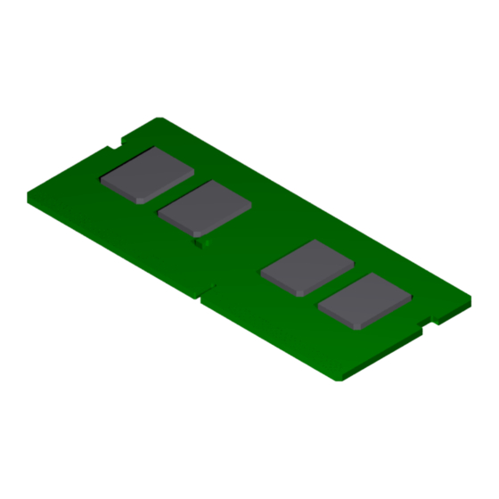
Memory Module This kit provides a memory module for NCR CX7 All-in-One POS (7772) or NCR CX8 POS (7736). 7772-K134 – 8GB Memory Module 7772-K136 – 16GB Memory Module Kit Contents Item Part Number Description 7772-K134 8GB Memory Module 006-8626889 Memory Module – 8GB, DDR4 2400MHz, SO-DIMM, 1.2V 7772-K136 16GB Memory Module... -
Page 6: Installation Procedure
Remove the two (2) screws that secure the Cable Cover to the Back Cover. b. Rotate and unhook the Cable Cover from the Back Cover. Confidential and proprietary information of NCR Corporation. Unauthorized use, reproduction and/or distribution is strictly prohibited. - Page 7 Remove the Ethernet Cable from the Cable Management Hook then disconnect the Cable. 4. Loosen the two (2) captive screws that secure the Back Cover to the Display. Confidential and proprietary information of NCR Corporation. Unauthorized use, reproduction and/or distribution is strictly prohibited.
- Page 8 5. Rotate the Back Cover away from the Display and unhook the Back Cover Tabs. Confidential and proprietary information of NCR Corporation. Unauthorized use, reproduction and/or distribution is strictly prohibited.
-
Page 9: Ncr Cx8 Pos
1. Remove the Top Cover. There are two types of Top Covers: Top Cover without Duct — Remove the four (4) screws securing the Top Cover to the chassis. Confidential and proprietary information of NCR Corporation. Unauthorized use, reproduction and/or distribution is strictly prohibited. - Page 10 Top Cover with Duct a. Remove the four (4) screws securing the Top Cover to the chassis. b. Slide the Top Cover in the direction shown. Confidential and proprietary information of NCR Corporation. Unauthorized use, reproduction and/or distribution is strictly prohibited.
- Page 11 3. Press the Memory Module down until it latches in position. Ensure the latches are completely engaged. 4. Reinstall the Top Cover. Top Cover without Duct – Install the Top Cover on the chassis using four (4) screws. Confidential and proprietary information of NCR Corporation. Unauthorized use, reproduction and/or distribution is strictly prohibited.
- Page 12 Slide the Top Cover in the direction shown to align the screw holes of the Cover with the screw holes of the chassis. c. Secure the Top Cover with four (4) screws. Confidential and proprietary information of NCR Corporation. Unauthorized use, reproduction and/or distribution is strictly prohibited.