
Related Manuals for Cub Cadet Zero-Turn Commercial Riding Mower Professional Turf Equipment


Summary of Contents for Cub Cadet Zero-Turn Commercial Riding Mower Professional Turf Equipment
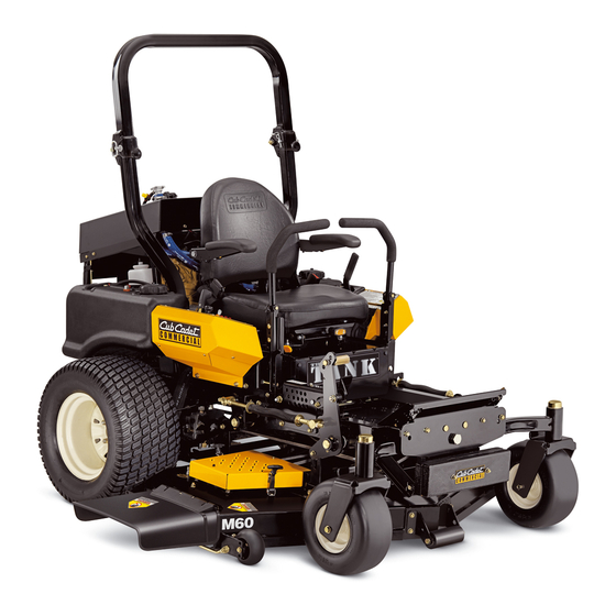
- Page 1 Hydrostatic Zero-Turn Commercial Riding Mower Professional Turf Equipment 60” & 72” Fabricated Deck InDirect Injection Diesel OPERATOR’S AND SERVICE MANUAL...
-
Page 2: Table Of Contents
TABLE OF CONTENTS Foreword............. . . 3 General Safety Operations . -
Page 3: Foreword
FORWARD The Tank Hydrostatic Zero-Turn Commercial Riding Mower provides superb maneuverability, mid-mount cutting capability for professional landscapers, commercial lawn service compa- nies, professional turf managers and golf course superintendents. The machine incorporates many safety features that should be studied by all operators and maintenance personnel before use. -
Page 4: General Safety Operations
GENERAL SAFETY OPERATIONS A. DANGER Do not operate machine in confined areas where exhaust gases can accumulate. Do not operate machine without mower chute deflector in place and operational. Do not carry passengers. B. WARNING 1. Do not operate machines under the influence of alcohol or drugs. -
Page 5: Related To Fuel
ture. Keep sparks and flames away at all times. 11. When looking for oil leaks, never run your hand over hydraulic hoses, lines or fittings. Never tighten or adjust hydraulic hoses, lines or fittings while the system is under pressure. If high-pressure oil penetrates the skin, the oil must be removed within a few hours by a doc- tor familiar with this form of injury or serious... -
Page 6: Towing
damage. Make sure the blades are in good condition and that the blade bolts are tight before restarting the engine. 13. Never leave the mower unattended without: turning off the blade clutch switch; placing the left and right steering levers in the neutral position;... -
Page 7: G.suspension Seat
over...use caution in (or avoid) areas where the ROPS could come in contact with any structures, trees, etc. 8. The ROPS and seat belt add additional mass that elevates the machine’s Center of Gravity (C.G.) which negatively affects the machine’s stability and traction...use extra caution when operating on slopes. -
Page 8: Safety Decals
SAFETY DECALS AND LABELS Part Number: 00030635 Part Number: 777S32798 Part Number: 777S32797 ! WARNING! Maximum weight on hitch is 50 lbs. Maximum towed load is 500 lbs. Never allow passengers on towed equipment. Loss of traction can occur on slopes, 5 (9%) maximum grade. Travel slowly and allow extra distance to stop. -
Page 9: Specifications
SPECIFICATIONS GENERAL INFO. Controls: Engine ignition and start switch; throttle; left and right steering levers; electric blade clutch switch; parking brake; mower deck lift Parking Brake: Mechanical linkage attached to the brake handle and drum brakes Seat: Fully adjustable Suspension Seat-fore/aft, seatback, armrests and operator weight adjustments Frame: 2"... -
Page 10: Operating Instructions
OPERATING INSTRUCTIONS Figure. 1 Hour Meter Glow Plug (tach optional) indicator lights Ignition Switch A.General 1. When Mowing: a. Keep adults, children, and pets away from the area to be mowed. b. When operating this mower, in the forward direction, do not allow the steering levers to return to Neutral on their own. -
Page 11: Controls
of grease, grass, and leaves to reduce the chance of fire and permit proper cooling. Note: If low traction conditions occur, follow these procedures for “zero turns”: To turn clockwise (front of machine moves toward RIGHT) when traveling FORWARD: 1. Come to a stop, 2. - Page 12 Steering Levers Figure. 3 Foot Pedal Lift the rear to the front will increase the engine speed from slow to fast. 4. Left and Right Steering Levers: (See Figure 3.) These hinged levers open out to the side in any position to permit the operator to be seated or to leave the mower’s seat.
-
Page 13: Initial Adjustments
Figure. 4 Fuel Shutoff Valve operation - thusly the hands can be used for other functions 8. Fuel Shutoff Valve: (See Figure 4.) Located behind the operator’s seat, the valve has three (3) positions: “off”, “Left Tank”, “Right Tank”. Close this valve if you are not going to run the mower for a period of 30 minutes or more to prevent flooding the engine. -
Page 14: Zero Turn Break-In And Operating Procedures
lower the mowing deck into the cutting posi- tion. b. Using a ruler, pencil and paper, measure and note the distance from the paved surface to the bottom edge of the mowing blade at the front and the back of the deck on each side of the mower. - Page 15 Riders are not permitted under any circum- stance! To start the engine on the machine: 1. Make sure the park brake is set to the “ON” position, both lap bars are in the neutral/ start position, and the Power Take Off (PTO also referred to as blade control switch) is in the “off”...
-
Page 16: Mower Cutting Blades
bar forward while simultaneously moving the RIGHT lap bar rearward. Release both lap bars and the machine should stop turning. 3. To turn counter-clockwise, slowly move the RIGHT lap bar forward while simultaneously moving the LEFT lap bar rearward. Release both lap bars and the machine should stop turning (this is a safety check, the normal procedure is for the operator to slowly bring... -
Page 17: Cooling System
Height of Cut Clevis Pin Figure. 6 required for these blades when compared to others, and they generally produce the highest noise levels. Medium-lift- These blades require less horsepower than the hi-lift, and they generally work well in wider leaf grasses and some mulch applications. -
Page 18: Hydraulic Oil
Cover Plate Spindle Figure. 7 side of the cutter deck (2); remove the linch- pins on the left and right front side of the cut- ter deck (2); and remove the linchpins on the front of the mower (2). Turn front caster wheels outward. g. -
Page 19: Electrical System
Figure. 8 Hydraulic Tank Adding Hydraulic Oil (use Shell Rimula 15W40) a. Place the Mower on a level surface and engage the parking brake. b. Stop the engine and remove the key from the ignition switch. Clean the area around the Hydraulic Oil fill neck. - Page 20 c. Store the battery with a full charge. A dis- charged battery will freeze (refer to the table below). Specific Gravity Freezing Temp (°F) 1.265 1.250 1.200 1.150 1.100 d. Recharge battery when ever the specific gravity value is less than 1.225 Battery Removal Warning: When removing the cables from the battery fol-...
-
Page 21: Tires
start. If it does, the parking brake switch must be repositioned or perhaps replaced. If the engine does not start, engage the parking brake and start the engine. c. Seat Switch: With both steering levers in the neutral position, the parking brake engaged and the blade clutch switch in the “off”... -
Page 22: Hydraulic System
mower is parked with the engine shut off, the hydraulic system locks the traction wheels. Note: To move the mower forward or in reverse by pushing, you must release the dynamic braking. Locate the valves on the pump. Turn valves counter-clockwise (using a standard 7/16”... - Page 23 Note: The pumps are not owner-repairable. If a pump fails, contact your Cub Cadet Com- mercial dealer. Do not disassemble the pump. 4. Steering Lever Adjustments: The steering lever controls on this Zero Turn Mower (ZTM)
-
Page 24: G.cooling System
G.Cooling System The cooling system should be inspected on a regular basis for restrictions to air flow through the heat exchanger core, and for leaks. The heat exchanger core should be cleaned by moderate (50 psi) pressure air or water, but not by brushing. -
Page 25: Maintenance Schedule
MAINTENANCE SCHEDULE A. Daily Checks 1. Before starting engine: a. Check the fuel level.** b. Check the fuel strainer water trap and drain off contaminants if present. c. Check the engine oil level.** d. Check the hydraulic oil level. e. Check the hydraulic hoses for leaks, abra- sion, kinks, twists, or a flattened condition. -
Page 26: Lubrication Chart
OIL CHART Apply a few drops of engine oil or use a spray lubricant. Apply the oil to both sides of pivot points. Wipe off any excess. Start engine and operate mower briefly to insure that oil spreads evenly. Number of Oil Points Description DAILY Deck Suspension Pivots... -
Page 27: Performance Adjustments
Performance Adjustments A. High Speed Tracking Adjustment If mower tracks to one side with both lap bars in fully forward position: Check air pressure in all four tires: a. Pressure should be within specified ranges and balanced side-to-side. b. Rear tires 10-12 psi. recommended (20 psi MAX.) c. -
Page 28: Deck Corner Ball Wheel Roller Settings
C. Deck Corner Ball Wheel Roller Settings Matching the set heights of the ball rollers on the four corners of the mower deck to the desired cut height will prevent edge scalping and minimize any side-to-side variance in cut height. There are three height adjustment holes in the bracket that mount the ball rollers to the deck. -
Page 29: F Deck Leveling Procedure
F. Deck leveling Procedure Park the mower on a flat paved surface, engage the parking brake, shut off the engine, remove the key from the ignition switch, disconnect the spark plug wires and using the second foot pedal, lower the mowing deck into the 4"... -
Page 30: Fuel And Lube Specifications
Fuel & Lube Specifications A.Fuel Specifications Use good quality fuel to get the correct power and per- formance from the engine. The recommended fuel spec- ification for Caterpillar engines is shown below. Cetane number 45 minimum Viscosity 2.0/4.5 centistrokes at 40 C (104 F) Density 0,835/0,855 kg/litre Sulphur... -
Page 31: Wiring Diagram
WIRING DIAGRAM GD: 02003026... - Page 32 Notes...
- Page 33 Notes...
- Page 34 Notes...
- Page 36 The limited warranty set forth below is given by Cub Cadet LLC with respect to new merchandise used for commercial and related purposes...