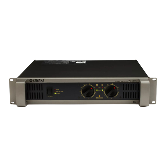
Yamaha P2500S Owner's Manual
Yamaha p2500s: owners manual
Hide thumbs
Also See for P2500S:
- Manuel d'instructions (16 pages) ,
- Service manual (73 pages) ,
- Owner's manual (16 pages)
Table of Contents
Advertisement
Advertisement
Table of Contents

Summary of Contents for Yamaha P2500S
- Page 1 POWER AMPLIFIER Owner’s Manual...
-
Page 2: Explanation Of Graphical Symbols
The wire which is coloured BROWN must be connected to the termi- nal which is marked with the letter L or coloured RED. • This applies only to products distributed by Yamaha-Kemble Music (U.K.) Ltd. • Explanation of Graphical Symbols The lightning flash with arrowhead symbol... - Page 3 Installation Connect this unit’s power cord only to an AC outlet of the type stated in this Owner’s Manual or as marked on the unit. Failure to do so is a fire and electrical shock hazard. Do not allow water to enter this unit or allow the unit to become wet.
- Page 4 1. IMPORTANT NOTICE: DO NOT MODIFY THIS UNIT! This product, when installed as indicated in the instructions contained in this manual, meets FCC requirements. Modifications not expressly approved by Yamaha may void your authority, granted by the FCC, to use the product. 2. IMPORTANT: When connecting this product to accessories and/or another product use only high quality shielded cables.
-
Page 5: Table Of Contents
Introduction Thank you for your purchase of the YAMAHA P7000S, P5000S, P3500S or P2500S power amplifier. These P-series amplifiers fully incorporate Yamaha’s renown technological expertise, and offer high reliability, rock-solid stability, and superb acoustic characteristics—all in a trim, 2U-sized package. -
Page 6: Controls And Functions
DC voltage is detected at the amplifier outputs. Also lights up for about three seconds at time of power-on, as the amp gets ready to operate. To provide protection, the unit will not output any sound from the speakers while this indicator is lit up. -
Page 7: Rear Panel
FILTER switch is set to OFF. NOTE: This feature provides improved frequency reponse on speakers such as the YAMAHA S112 and S115. 3 INPUT jacks (Channels A, B) Two jack types are provided for each channel. Note that if you are using BRIDGE or PARALLEL mode, only the Channel A jacks are effective. - Page 8 4 STEREO/PARALLEL/BRIDGE switch Use this switch to select the operating mode. • STEREO mode Channels A and B operate independently (as with a conven- tional stereo amplifier). The Channel A input goes to the Chan- nel A output jacks, and the Channel B input goes to the Channel B output jacks.
-
Page 9: Speaker Connections
Speaker Connections I Speaker impedance Speakers can be connected to the amplifier as shown below. Note that speaker impedance will vary according to the connection method and the number of speakers. Please be sure that your speakers Connection configurations for STEREO and PARALLEL modes When using 5-way binding post output jacks STEREO BRIDGE PARALLEL... -
Page 10: Wiring
Note to users in the USA: Please use Class 3 wiring. (P7000S, P5000S) Please use Class 2 wiring. (P3500S, P2500S) Be sure that the bare wire ends do not jut out from the ter- minals and touch the chassis. The following shows how the cable should look when correctly attached. -
Page 11: Rack Mounting
Mounting in a standard EIA rack If you are mounting multiple power amplifiers in a rack, be sure to install ventilation panel(s) as shown below. Also be sure to use metal brack- ets (one on each side) to support the rear of each amplifer. Note: EIA stands for Electronic Industries Alliance. -
Page 12: Specifications
Specifications and descriptions in this owner’s manual are for information purposes only. Yamaha Corp. reserves the right to change or modify products or spec- ifications at any time without prior notice. Since specifications, equipment or options may not be the same in every locale, please check with your Yamaha dealer. -
Page 13: Block Diagram
I Block Diagram P7000S, P5000S P3500S, P2500S State variable Active filter CHANNEL A [BRIDGE] [PARALLEL] INPUT CHANNEL B State variable Active filter POWER POWER SW CHANNEL A Limiter Frequency [25 Hz-150 Hz] YAMAHA SPEAKER PROCESSING YAMAHA SPEAKER PROCESSING CHANNEL B... -
Page 14: Dimensions
Output Power [W] P3500S 10000 1000 Output Power [W] P5000S Mode:STEREO Both ch Driven RL=4 Ω, f=1 kHz 1000 10000 P2500S Mode:STEREO Both ch Driven RL=4 Ω, f=1 kHz 1000 Unit: mm Mode:STEREO Both ch Driven RL=4 Ω, f=1 kHz 10000 1000... -
Page 15: Troubleshooting
Possible Cause A DC voltage of ±2 V or greater Consult your dealer or the was generated in the power nearest Yamaha service center. amplifier’s output circuit. Possible Cause A DC voltage of ± 2 V or greater Consult your dealer or the was generated in the power nearest Yamaha service center. -
Page 16: North America
For details of products, please contact your nearest Yamaha representative or the authorized distributor listed below. Pour plus de détails sur les produits, veuillez-vous adresser à Yamaha ou au distributeur le plus proche de vous figurant dans la liste suivante.


