Advertisement
Quick Links
Advertisement

Related Manuals for NCR 7358-K582


Summary of Contents for NCR 7358-K582
- Page 1 Kit Instructions Bottom-of-Basket Camera 7358-K582 Issue B...
- Page 2 NCR, therefore, reserves the right to change specifications without prior notice. All features, functions, and operations described herein may not be marketed by NCR in all parts of the world. In some instances, photographs are of equipment prototypes. Therefore, before using this document, consult with your NCR representative or NCR office for information that is applicable and current.
-
Page 3: Revision Record
Revision Record Issue Date Remarks First issue. 2019 Added 2019 Changing Bottom-of- Basket Camera Orientation page 9. - Page 4 This publication provides procedures for installing the BoB Camera on a Large Basket Module. The NCR FastLane SelfServ™ Checkout (7358) R6L Plus with a Bagging Area (Bagwell) Module or Large Basket (Basket) Module can be configured for either Left-hand (LH) orientation or Right-hand (RH) orientation, which refers to the direction customers scan and bag items.
-
Page 5: Kit Contents
7358-K582 Bottom-of-Basket Camera Kit Contents Part Numbers Description 497-0524617 7358-K582 KIT - BOTTOM OF BASKET CAMERA * 497-0525400 Assembly - USB 2.0 High Speed Camera with 6m USB cable 497-0523191 Clear Lens Shield 497-0524539 Camera Bracket Assembly • Serrated Nut-Self Locking (Hex, M4, 4.2) (2 pcs) •... -
Page 6: Installation Procedure
7358-K582 Bottom-of-Basket Camera Installation Procedure To install the Bottom-of-Basket Camera, follow these steps: Note: For the purpose of illustration only, this procedure shows images using Left- hand (LH) orientation. 1. Access the camera mounting hole and cable access holes by doing the following: a. - Page 7 7358-K582 Bottom-of-Basket Camera 2. Remove two (2) nuts to detach the camera blanking plate from the Bagwell wall, as shown in the image below. 3. Do the following: a. Attach the Lens Shield to the Camera.
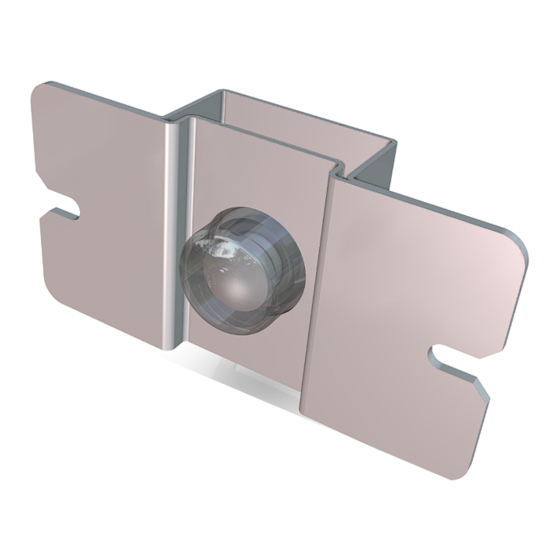
- Page 8 7358-K582 Bottom-of-Basket Camera b. Insert the Camera into the Lens Shield Spacer hole, as shown in the image below. c. Position the Camera Bracket so that its screw slots are aligned with the screw slots of the Lens Shield Spacer.
- Page 9 7358-K582 Bottom-of-Basket Camera 5. Secure the Camera USB cable on the camera bracket using a cable tie. 6. Position the Camera assembly on the Camera mounting hole and then secure using two (2) nuts.
- Page 10 7358-K582 Bottom-of-Basket Camera 7. Route the cable to the SelfServ Checkout unit through the cable access holes of the Bagwells. 8. Depending on the SelfServ Checkout unit, connect the other end of the cable to the corresponding ports, as shown in the table below.
- Page 11 7358-K582 Bottom-of-Basket Camera 9. Do the following: a. Install the top cover trays to close the Bagwells. b. Push and turn the Service screws counterclockwise at approximately ⅟₄ turn to lock the top cover trays in place, as shown in the image below.
- Page 12 7358-K582 Bottom-of-Basket Camera Changing Bottom-of-Basket Camera Orientation To change the orientation of the Bottom-of-Basket Camera, follow these steps: Note: This procedure should be done only when changing the orientation of the Large Basket Angled Module (V-Bagwell). For the purpose of illustration only, this procedure shows images converting a Left-hand (LH) orientation to a Right-hand (RH) orientation.
- Page 13 7358-K582 Bottom-of-Basket Camera • Remove two (2) nuts to detach the Camera assembly from the Camera mounting hole.
- Page 14 7358-K582 Bottom-of-Basket Camera 3. Install the Camera assembly and blanking plate inside the Bagwell by doing the following: • Secure the Camera assembly to the Camera mounting hole on the other side of the V-Bagwell using two (2) nuts, as shown in the image below.
- Page 15 7358-K582 Bottom-of-Basket Camera 4. Route the cable to the SelfServ Checkout unit through the cable access holes of the Bagwells, as shown in the image below. 5. Depending on the SelfServ Checkout unit, connect the other end of the cable to the corresponding ports.