
Related Manuals for Miller XMT 350 VS Auto-Line


Summary of Contents for Miller XMT 350 VS Auto-Line
- Page 1 OM-225 604E 2006−10 Processes Multiprocess Welding Description Arc Welding Power Source ™ XMT 350 VS Auto-Line ™ (With Voltage Reduction Device) File: MULTIPROCESS Visit our website at www.MillerWelds.com...
- Page 2 We know you don’t have time to do it any other way. That’s why when Niels Miller first started building arc welders in 1929, he made sure his products offered long-lasting value and superior quality.
-
Page 3: Table Of Contents
TABLE OF CONTENTS SECTION 1 − SAFETY PRECAUTIONS - READ BEFORE USING ........1-1. -
Page 5: Section 1 − Safety Precautions - Read Before Using
SECTION 1 − SAFETY PRECAUTIONS - READ BEFORE USING som _3/05 Y Warning: Protect yourself and others from injury — read and follow these precautions. 1-1. Symbol Usage Means Warning! Watch Out! There are possible hazards with this procedure! The possible hazards are shown in the adjoining symbols. - Page 6 ARC RAYS can burn eyes and skin. BUILDUP OF GAS can injure or kill. D Shut off shielding gas supply when not in use. Arc rays from the welding process produce intense visible and invisible (ultraviolet and infrared) rays D Always ventilate confined spaces or use that can burn eyes and skin.
-
Page 7: Additional Symbols For Installation, Operation, And Maintenance
D Read Owner’s Manual before using or servic- support unit. ing unit. D If using lift forks to move unit, be sure forks are D Use only genuine Miller/Hobart replacement long enough to extend beyond opposite side of parts. unit. -
Page 8: Principal Safety Standards
1-5. Principal Safety Standards Safety in Welding, Cutting, and Allied Processes, ANSI Standard Z49.1, Boulevard, Rexdale, Ontario, Canada (phone: from Global Engineering Documents (phone: 1-877-413-5184, website: 800−463−6727 or in Toronto 416−747−4044, website: www.csa−in- www.global.ihs.com). ternational.org). Practice For Occupational And Educational Eye And Face Protection, Recommended Safe Practices for the Preparation for Welding and Cut- ANSI Standard Z87.1, from American National Standards Institute, 11 ting of Containers and Piping, American Welding Society Standard... -
Page 9: Section 2 − Consignes De Sécurité − Lire Avant Utilisation
SECTION 2 − CONSIGNES DE SÉCURITÉ − LIRE AVANT UTILISATION som _3/05 Y Avertissement : se protéger et protéger les autres contre le risque de blessure — lire et respecter ces consignes. 2-1. Symboles utilisés Symbole graphique d’avertissement ! Attention ! Cette pro- cédure comporte des risques possibles ! Les dangers éven- tuels sont représentés par les symboles graphiques joints. - Page 10 LES RAYONS D’ARC peuvent entraî- ACCUMULATIONS ner des brûlures aux yeux et à la peau. risquent de provoquer des blessures ou même la mort. Le rayonnement de l’arc du procédé de soudage génère des rayons visibles et invisibles intenses D Fermer l’alimentation du gaz protecteur en cas (ultraviolets et infrarouges) susceptibles de provo- de non-utilisation.
-
Page 11: Dangers Supplémentaires En Relation Avec L'installation, Le Fonctionnement Et La Maintenance
D Utiliser un équipement de levage de capacité D Utiliser uniquement des pièces de rechange suffisante pour lever l’appareil. Miller/Hobart. D En utilisant des fourches de levage pour déplacer l’unité, s’assu- rer que les fourches sont suffisamment longues pour dépasser du côté... -
Page 12: Principales Normes De Sécurité
2-5. Principales normes de sécurité Safety in Welding, Cutting, and Allied Processes, ANSI Standard Z49.1, Boulevard, Rexdale, Ontario, Canada M9W 1R3 (téléphone : de Global Engineering Documents (téléphone : 1-877-413-5184, site In- 800-463-6727 ou à Toronto 416-747-4044, site Internet ternet : www.global.ihs.com). www.csa-international.org). -
Page 13: Section 3 − Introduction
SECTION 3 − INTRODUCTION 3-1. Specifications RMS Amps Input at Rated Load Output, Max. 60 Hz 3-Phase at NEMA Load Voltages Amperage Open- and Class I Rating Input Input Voltage Voltage Range in Range in Circuit Circuit Power Range in CV Mode 208 V 230 V 400 V... -
Page 14: Duty Cycle And Overheating
3-3. Duty Cycle And Overheating Duty Cycle is percentage of 10 min- utes that unit can weld at rated load without overheating. If unit overheats, output stops, a Help message is displayed and cooling fan runs. Wait fifteen min- utes for unit to cool. Reduce amper- age or voltage, or duty cycle before welding. -
Page 15: Section 4 − Installation
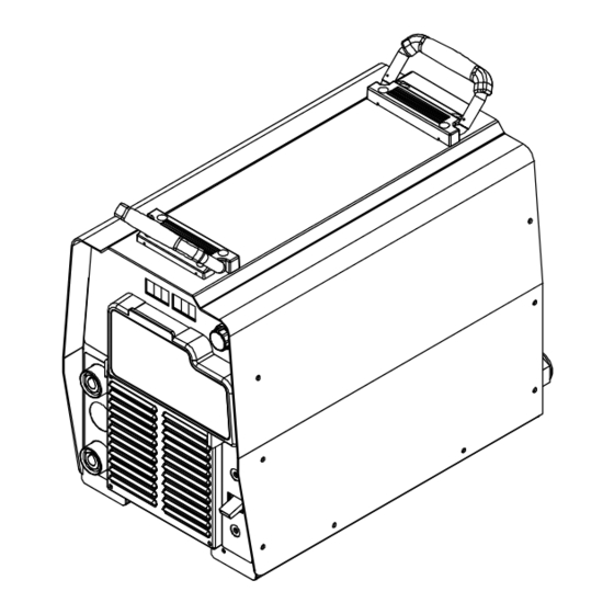
SECTION 4 − INSTALLATION 4-1. Selecting a Location 24 in (610 mm) Dimensions And Weight 80 lb (36.3 kg) 17 in (432 mm) 12-1/2 in (318 mm) Lifting Handles Movement Use handles to lift unit. Hand Cart Y Do not move or operate unit Use cart or similar device to move where it could tip. -
Page 16: Connecting 1-Phase Input Power
4-2. Connecting 1-Phase Input Power Y Installation must meet all Na- tional and Local Codes − have only qualified persons make this installation. Y Disconnect and lockout/tag- out input power before con- necting input conductors from unit. Y Always connect green or green/yellow conductor supply grounding terminal =GND/PE... -
Page 17: Connecting 3-Phase Input Power
4-3. Connecting 3-Phase Input Power Y Installation must meet all National and Local Codes − have only quali- fied persons make this installation. Y Disconnect and lockout/tagout in- put power before connecting input conductors from unit. Y Always connect green or green/ yellow conductor supply... -
Page 18: Electrical Service Guide
4-4. Electrical Service Guide CAUTION: INCORRECT INPUT POWER can damage this welding power source. Phase to ground voltage shall not exceed +10% of rated input voltage. NOTE Actual input voltage should not be 10% less than minimum and/or 10% more than maximum input voltages listed in table. -
Page 19: Weld Output Terminals And Selecting Cable Sizes
4-5. Weld Output Terminals And Selecting Cable Sizes Y ARC WELDING can cause Electromagnetic Interference. To reduce possible interference, keep weld cables as short as possible, close together, and down low, such as on the floor. Locate welding operation 100 meters from any sensitive electronic equipment. Be sure this welding machine is installed and grounded according to this manual. -
Page 20: Optional Gas Valve Operation And Shielding Gas Connection
‘ 4-6. Optional Gas Valve Operation And Shielding Gas Connection Obtain gas cylinder and chain to running gear, wall, or other station- ary support so cylinder cannot fall and break off valve. Cylinder Regulator/Flowmeter Install so face is vertical. Gas Hose Connection GAS IN Fitting has 5/8-18... -
Page 21: Section 5 − Operation
SECTION 5 − OPERATION 5-1. Front Panel Controls Power Switch For Air Carbon Arc (CAC-A) cutting and goug- assist with arc starts as well as reduce stick- ing, place switch in Stick position. For best re- ing while welding. The fan motor is thermostatically sults, place Arc Control in the maximum posi- controlled and only runs when cooling is tion. -
Page 22: Meter Functions
5-2. Meter Functions NOTE The meters display the actual weld output values for approximately three seconds after the arc is broken. Mode Meter Reading At Idle Meter Reading While Welding Scratch 24.5 13.4 Start TIG Actual Volts (OCV) Preset Amps Actual Volts Actual Amps 14.1... -
Page 23: Lift-Arc Tig Procedure
5-4. Lift-Arc TIG Procedure With Process Switch in the Lift-Arc TIG position, start an arc as follows: TIG Electrode Workpiece Touch tungsten electrode to work- piece at weld start point, hold electrode to workpiece for 1-2 seconds, and slowly lift electrode. An arc will form when electrode is lifted. -
Page 24: Section 6 − Maintenance & Troubleshooting
SECTION 6 − MAINTENANCE & TROUBLESHOOTING 6-1. Routine Maintenance Y Disconnect power Maintain more often before maintaining. during severe conditions. 3 Months Repair Or Replace Replace Cracked Replace Damaged Or Torch Body Cracked Unreadable Cables Labels Repair Or Replace Cracked Cables And Cords Clean Tighten Weld... -
Page 25: Voltmeter/Ammeter Help Displays
6-3. Voltmeter/Ammeter Help Displays HE.L P−1 HE.L P−5 HE.L P−2 HE.L P−6 HE.L P−3 HE.L P−8 PrO CES heated. The unit has shut down to allow the by the input current. When this limit is All directions are in reference to the front fan to cool it (see Section 3-3). -
Page 26: Section 7 − Electrical Diagram
SECTION 7 − ELECTRICAL DIAGRAM Figure 7-1. Circuit Diagram OM-225 604 Page 22... - Page 27 225 602-B OM-225 604 Page 23...
-
Page 28: Section 8 − Parts List
SECTION 8 − PARTS LIST Ref. 804 261-D Figure 8.1. Parts Assembly OM-225 604 Page 24... - Page 29 Item Dia. Part Mkgs. Description Quantity Figure 8.1. Parts Assembly ....216 034 Wrapper (Includes Insulators and Safety Labels) ....
- Page 30 Item Dia. Part Mkgs. Description Quantity Figure 8.1. Parts Assembly (Continued) ....126 026 ..Label, Warning Electric Shock Can Kill Significant .
- Page 31 Effective January 1, 2006 (Equipment with a serial number preface of “LG” or newer) This limited warranty supersedes all previous Miller warranties and is exclusive with no other Warranty Questions? guarantees or warranties expressed or implied. LIMITED WARRANTY − Subject to the terms and conditions...
-
Page 32: Options And Accessories
Contact the Delivering Carrier to: File a claim for loss or damage during shipment. For assistance in filing or settling claims, contact your distributor and/or equipment manufacturer’s Transportation Department. © PRINTED IN USA 2006 Miller Electric Mfg. Co. 2006−01...