Table of Contents
Advertisement
Quick Links
Advertisement
Table of Contents
Troubleshooting

Related Manuals for Miller XMT 350 FieldPro


Summary of Contents for Miller XMT 350 FieldPro
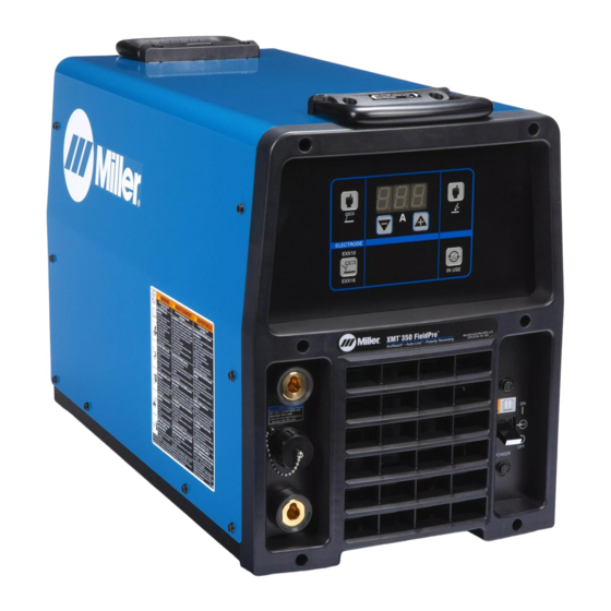
- Page 1 OM-282217J 2022−03 Processes Multiprocess Welding Description Arc Welding Power Source XMT 350 FieldPro ™ With Auto-Line, ArcReach ™ And Polarity Reversing For product information, File: Multiprocess Owner’s Manual translations, and more, visit www.MillerWelds.com...
- Page 2 We know you don’t have time to do it any other way. That’s why when Niels Miller first started building arc welders in 1929, he made sure his products offered long-lasting value and superior quality.
-
Page 3: Table Of Contents
TABLE OF CONTENTS SECTION 1 − SAFETY PRECAUTIONS - READ BEFORE USING ....... . . 1-1. - Page 4 TABLE OF CONTENTS SECTION 6 − OPERATION ..............6-1.
- Page 5 DECLARATION OF CONFORMITY for European Community (CE marked) products. MILLER Electric Mfg. LLC, 1635 Spencer Street, Appleton, WI 54914 U.S.A. declares that the product(s) identified in this declaration conform to the essential requirements and provisions of the stated Council Directive(s), Commission Regulation(s) and Standard(s).
- Page 6 DECLARATION OF CONFORMITY for United Kingdom (UKCA marked) products. MILLER Electric Mfg. LLC, 1635 Spencer Street, Appleton, WI 54914 U.S.A. declares that the product(s) identified in this declaration conform to the essential requirements and provisions of the stated Regulation(s) and Standard(s).
- Page 7 INVISION 352 MPA 230-460 AUTO-LINE W/AUX PWR, & (CE) 907431002 ALUMAPOWER 350 MPA 230-460 AUTO-LINE W/AUX PWR, (CE) 907420003 XMT 350 FIELDPRO 230-460V, (CE), DINSE 907730001 XMT 350 FIELDPRO 230-460V, POLARITY REVERSING, CE, 907731001 DINSE Compliance Information Summary Applicable regulation Directive 2014/35/EU...
-
Page 9: Section 1 − Safety Precautions - Read Before Using
SECTION 1 − SAFETY PRECAUTIONS - READ BEFORE USING som 2022−01 Protect yourself and others from injury — read, follow, and save these important safety precautions and operating instructions. 1-1. Symbol Usage DANGER! − Indicates a hazardous situation which, if Indicates special instructions. - Page 10 D Be aware that welding on a ceiling, floor, bulkhead, or partition can FUMES AND GASES can be hazardous. cause fire on the hidden side. D Do not cut or weld on tire rims or wheels. Tires can explode if heat- ed.
-
Page 11: Additional Hazards For Installation, Operation, And Maintenance
D Never weld on a pressurized cylinder − explosion will result. CYLINDERS can explode if damaged. D Use only correct compressed gas cylinders, regulators, hoses, and fittings designed for the specific application; maintain them Compressed gas cylinders contain gas under high and associated parts in good condition. -
Page 12: California Proposition 65 Warnings
H.F. RADIATION can cause interference. ARC WELDING can cause interference. D High-frequency (H.F.) can interfere with radio D Electromagnetic energy can interfere with navigation, safety services, computers, and sensitive electronic equipment such as communications equipment. computers and computer-driven equipment such as robots. D Have only qualified persons familiar with electronic equipment D Be sure all equipment in the welding area is electromagnetically perform this installation. -
Page 13: Section 2 − Consignes De Sécurité − Lire Avant Utilisation
SECTION 2 − CONSIGNES DE SÉCURITÉ − LIRE AVANT UTILISATION som_2022−01_fre Pour écarter les risques de blessure pour vous−même et pour autrui — lire, appliquer et ranger en lieu sûr ces consignes relatives aux précautions de sécurité et au mode opératoire. 2-1. - Page 14 D Ne pas toucher aux pièces chaudes, utiliser les outils recomman- D Se protéger et d’autres personnes de la projection d’étincelles et dés et porter des gants de soudage et des vêtements épais pour de métal chaud. éviter les brûlures. D Des étincelles et des matériaux chauds du soudage peuvent facilement passer dans d’autres zones en traversant de petites LES FUMÉES ET LES GAZ peuvent...
-
Page 15: Dangers Supplémentaires En Relation Avec L'installation, Le Fonctionnement Et La Maintenance
D Protéger les bouteilles de gaz comprimé d’une chaleur excessive, Les CHAMPS ÉLECTROMAGNÉTIQUES (CEM) des chocs mécaniques, des dommages physiques, du laitier, des peuvent affecter les implants médicaux. flammes ouvertes, des étincelles et des arcs. D Placer les bouteilles debout en les fixant dans un support station- D Les porteurs de stimulateurs cardiaques et naire ou dans un porte-bouteilles pour les empêcher de tomber ou autres implants médicaux doivent rester à... -
Page 16: Proposition Californienne 65 Avertissements
D Effectuer régulièrement le contrôle et l’entretien de l’installation. LIRE LES INSTRUCTIONS. D Maintenir soigneusement fermés les portes et les panneaux des sources de haute fréquence, maintenir les éclateurs à une distan- D Lire et appliquer les instructions sur les ce correcte et utiliser une terre et un blindage pour réduire les étiquettes et le Mode d’emploi avant l’instal- interférences éventuelles. -
Page 17: Section 3 − Definitions
SECTION 3 − DEFINITIONS 3-1. Additional Safety Symbols And Definitions Some symbols are found only on CE products. Warning! Watch Out! There are possible hazards as shown by the symbols. Safe1 2012−05 Do not discard product (where applicable) with general waste. Reuse or recycle Waste Electrical and Electronic Equipment (WEEE) by disposing at a designated collection facility. - Page 18 Welding sparks can cause fires. Have a fire extinguisher nearby, and have a watchperson ready to use it. Safe14 2012−05 Do not weld on drums or any closed containers. Safe16 2017−04 Do not remove or paint over (cover) the label. Safe20 2017−04 Flying pieces of parts can cause injury.
-
Page 19: Miscellaneous Symbols And Definitions
3-2. Miscellaneous Symbols And Definitions Amperage Three Phase Percent Negative Voltage Output Single Phase Variable Positive Inductance Gas Metal Arc Arc Force Remote Welding (GMAW) (DIG) Flux Cored Arc Flux Cored Arc Input Voltage Welding - Self Welding (FCAW) Shielded (FCAW-S) Shielded Metal Line Connection... -
Page 20: Section 4 − Specifications
4-4. Information About Default Weld Parameters And Settings NOTICE − Each welding application is unique. Although certain Miller Electric products are designed to determine and default to certain typical welding parameters and settings based upon specific and relatively limited application variables input by the end user, such default settings are for reference purposes only;... -
Page 21: Duty Cycle And Overheating
4-6. Duty Cycle And Overheating Duty Cycle is percentage of 10 minutes that unit can weld at rated load without overheating. If unit overheats, output stops, a Help message is dis- played and cooling fan runs. Wait fifteen minutes for unit to cool. -
Page 22: Dimensions And Weight
4-7. Dimensions And Weight Hole Layout Dimensions 12-7/8 in. (327 mm) 24 in. (610 mm) 4-11/16 in. (119 mm) 17 in. (432 mm) 15-3/4 in. (400 mm) 22-3/32 in. (561 mm) 12-1/2 in. (318 mm) 8-11/16 in. (221 mm) 1-17/32 in. (39 mm) 278579-A 279972-B 1-11/16 in. - Page 23 Model Input Minimum Power Source Efficiency Maximum Idle State Power Consumption XMT 350 FieldPro 400V Three Phase 85.4 % 30.5 W Do not discard product (where applicable) with general waste. Reuse or recycle Waste Electrical and Electronic Equipment (WEEE) by disposing at a designated collection facility.
-
Page 24: Section 5 − Installation
SECTION 5 − INSTALLATION 5-1. Selecting A Location Movement Do not move or operate unit where it could tip. Location And Airflow Special installation may be required where gasoline or volatile liquids are present − see NEC Article 511 or CEC Section 20. -
Page 25: Remote 14 Receptacle Information
5-2. Remote 14 Receptacle Information Socket* Socket Information C L N 14 volts DC. Circuit limited to 35 mA. 14 VOLTS DC Contact closure to A completes contactor control circuit. Output to remote control; +10 volts DC. Remote control circuit common. REMOTE OUTPUT CONTROL... -
Page 26: Connecting 3-Phase Input Power
5-4. Connecting 3-Phase Input Power = GND/PE Earth Ground Tools Needed: input2 2012−05 − 803766-C / Ref. 279972-B OM-282217 Page 18... - Page 27 5-4. Connecting 3-Phase Input Power (Continued) voltage available at site. This unit can be con- Input Conductors (L1, L2 And L3) Installation must meet all National and nected to any input power between 208 and Local Codes − have only qualified per- Disconnect Device Line Terminals 575 VAC without removing cover to relink the sons make this installation.
-
Page 28: Weld Output Receptacles And Selecting Cable Sizes
5-5. Weld Output Receptacles And Selecting Cable Sizes* NOTICE − The Total Cable Length in Weld Circuit (see table below) is the combined length of both weld cables. For example, if the power source is 100 ft (30 m) from the workpiece, the total cable length in the weld circuit is 200 ft (2 cables x 100 ft). Use the 200 ft (60 m) column to determine cable size. -
Page 29: Stick Connections
5-7. Stick Connections Work Output Terminal Connect work lead to work output terminal. Electrode Output Terminal Connect electrode holder to electrode output terminal. 279989-B Notes OM-282217 Page 21... -
Page 30: Tig Lift-Arct Connections
5-8. TIG Lift-Arct Connections NOTICE − HF Arc Starters will damage this unit. Do not use high frequency devices with this unit. Work Output Terminal Connect work lead to work output terminal. Electrode Output Terminal Connect TIG torch with gas valve to electrode output terminal. -
Page 31: Connecting Voltage Sensing Suitcase Feeder
5-9. Connecting Voltage Sensing SuitCase Feeder Turn Off wire feeder and welding power source. Stop engine on welding generator. Welding Power Source Gas Hose Weld Cable To Feeder Work Cable To Workpiece Weld cable and work cable connec- tions to power source (DCEN/ DCEP) are dependant on wire type. -
Page 32: Connecting To Remote
5-10. Connecting To Remote This power source can be used with either FieldPro Remote, RHC−14 remote, wireless remote (see RHC−14 remote or wireless remote Owner’s Manual for operating instructions). Power Source TIG Torch (Shielding Gas Not RHC-14 Or Wireless Remote Connection Shown) Electrode Holder When using an RHC-14 or wireless... - Page 33 Notes OM-282217 Page 25...
-
Page 34: Volt Sense Lead And Work Cable Connections For Multiple Welding Arcs
5-11. Volt Sense Lead And Work Cable Connections For Multiple Welding Arcs A. Ideal Setup 279991-B Welding Power Source Work Sense Lead Remote Workpiece Weld Cable The work sense lead is required for This arrangement is an ideal setup for Work Cable operation of the FieldPro Remote. - Page 35 B. Bad Setup 279997-B Welding Power Source Work Sense Lead This arrangement is a bad setup. Clamps for separate units should not be shared. Weld Cable Remote Weld cables should not be crossed. Work Cable Workpiece OM-282217 Page 27...
-
Page 36: Section 6 − Operation
SECTION 6 − OPERATION 6-1. Interface Controls 279973-A / 279936-A / Ref. 253664-A Power Switch Stick Electrode Type Select Button IN USE Button Amperage Adjustment Buttons AMPS Display 10 IN USE Indicator 14-Pin Remote Connected Indicator TIG Process Select Button 11 Check Polarity Indicator FieldPro Accessory Connected Stick Process Select Button... -
Page 37: Interface Operation Description
6-2. Interface Operation Description Power Switch Use this switch to power up or power down the welding power source. The fan is thermostatically controlled and only runs when cooling is needed. AMPS Display This display illuminates and shows amperage for either TIG or stick welding process. Measured amperage just prior to the end of a welding operation will appear on the display for ten seconds after welding operation. -
Page 38: Associating Arcreach Device To Arcreach Power Source
6-3. Associating ArcReach Device To ArcReach Power Source Quick Setup Guide: Make connections between power source and ArcReach device. (See section pertaining to mode being used for typical connection diagrams). This power source has the ability to associate with an ArcReach device at power up, or when an ArcReach wire feeder is triggered. See instructions in the owner’s manual for the specific ArcReach device to associate the device to this power source. -
Page 39: Lift-Arc Tig Procedure
6-7. Lift-Arc TIG Procedure With Process Switch in the TIG position, start an arc as follows: TIG Electrode Workpiece Touch tungsten electrode to work- piece at weld start point. Arc will not start while electrode is touching the workpiece. Slowly lift electrode to form an arc. -
Page 40: Carbon Arc Gouging
6-9. Carbon Arc Gouging Direction Of Travel 258443-A Electrode Holder Keep the arc short. valve. Use proper arc and travel speed to create the desired shape and condition of Choose correct electrode holder for the Workpiece the gouge. process. Start air compressor and adjust regulator Air Stream Always cut away from the operator as to correct setting. -
Page 41: Section 7 − Maintenance & Troubleshooting
SECTION 7 − MAINTENANCE & TROUBLESHOOTING 7-1. Routine Maintenance Disconnect power Maintain more often before maintaining. during severe conditions. 3 Months Repair Or Replace Replace Cracked Replace Damaged Or Torch Body Cracked Unreadable Cables Labels Repair Or Replace Cracked Cables And Cords Clean Tighten Weld... -
Page 42: Help Displays
7-3. Help Displays All directions are in reference to the front of the unit. All circuitry referred to is lo- cated inside the unit. Help 1, 6, 7 Display Indicates a malfunction in the primary power circuit. If this display is shown, contact a Fac- tory Authorized Service Agent. -
Page 43: Troubleshooting Welding Power Source
7-4. Troubleshooting Welding Power Source Trouble Remedy No weld output; unit completely in−operative Place line disconnect switch in On position (see Section 5-4). Check and replace line fuse(s), if necessary*. Check for proper input power connections (see Section 5-4). No weld output; meter display On. Check, repair, or replace RHC-14 remote control. -
Page 44: Section 8 − Electrical Diagram
SECTION 8 − ELECTRICAL DIAGRAM Figure 8-1. Welding Power Source Circuit Diagram OM-282217 Page 36... - Page 45 282214-C OM-282217 Page 37...
- Page 46 Notes...
- Page 47 Effective January 1, 2022 (Equipment with a serial number preface of NC or newer) This limited warranty supersedes all previous Miller warranties and is exclusive with no other guarantees or warranties expressed or implied. LIMITED WARRANTY − Subject to the terms and conditions Supplied Air Respirator (SAR) Boxes and Panels below, Miller Electric Mfg.
- Page 48 Contact the Delivering Carrier to: File a claim for loss or damage during shipment. For assistance in filing or settling claims, contact your distributor and/or equipment manufacturer’s Transportation Department. © ORIGINAL INSTRUCTIONS − PRINTED IN USA 2022 Miller Electric Mfg. LLC 2022−01...