
Related Manuals for QSFPTEK S5300-8TE4X-P


Summary of Contents for QSFPTEK S5300-8TE4X-P
- Page 1 S5300-8TE4X-P Quick Start Guide V2.0 8-Port Ethernet L2 Multi-Gigabit PoE Switch 8x 100/1000M/2.5GBASE-T PoE++ Ports, with 4x 10G SFP+ Uplinks, Support Stacking www.qsfptek.com V2.0 1 / 10...
- Page 2 The 2.5G switch offers 2.5GBASE-T interfaces to ensure a more stable and reliable network architecture for enterprises. We appreciate your decision to select S5300-8TE4X-P. This manual is intended to help you become acquainted with the switch design and provide instructions for implementing the switches into your network.
-
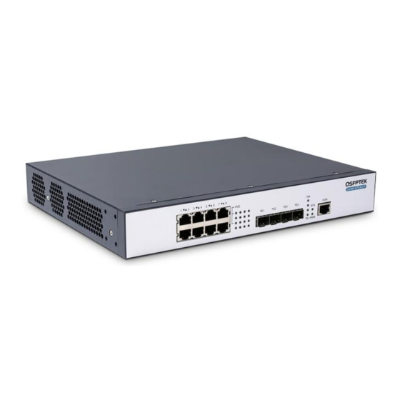
Page 3: Hardware Overview
SFP+ Green (Port TE1-TE4) 10G packets receiving or Blinking transmitting. If the SYS indicator flickers, SYS LED the system works normally. If the PWR indicator is PWR LED always on, the device is powered on. www.qsfptek.com V2.0 3 / 10... -
Page 4: Installation Requirements
Avoid incorrect operations that may cause damage to humans or devices. Site Environment Make sure that the workshop is well-ventilated, the heat of electrical devices is well- discharged. Avoid damaging devices by following the electrostatic discharge prevention procedure. www.qsfptek.com V2.0 4 / 10... - Page 5 S5300-8TE4X-P Hardware Installation Manual. Put the machine box in a place where cool air can blow off the heat inside the machine box. Make sure the machine box is sealed. Mounting the Switch Connecting the Power Plug the AC power cord to the switch power port on the back rear.
- Page 6 Connect the other end of the Ethernet cable to the switch RJ45 port. Connecting the SFP+ Port Insert the SFP+ module into the SFP+ port. Plug a fiber patch cable into the SFP+ transceiver. www.qsfptek.com V2.0 6 / 10...
-
Page 7: Connecting The Management Ports
Connect the D89 female connector on the other end of the console cable to the serial port on the computer host. Configuring the Switch Configuring the Switch Using the Web-based Interface Step 1: Connect your computer to the switch using an Ethernet cable and open a web browser. www.qsfptek.com V2.0 7 / 10... - Page 8 Step 2: Launch the terminal simulation software such as Hyper Terminal on the computer. Step 3: Configure the parameters of the terminal emulation software as follows: 9600 bits per second, 8 data bits, no parity, 1 stop bit, and no flow control. www.qsfptek.com V2.0 8 / 10...
-
Page 9: Troubleshooting
2. If the switch is too hot, check whether the air outlet and air inlet are clean and then do relative operations in section 2.3 “Requirements for Common Locations”. If the switch cannot be started and the PWR indicator is off, check the power. www.qsfptek.com V2.0 9 / 10... -
Page 10: Support And Other Resources
Product Warranty S5300 series switches are backed by a 5-year limited warranty supported by QSFPTEK. You are eligible to apply for a return within 14 days and exchange within 90 days of receiving them. For more details about applying qualifications, please live chat or email sales@qsfptek.com...