
Related Manuals for QSFPTEK S5300-24P4TS


Summary of Contents for QSFPTEK S5300-24P4TS
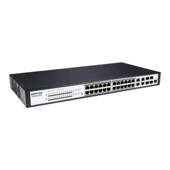
- Page 1 S5300-24P4TS Quick Start Guide V2.0 24-Port Gigabit Ethernet L2+ Switch 24x 10/100/1000BASE-T RJ45 PoE+ Ports @370W, with 4x 1G RJ45/SFP Combo, Support OSPF www.qsfptek.com V2.0 1 / 10...
- Page 2 S5300-24P4TS PoE+ switch is an excellent choice for enterprise network requirements, surveillance systems, and SMBs. We appreciate your decision to select S5300-24P4TS. This manual is intended to help you become acquainted with the switch design and provide instructions for implementing the switches into your network.
-
Page 3: Hardware Overview
Off: no signal transmission Keep the device powered on, press the button “Reset” for 6s, and the Reset system will return to the default setting. If the SYS indicator flickers, the SYS LED system works normally. www.qsfptek.com V2.0 3 / 10... -
Page 4: Installation Requirements
Site Environment Make sure that the workshop is well-ventilated, the heat of electrical devices is well- discharged Avoid damaging devices by following the electrostatic discharge prevention procedure. S5300-24P4TS Hardware Installation Manual www.qsfptek.com V2.0 4 / 10... - Page 5 Mounting the Switch Connecting the Power Plug the AC power cord to the switch power port on the back rear. Connect the other end of the power cord to an AC power source equipment. www.qsfptek.com V2.0 5 / 10...
- Page 6 Insert the SFP module into the SFP port. Plug a fiber patch cable into the SFP transceiver. Connect the other end of the fiber to the device that you want to realize data communication. www.qsfptek.com V2.0 6 / 10...
-
Page 7: Connecting The Management Ports
Connect the DB9 female connector on the other end of the console cable to the serial port on the computer host. Configuring the Switch Configuring the Switch Using the Web-based Interface Step 1: Connect your computer to the switch using an Ethernet cable and open a web browser. www.qsfptek.com V2.0 7 / 10... - Page 8 255.255.255.0. Step 3: Open a web browser and type http://192.168.0.2 in the address bar. Enter the default username and password (admin/admin). Step 4: Click sign-in to access the web-based configuration page. www.qsfptek.com V2.0 8 / 10...
-
Page 9: Troubleshooting
Faults Relative to Power and Cooling System Do the following checkups to help remove the fault: 1. When the power on-off is at the “ON” location, check whether the fan works normally. If the fan www.qsfptek.com V2.0 9 / 10... -
Page 10: Support And Other Resources
Product Warranty S5300 series switches are backed by a 5-year limited warranty supported by QSFPTEK. You are eligible to apply for a return within 14 days and exchange within 90 days of receiving them. For more details about applying qualifications, please live chat or email sales@qsfptek.com...