Table of Contents
Advertisement
Quick Links
www.ti.com
User's Guide
LMR51450 EVM
The LMR51450 evaluation module (EVM) is designed to help customers evaluate the performance of the
LMR51450 synchronous step-down voltage converter. This EVM implements the LMR51450 in a 12-pin WSON
package, as shown in
Table
current with high efficiency and output accuracy in a very small solution size. The EVM provides multiple power
connectors and test points. It also provides a good layout example, which is optimized for EMI and thermal
performance.
CONVERTER
U1
SNVU838A – OCTOBER 2022 – REVISED NOVEMBER 2022
Submit Document Feedback
ABSTRACT
1-1. The EVM is capable of delivering 5 V or 3.3 V output voltage and up to 5 A load
Table 1-1. Device and Package Configurations
IC
LMR51450
LMR51450EVM Front
Copyright © 2022 Texas Instruments Incorporated
PACKAGE
12-pin WSON package 3.0 mm × 3.0 mm × 0.75 mm
LMR51450 EVM
1
Advertisement
Table of Contents

Related Manuals for Texas Instruments LMR51450 EVM


Summary of Contents for Texas Instruments LMR51450 EVM
-
Page 1: Table 1-1. Device And Package Configurations
Table 1-1. Device and Package Configurations CONVERTER PACKAGE LMR51450 12-pin WSON package 3.0 mm × 3.0 mm × 0.75 mm LMR51450EVM Front SNVU838A – OCTOBER 2022 – REVISED NOVEMBER 2022 LMR51450 EVM Submit Document Feedback Copyright © 2022 Texas Instruments Incorporated... -
Page 2: Table Of Contents
Figure 5-6. Bottom 3D view................................. List of Tables Table 1-1. Device and Package Configurations...........................1 Table 6-1. LMR51450 EVM Bill of Materials..........................Trademarks All trademarks are the property of their respective owners. LMR51450 EVM SNVU838A – OCTOBER 2022 – REVISED NOVEMBER 2022 Submit Document Feedback Copyright ©... -
Page 3: Introduction
Figure 1-1. LMR51450 Pin Configuration (Top View) 1.2 LMR51450 Evaluation Module The LMR51450 EVM has the board populated with the LMR51450SDRRR and limiting current to 5 A and comes with auto mode enabled. SNVU838A – OCTOBER 2022 – REVISED NOVEMBER 2022... -
Page 4: Quick Start
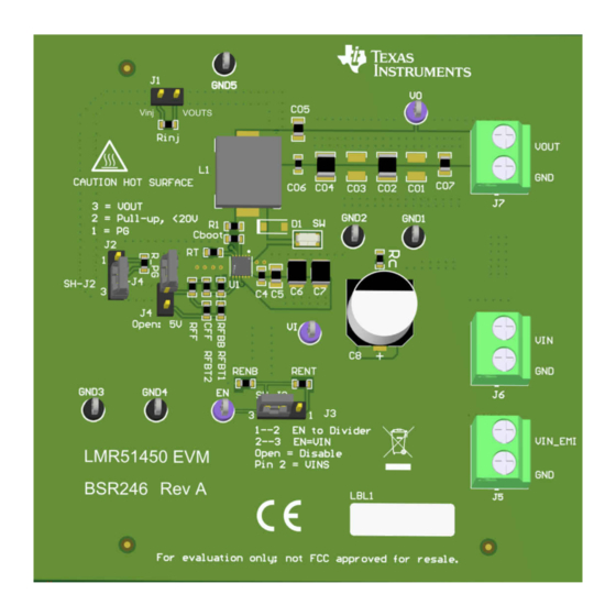
Note that the maximum output current need to derate if ambient temperature is high, especially if device is operated at higher frequency, for example, 1 MHz. Figure 2-1 for connector locations. Figure 2-1. Top View of LMR51450 EVM CAUTION Caution Hot surface. Contact may cause burns. -
Page 5: Detailed Descriptions
Input voltage to input filter of the converter LMR51450 EVM provides the option for the use of input filter. C1, C2 and L4 are placeholders for input filter networks to be populated. If the input filter is desired between the supply and the LMR51450, put C1, C2, and L4 on the board and connect the supply voltage between VIN_EMI and GND_EMI connectors. -
Page 6: Jumpers
J3 This jumper allows the selection of an adjustable input UVLO. J4 This jumper allows the selection of output voltage to be 5 V or 3.3 V. LMR51450 EVM SNVU838A – OCTOBER 2022 – REVISED NOVEMBER 2022 Submit Document Feedback Copyright © 2022 Texas Instruments Incorporated... -
Page 7: Schematic
The bill of materials of the EVM is tabulated in Bill or Materials . In addition, Figure 4-1 shows the corresponding schematic. Figure 4-1. LMR51450 EVM Schematic SNVU838A – OCTOBER 2022 – REVISED NOVEMBER 2022 LMR51450 EVM Submit Document Feedback Copyright © 2022 Texas Instruments Incorporated... -
Page 8: Board Layout
Board Layout www.ti.com 5 Board Layout Figure 5-1 through Figure 5-6 show the board layout for the LMR51450 EVM. The EVM offers resistors, capacitors, and test points to configure the following: • Output voltage • Precision enable • Set frequency The 12-pin WSON package offers a very small solution size. -
Page 9: Figure 5-5. Bottom Layer
Board Layout Figure 5-6. Bottom 3D view Figure 5-5. Bottom Layer SNVU838A – OCTOBER 2022 – REVISED NOVEMBER 2022 LMR51450 EVM Submit Document Feedback Copyright © 2022 Texas Instruments Incorporated... -
Page 10: Bill Of Materials
Bill of Materials www.ti.com 6 Bill of Materials The bill of material is shown in Table 6-1 for the LMR51450 EVM. Table 6-1. LMR51450 EVM Bill of Materials DESIGNATOR DESCRIPTION PART NUMBER MANUFACTURER Printed Circuit Board BSR246 Rev A CAP, CERM, 1000 pF, 50 V,+/- 10%, X7R,... -
Page 11: Revision History
Updated the descriptions to match the Rev. A design..................• Updated the schematic............................• Updated the Top 3D view ...........................8 • Updated the Bill of Materials..........................10 SNVU838A – OCTOBER 2022 – REVISED NOVEMBER 2022 LMR51450 EVM Submit Document Feedback Copyright © 2022 Texas Instruments Incorporated... - Page 12 STANDARD TERMS FOR EVALUATION MODULES Delivery: TI delivers TI evaluation boards, kits, or modules, including any accompanying demonstration software, components, and/or documentation which may be provided together or separately (collectively, an “EVM” or “EVMs”) to the User (“User”) in accordance with the terms set forth herein.
- Page 13 www.ti.com Regulatory Notices: 3.1 United States 3.1.1 Notice applicable to EVMs not FCC-Approved: FCC NOTICE: This kit is designed to allow product developers to evaluate electronic components, circuitry, or software associated with the kit to determine whether to incorporate such items in a finished product and software developers to write software applications for use with the end product.
- Page 14 www.ti.com Concernant les EVMs avec antennes détachables Conformément à la réglementation d'Industrie Canada, le présent émetteur radio peut fonctionner avec une antenne d'un type et d'un gain maximal (ou inférieur) approuvé pour l'émetteur par Industrie Canada. Dans le but de réduire les risques de brouillage radioélectrique à...
- Page 15 www.ti.com EVM Use Restrictions and Warnings: 4.1 EVMS ARE NOT FOR USE IN FUNCTIONAL SAFETY AND/OR SAFETY CRITICAL EVALUATIONS, INCLUDING BUT NOT LIMITED TO EVALUATIONS OF LIFE SUPPORT APPLICATIONS. 4.2 User must read and apply the user guide and other available documentation provided by TI regarding the EVM prior to handling or using the EVM, including without limitation any warning or restriction notices.
-
Page 16: Evm
Notwithstanding the foregoing, any judgment may be enforced in any United States or foreign court, and TI may seek injunctive relief in any United States or foreign court. Mailing Address: Texas Instruments, Post Office Box 655303, Dallas, Texas 75265 Copyright © 2019, Texas Instruments Incorporated... - Page 17 TI products. TI’s provision of these resources does not expand or otherwise alter TI’s applicable warranties or warranty disclaimers for TI products. TI objects to and rejects any additional or different terms you may have proposed. IMPORTANT NOTICE Mailing Address: Texas Instruments, Post Office Box 655303, Dallas, Texas 75265 Copyright © 2022, Texas Instruments Incorporated...