Table of Contents
Advertisement
Quick Links
1
Quick Start Guide
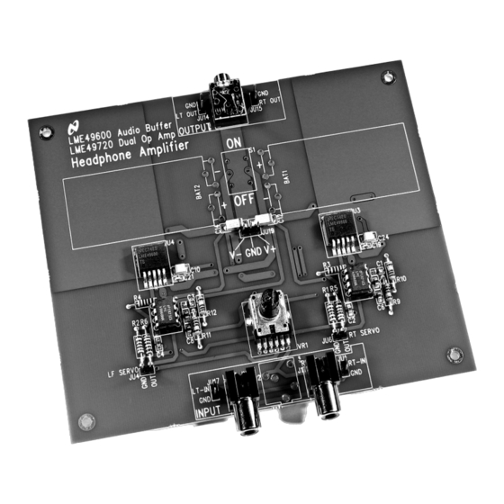
1. Apply a ±2.5V to ±17V power supply's voltage to the respective "V+", "GND" and "V–" pins on JU19.
2. Apply a stereo audio signal to the RCA jacks J1 (Right) and J2 (Left) or jumpers JU1 (Right) and JU17
(Left), observing the signal input pin and the ground (GND) pin. Though not typically installed, a stereo
signal can also be applied to headphone jack HPJ1.
3. Connect a load to JU14 (Left) and another load to JU15 (Right), observing the signal output pin and
the ground (GND) pin. The stereo signal output is also available on the 1/8" stereo headphone jack
located in the board's "OUTPUT" section.
4. Use VR1 to control the output signal amplitude.
5. Apply power. Make measurements. Plug in a pair of headphones. Enjoy.
2
Introduction
To help the user investigate and evaluate the LME49600's performance and capabilities, a fully populated
demonstration board was created. Please click
Connected to an external power supply (±2.5V to ±17V) and a signal source. The LME49600
demonstration board easily demonstrates the amplifier's features.
All trademarks are the property of their respective owners.
SNAA052A – February 2008 – Revised May 2013
Submit Documentation Feedback
AN-1768 LME49600 Headphone Amplifier
here
AN-1768 LME49600 Headphone Amplifier Evaluation Board
Copyright © 2008–2013, Texas Instruments Incorporated
SNAA052A – February 2008 – Revised May 2013
Evaluation Board
for availability. This board is shown in
User's Guide
Figure
1.
1
Advertisement
Table of Contents

Related Manuals for Texas Instruments LME49720NABD


Summary of Contents for Texas Instruments LME49720NABD
- Page 1 Connected to an external power supply (±2.5V to ±17V) and a signal source. The LME49600 demonstration board easily demonstrates the amplifier's features. All trademarks are the property of their respective owners. SNAA052A – February 2008 – Revised May 2013 AN-1768 LME49600 Headphone Amplifier Evaluation Board Submit Documentation Feedback Copyright © 2008–2013, Texas Instruments Incorporated...
-
Page 2: General Description
Operating Conditions Temperature Range –40°C ≤ T ≤ 85°C Amplifier Power Supply Voltage 2.5V ≤ V ±17V AN-1768 LME49600 Headphone Amplifier Evaluation Board SNAA052A – February 2008 – Revised May 2013 Submit Documentation Feedback Copyright © 2008–2013, Texas Instruments Incorporated... -
Page 3: Board Features
1.0 PF Figure 2. LME49600 Demonstration Board Schematic Note: The LM4562, LME49720, or LME49860 can be used. SNAA052A – February 2008 – Revised May 2013 AN-1768 LME49600 Headphone Amplifier Evaluation Board Submit Documentation Feedback Copyright © 2008–2013, Texas Instruments Incorporated... -
Page 4: Pcb Layout Guidelines
AN-1768 LME49600 Headphone Amplifier Evaluation Board SNAA052A – February 2008 – Revised May 2013 Submit Documentation Feedback Copyright © 2008–2013, Texas Instruments Incorporated... -
Page 5: Bill Of Materials
Figure 5 is the bottom layer, Figure 6 is the bottom silkscreen layer. SNAA052A – February 2008 – Revised May 2013 AN-1768 LME49600 Headphone Amplifier Evaluation Board Submit Documentation Feedback Copyright © 2008–2013, Texas Instruments Incorporated... - Page 6 Demonstration Board PCB Layout www.ti.com Figure 3. Top Silkscreen Figure 4. Top Layer AN-1768 LME49600 Headphone Amplifier Evaluation Board SNAA052A – February 2008 – Revised May 2013 Submit Documentation Feedback Copyright © 2008–2013, Texas Instruments Incorporated...
- Page 7 Demonstration Board PCB Layout www.ti.com Figure 5. Bottom Layer Figure 6. Bottom Silk Layer SNAA052A – February 2008 – Revised May 2013 AN-1768 LME49600 Headphone Amplifier Evaluation Board Submit Documentation Feedback Copyright © 2008–2013, Texas Instruments Incorporated...
-
Page 8: Typical Performance
= ±15V, f = 100Hz, 22Hz ≤ BW ≤ 22kHz) = ±3V, f = 1kHz, 400Hz ≤ BW ≤ 22kHz) AN-1768 LME49600 Headphone Amplifier Evaluation Board SNAA052A – February 2008 – Revised May 2013 Submit Documentation Feedback Copyright © 2008–2013, Texas Instruments Incorporated... - Page 9 = ±15V, f = 10kHz, 400Hz ≤ BW ≤ 80kHz) = ±3V, < 10Hz ≤ BW ≤ 80kHz) SNAA052A – February 2008 – Revised May 2013 AN-1768 LME49600 Headphone Amplifier Evaluation Board Submit Documentation Feedback Copyright © 2008–2013, Texas Instruments Incorporated...
-
Page 10: Revision History
= ±9V, < 10Hz ≤ BW ≤ 80kHz) = ±15V, < 10Hz ≤ BW ≤ 80kHz) Revision History Date Description 02/29/08 Initial release. AN-1768 LME49600 Headphone Amplifier Evaluation Board SNAA052A – February 2008 – Revised May 2013 Submit Documentation Feedback Copyright © 2008–2013, Texas Instruments Incorporated... -
Page 11: Important Notice
IMPORTANT NOTICE Texas Instruments Incorporated and its subsidiaries (TI) reserve the right to make corrections, enhancements, improvements and other changes to its semiconductor products and services per JESD46, latest issue, and to discontinue any product or service per JESD48, latest issue. -
Page 12: Texas Instruments
Mouser Electronics Authorized Distributor Click to View Pricing, Inventory, Delivery & Lifecycle Information: Texas Instruments LME49720NABD...