Vulcan-Hart ECO2C Service Manual
Half-size convection ovens electric and gas
Hide thumbs
Also See for ECO2C:
- Installation & operation manual (21 pages) ,
- Catalog of replacement parts (12 pages)
Table of Contents
Advertisement
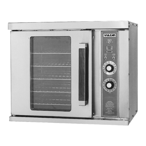
GCO2D Shown
This Manual is prepared for the use of trained Vulcan Service
Technicians and should not be used by those not properly
qualified. If you have attended a Vulcan Service School for this
product, you may be qualified to perform all the procedures
described in this manual.
This manual is not intended to be all encompassing. If you have
not attended a Vulcan Service School for this product, you should
read, in its entirety, the repair procedure you wish to perform to
determine if you have the necessary tools, instruments and skills
required to perform the procedure. Procedures for which you do
not have the necessary tools, instruments and skills should be
performed by a trained Vulcan Service Technician.
Reproduction or other use of this Manual, without the express
written consent of Vulcan-Hart, is prohibited.
A product of VULCAN-HART
Form 24575 (12/96)
SERVICE MANUAL
HALF-SIZE
CONVECTION OVENS
ELECTRIC AND GAS
MODEL
ECO2D
ECO2C
GCO2D
GCO2C
- NOTICE -
ML
ELECTRIC
114570
114572
GAS
114569
114571
LOUISVILLE, KY 40201-0696
Advertisement
Table of Contents

Related Manuals for Vulcan-Hart ECO2C


Summary of Contents for Vulcan-Hart ECO2C
- Page 1 GCO2D Shown This Manual is prepared for the use of trained Vulcan Service Technicians and should not be used by those not properly qualified. If you have attended a Vulcan Service School for this product, you may be qualified to perform all the procedures described in this manual.
-
Page 2: Table Of Contents
ECO2C ........ -
Page 3: General
This manual will cover half-size electric and gas convection ovens that use either a solid state control or an electronic control. Procedures in this manual are applicable to both gas and electric ovens unless specified. GAS OVENS INPUT BTU/HR Natural Single Oven 2500 Stacked Oven 5000 ELECTRIC OVENS 3-PHASE LOADING... -
Page 4: Removal And Replacement Of Parts
Remove the three screws from the left front and loosen the three screws on the right side of the control panel. Pull the panel away from the oven. Unplug the lead wires to the control panel components and disconnect the temperature probe leads. -
Page 5: Control Panel Components
WARNING: UNPLUG UNIT BEFORE SERVICING. Remove the control panel as outlined under "COVERS AND PANELS". Disconnect the wire leads at the component to be replaced. Remove the component. Reverse the procedure to install the new component, then check oven for proper operation. -
Page 6: Blower And/Or Blower Motor
12. Slide the blower onto motor shaft until hub is flush with end of shaft and tighten set screws. 13. Adjust motor position until blower is parallel to oven cavity wall with a spacing of ¼" as outlined under "BLOWER ADJUSTMENT" in "SERVICE PROCEDURES AND ADJUSTMENTS". -
Page 7: Oven Door
OVEN DOOR Removal WARNING: UNPLUG UNIT BEFORE SERVICING. Remove the top front cover as outlined under "COVERS AND PANELS". Remove the door switch lever from the door shaft. Remove the door switch bracket. While supporting the door, remove the bearing, door plate and spacer. -
Page 8: Door Switch
WARNING: SHUT OFF THE GAS BEFORE SERVICING THE UNIT. Remove racks and the right rack support. Remove baffle panel by lifting up and out. Remove the screws that secure the heat exchanger and remove it from the oven. Reverse procedure to install. -
Page 9: Burner (Gas Ovens)
Remove the heat exchanger as outlined under “HEAT EXCHANGER”. Remove the screws from the burner bracket and pull the burner into the oven cavity. Remove the screws that secure the electrodes to the burner bracket. Reverse procedure to install. -
Page 10: Heating Elements (Electric Ovens)
Disconnect the probe leads at the temperature control. Remove probe from the probe guard and push it thru the oven wall into the control panel area. NOTE: When installing, only the metal surface of the probe should be inserted into the probe guard. -
Page 11: Service Procedures And Adjustments
GAS VALVE MUST BE CLOSED. Clamp the wire in such a manner that the end of the wire is 3/16" from the frame of the oven. NOTE: It is critical that the wire be held 3/16" away from the oven or sparking may not occur even though the probe circuits are functioning properly. -
Page 12: Gas Pressure Adjustment
Propane 10 inches W.C. NOTE: If input pressure is below 4.0 (Natural) or 10.5 (Propane) inches W.C., the desired output cannot be obtained and the oven will overate at a lower BTU. SPARK IGNITION CONTROL TEST WARNING: UNPLUG UNIT BEFORE SERVICING. -
Page 13: Electronic Control
See diagram following the table. HOLD KEYS 1 & 3 FUNCTION Calibration Mode CALIBRATE OVEN - Perform Calibration at 350 F Place a thermocouple near the geometric center of the oven cavity. Cycle oven until the cavity temperature stabiliz- es. (usually 3 cycles) Turn the oven off. -
Page 14: Solid State Control Test
SOLID STATE CONTROL TEST NOTE: Oven temperature must be below 450 F. Remove the screws from the control panel and pull the control panel away from the oven to access the control wiring. Place a thermocouple in the geometric center of the oven cavity. -
Page 15: Door Switch Adjustment
If the average temperature differs more than 10 degrees F from the dial settings: Pencil mark the knob pointer position as a reference point on the control panel next to the dial plate. Remove the temperature control knob. Loosen the two dial plate mounting screws and the temperature control mounting nut. -
Page 16: Door Reversal
10. Adjust the door as outlined under “DOOR ADJUSTMENT”. 11. Adjust the door switch as outlined under “DOOR SWITCH ADJUSTMENT”. 12. Replace the top front cover and check the oven for proper operation. -
Page 17: Door Adjustment
Remove rack and rack supports. Remove baffle panel by lifting up and out. Check the blower. It should be ¼" away from and parallel to the oven wall. If not, proceed to step 4. Remove the right side panel as outlined under “COVERS AND PANELS”. -
Page 18: Electrical Operation
BLOWER MOTOR ... . Circulates air inside oven cavity. (Contains centrifugal switch for gas ovens) DOOR SWITCH ....Allows heating of oven, only when the doors are closed. -
Page 19: Component Location
HALF-SIZE CONVECTION OVENS - ELECTRICAL OPERATION COMPONENT LOCATION... -
Page 20: Sequence Of Operation
SEQUENCE OF OPERATION Ignition Module 24VAC supplied to ignition module as described under oven sequence of operation 15 second prepurge period No-ignition light is on Cavity blower motor removes any residual gas from combustion chamber 10 second spark period Gas valve energized... - Page 21 Solid State Timer (Gas) NOTE: Use GCO2D Schematic NOTE: The timer is not connected to the heating circuit and will not prevent the oven from heating when time expires. Power switch on Time dialed into timer, contacts 1/3 close.
- Page 22 Display counts up time and flashes "hold" Oven continues to cycle at hold temperature until oven is turned off or the hold function is turned off. NOTE: The blower motor and gas valve are de- energized when the door is opened while the oven is in the hold mode.
-
Page 23: Electric Oven
Solid State Timer (Elec) NOTE: Use ECO2D Schematic NOTE: The timer is not connected to the heating circuit and will not prevent the oven from heating when time expires. Power switch on Time dialed into timer, contacts 1/3 close. - Page 24 12 low); wire #13/7; J1-7; wire #7/37; power switch Electronic Control (Elec) NOTE: Use ECO2C Schematic NOTE: A combination of terminal numbers and wire numbers will be used to describe the circuit paths. The complete path will be described when a component is energized.
- Page 25 Display counts up time and flashes "hold" Oven continues to cycle at hold temperature until oven is turned off or the hold function is turned off. NOTE: The blower motor and heating elements are de-energized when the door is opened and the oven is in the hold mode.
-
Page 26: Schematics Gas Ovens
HALF-SIZE CONVECTION OVENS - ELECTRICAL OPERATION SCHEMATICS GAS OVENS GCO2D... -
Page 27: Gco2C
HALF-SIZE CONVECTION OVENS - ELECTRICAL OPERATION GCO2C... -
Page 28: Wiring Diagram - Gas Ovens
HALF-SIZE CONVECTION OVENS - ELECTRICAL OPERATION WIRING DIAGRAM - GAS OVENS GCO2D - Control Section... - Page 29 HALF-SIZE CONVECTION OVENS - ELECTRICAL OPERATION GCO2D - Oven Section...
-
Page 30: Gco2C
HALF-SIZE CONVECTION OVENS - ELECTRICAL OPERATION GCO2C - Control Section... - Page 31 HALF-SIZE CONVECTION OVENS - ELECTRICAL OPERATION GCO2C - Oven Section...
-
Page 32: Schematic-Electric Ovens
HALF-SIZE CONVECTION OVENS - ELECTRICAL OPERATION SCHEMATIC-ELECTRIC OVENS ECO2D... -
Page 33: Eco2C
HALF-SIZE CONVECTION OVENS - ELECTRICAL OPERATION ECO2C... -
Page 34: Wiring Diagram Electric Ovens
HALF-SIZE CONVECTION OVENS - ELECTRICAL OPERATION WIRING DIAGRAM ELECTRIC OVENS ECO2D - Control Section... - Page 35 HALF-SIZE CONVECTION OVENS - ELECTRICAL OPERATION ECO2D - Oven Section...
-
Page 36: Eco2C
HALF-SIZE CONVECTION OVENS - ELECTRICAL OPERATION ECO2C - Control Section... - Page 37 HALF-SIZE CONVECTION OVENS - ELECTRICAL OPERATION ECO2C - Oven Section...
-
Page 38: Troubleshooting
ELECTRIC OVENS SYMPTOM No power to oven controls. No oven operation; power to controls. Blower motor operates when oven is heating, but not in cooldown. Blower motor does not operate, oven heats. Oven is slow to heat or not hot enough. -
Page 39: Gas Ovens
No power to oven controls. No oven operation; power to controls. Gas does not ignite; no spark. Oven is slow to heat or not hot enough. Gas ignites, but will not maintain flame. Sparks but does not ignite. Electronic control does not function. - Page 40 Form 24575 (12/96) Printed in U.S.A.