Denon POA-3012CI - Powerful and Precision-engineered Multi-Channel Power Amplifier Manual
- Service manual (72 pages) ,
- Owner's manual (39 pages) ,
- Control protocol (10 pages)
Advertisement
- 1 Getting Started
- 2 Part Names and Functions
- 3 Connections
- 4 Setup
- 5 Operations
- 6 Troubleshooting
- 7 Specifications
- 8 IMPORTANT SAFETY INSTRUCTIONS
- 9 Documents / Resources
Getting Started
Accessories
Check that the following parts are supplied with the product.
- Owner's manual: 1
- Warranty (for North America model only): 1
- Service station list: 1
- Power cord: 1

Cord length:- Model for the North America:.6.6 ft / 2.0 m
- Europe model: 5.2 ft / 1.6 m

Cautions on Handling
- Before turning the ON/STANDBY switch on
Check once again that all connections are correct and that there are no problems with the connection cables. - Power is supplied to some of the circuitry even when the unit is set to the standby mode. When traveling or leaving home for long periods of time, be sure to unplug the power cord from the power outlet.
- About condensation
If there is a major difference in temperature between the inside of the unit and the surroundings, condensation (dew) may form on the operating parts inside the unit, causing the unit not to operate properly.
If this happens, let the unit sit for an hour or two with the power turned off and wait until there is little difference in temperature before using the unit. - Cautions on using mobile phones
Using a mobile phone near this unit may result in noise. If so, move the mobile phone away from this unit when it is in use. - Moving the unit
Turn off the power and unplug the power cord from the power outlet. Next, disconnect the connection cables to other system units before moving the unit. - Note that the illustrations in these instructions may differ from the actual unit for explanation purposes.
Cautions on Installation
 Note:
Note:
For proper heat dispersal, do not install this unit in a confined space, such as a bookcase or similar enclosure.

Part Names and Functions
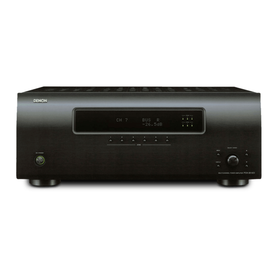
Front Panel

- Power operation button
(ON / STANDBY) - Power indicator
- Display
- Information display
Displays present status information and Setup menu etc.,
- Information display
- ZONE select buttons
- ZONE operation mode indicators
- SETUP button
- DISPLAY button
- SELECT / ENTER knob
![]() (Down) button
(Down) button![]() (Up) / RETURN button
(Up) / RETURN button
Rear Panel

- ETHERNET connector
- RS-232C connector
- Speaker terminals
(SPEAKER SYSTEMS) - AC inlet (AC IN)
- AUDIO INPUT connectors
- TRIGGER IN jacks
- MASTER TRIGGER OUT jack
- BUS INPUT connectors
- BUS OUTPUT connectors
- MASTER TRIGGER IN jack
Connections
Connections for all compatible audio signal formats are described in this owner's manual. Please select the types of connections suited for the equipment you are connecting.
With some types of connections, certain settings must be made on the POA-3012CI. For details, refer to the instructions for the respective connection items below.
NOTE
- Do not plug in the power cord until all connections have been completed.
- When making connections, also refer to the operating instructions of the other components.
- In the case of Bus input / output connections, be sure to connect the left and right channels properly (left with left, right with right).
- Do not bundle power cords together with connection cables. Doing so can result in humming or noise.
Preparations
Before Connecting
The POA-3012CI incorporates six sets of 2-channel amplifier from ZONE1 to ZONE6.
The same audio signal can be output from all ZONE or separate signals can be output from each ZONE. The POA-3012CI also supports BRIDGED output.
Before making the connections, determine the input signals and output signals for each ZONE and then set up the POA-3012CI in accordance with the following procedure.
Input Setting
- Select the input terminal to use.
Each Zone input connectors or BUS input connectors. - Connect the external device to the input terminal.
"INPUT SELECT" - Set the input source.
"Input Connection"
Output Setting
- Select the speaker output method.
NORMAL output or BRIDGED output. - Connect the speaker cable.
"Speaker Connections" - Set the output channel.
"OPERATION MODE"
Cables Used for Connections
Select the cables according to the equipment being connected.
Audio cables
Audio input connections

Pin-plug cable
Bus input/output connections (stereo)

Stereo pin-plug cable
Network connections

Ethernet cable
Speaker connections

Speaker cable
Signal direction
Audio signal:

Speaker Connections
Connection Method When Outputting 2 Channels From One ZONE

Connection Method for BRIDGED Output
- In BRIDGED mode, one channel is output from one ZONE.
- To set BRIDGED mode, select "BRIDGED" as the "OPERATION MODE" on the "Main Setup" menu.
- When BRIDGED out putting a signal input to the AUDIO INPUT terminal, input to an even-numbered input terminal.
- To select a signal for BRIDGED output from among the signals ("L", "R", "L+R") input to the BUS INPUT terminal, use "INPUT SELECT" on the "Main Setup" menu.

Connecting the Speaker Cables
Carefully check the channel numbers and + (red) and – (black) polarities on the speakers being connected to the POA-3012CI, and be sure to interconnect the channels and polarities correctly.
- Peel off about 0.03 ft/10 mm of sheathing from the tip of the speaker cable, then either twist the core wire tightly or terminate it.
![]()
- Turn the speaker terminal counterclockwise to loosen it.
![]()
- Insert the speaker cable's core wire to the hilt into the speaker terminal.
![]()
- Turn the speaker terminal clockwise to tighten it.
![]()


When using a banana plug (for North America model)

Tighten the speaker terminal firmly before inserting the banana plug.
NOTE
- Use speakers with an impedance of 4 to 16 Ω/ohms. Use a 8 to 16 Ω/ohms speaker for BRIDGED output.
- Connect the speaker cables in such a way that they do not stick out of the speaker terminals. The protection circuit may be activated if the core wires touch the rear panel or if the + and – sides touch each other ("Protection circuit").
- Never touch the speaker terminals while the power supply is connected. Doing so could result in electric shock.
Protection circuit
If speakers with an impedance lower than specified (for example 4 Ω/ ohms speakers / NORMAL MODE) are used for an extended period of time with the volume turned up high, the temperature may rise, activating the protection circuit.
There are 2 kind of protection circuits in POA-3012CI.
- Protection circuit for individual Amplifier (Zone 1 ~ 6)
This protection circuit detects over load condition of the amplifier circuit.
When the protection circuit is activated, the speaker output of individual Amplifier (Zone 1 ~ 6) is shut off, and the Zone operation mode indicator for protected Zone No. flashes red. If this happen, unplug the power cord, then check the speaker cable and input cable connections. - Temperature rise protection circuit in the chassis.
This protection circuit detects temperature rising in the chassis. When the protection circuit is activated, the power source for all Amplifier circuits is shut off, and the power indicator flashes red. If this happen, it may be extremely hot in the chassis, unplug the power cord.
Wait for it too cool off and improve ventilation around it.
Once this is done, plug the power cord back in and turn the set's power back on.
If the protection circuit is activated again even though there are no problems in the ventilation around the set nor in the connections, the set may be damaged. Turn the power off, then contact a DENON service center.
Input Connections
BUS INPUT Connections
- To play signals input to the BUS INPUT terminal, select the channel using "INPUT SELECT" on the "Main Setup" menu.
- When "BUS L+R" is used, signals input to BUS INPUT L and R are mixed and output as monaural.

 Signals input from the BUS INPUT are output from the BUS OUTPUT terminal. These signals can be output to the BUS INPUT terminal of another POA-3012CI unit.
AUDIO INPUT Connections
When Using in NORMAL MODE
To play signals input to the AUDIO INPUT terminal, use "INPUT SELECT" on the "Main Setup" menu to set each channel to AUX.
[Example]
Connect the left and right channels from audio source to audio inputs of arbitrary numbers.

When Using in BRIDGED MODE
Input BRIDGED output signals to an even-numbered input terminal.
[Example]
Connect the left and right channels from audio source to audio inputs of arbitrary numbers.

Connections to Other Devices
ETHERNET Connections

Required System
- Broadband Internet Connection
A broadband line connection to the Internet is required in order to use the POA-3012CI's firmware update. - Modem
This is a device that is connected to the broadband line to communicate with the Internet. Some are integrated with the router. - Router
- When using the POA-3012CI, we recommend you use a router equipped with the following functions:
- Built-in DHCP (Dynamic Host Configuration Protocol) server This function automatically assigns IP addresses on the LAN.
- Built-in 100 BASE-TX switch
When connecting multiple devices, we recommend a switching hub with a speed of 100 Mbps or greater.
- When using the POA-3012CI, we recommend you use a router equipped with the following functions:
- Ethernet Cable (CAT-5 or greater recommended)
- The POA-3012CI does not come with an Ethernet cable.
- Some flat type Ethernet cables are easily affected by noise. We recommend using a normal type cable.
- If the sound is broken in an environment in which there is much power supply noise from electric products or in a noisy network environment, use a shielded type Ethernet cable (For North America model).
- For the Ethernet cable, used a shielded twisted pair (STP) cable. Do not use an unshielded twisted pair (UTP) cable, as it may exceed noise standard limits (For Europe model).
- Computer
A computer with the following specifications is required to use a server:- OS
Windows® XP Service Pack2, Windows Vista - Internet browser
Microsoft Internet Explorer 5.01 or later - LAN port
- OS
For connections to the Internet, contact an ISP (Internet Service Provider) or a computer shop.
NOTE
- A contract with an ISP is required to connect to the Internet.
No additional contract is needed if you already have a broadband connection to the Internet. - The types of routers that can be used depend on the ISP. Contact an ISP or a computer shop for details.
- Others
- If you have an Internet provider contract for a line on which network settings are made manually, make the settings at "Network Setup".
- With the POA-3012CI, it is possible to use the DHCP and Auto IP functions to make the network settings automatically.
- When using a broadband router (DHCP function), the POA-3012CI sets the IP address, etc., automatically.
When using the POA-3012CI connected to a network with no DHCP function, make the settings for the IP address, etc., at "Network Setup". - The POA-3012CI is not compatible with PPPoE. A PPPoE-compatible router is required if you have a contract for a line of the type with which the PPPoE is set.
External Controller
RS-232C connector

This connector is used for an external controller.
* If you wish to control the POA-3012CI from an external controller using the RS-232C connector, perform the operation below beforehand.
- Turn the POA-3012CI's power.
- Turn off the POA-3012CI's power from the external controller.
- Check that the POA-3012CI is in the standby mode.
Trigger output jack

The power of an external device equipped with a trigger input jack can be turned on and off in association with operations on the POA-3012CI.
- Output level: 250 mA / 12 V Check the trigger input conditions of the connected device.
- If the trigger input level of the connected device is higher than 250 mA / 12 V and depending on the short-circuiting conditions, the POA-3012CI's protection circuit may be activated, in which case "TRIGGER OUT OVER LOAD" appears on the display. If this happens, turn off the POA- 3012CI's power and disconnect the connected device.
Master trigger input jack

The "POWER CONFIGURATION" setting is valid at the time of a "MASTER TRIGGER".
Voltage input to the MASTER TRIGGER input terminal and operating status of the POA-3012CI:
At DC 3 ~ 30 V: ON
At DC 0 V: STANDBY
ZONE trigger input jack

The ZONE TRIGGER ON MODE setting is valid at the time of a "TRIGGER IN".
Voltage input to the TRIGGER IN input terminal and operating status of the power amplifier of each ZONE:
At DC 3 ~ 30 V: ON
At DC 0 V: STANDBY
Connecting the Power Cord
Wait until all connections have been completed before connecting the power cord.

- North America model: To household power outlet (AC 120 V, 60 Hz)
- Europe model: To household power outlet (AC 230 50 Hz)
NOTE
Insert the AC plugs securely. Incomplete connections could cause noise.
Once Connections are Completed
Turning the Power On
See "Operations → Turning the Power On".
Setup

Example of Display of Default Values
In lists of selectable items or adjustable ranges, the item surrounded by a border is the default value:

Operations
For all settings, refer to "Menu map".
For details of individual settings refer to the explanations of settings.
- Press the SETUP button.
The POA-3012CI enters the "SETUP" mode and the first level menu is displayed.
The selected item blinks. - Select the required item on the menu and set it.
Using the menu
- To select the item to be set
Turn the SELECT / ENTER knob until the item you want to set appears. - To enable lower level menu items to be displayed
Press the SELECT / ENTER knob or the![]() button.
button. - To return to higher level menu items
Press the![]() / RETURN button.
/ RETURN button. - To confirm selected item
Press the SELECT / ENTER knob. - To exit SETUP mode
Press the SETUP button until the display returns to normal.
If you want to configure the settings for a specific ZONE, press the ZONE 1 ~ 6 button for the ZONE concerned and configure the settings.
- In this case, the setting item of another ZONE is not displayed.
- To configure the settings for "DIMMER MODE" and "POWER CONFIGURATION", use the SETUP button to select "Main Setup" mode.
Menu Map


Main Setup
Menu tree

VOLUME CONTROL
Sets the volume level for each channel.
[Selectable Channels]
Channels which can be set in each mode.
| NORMAL MODE | BRIDGED MODE | |
| CH 1 | ◯ | ╳ |
| CH 2 | ◯ | ◯ |
| CH 3 | ◯ | ╳ |
| CH 4 | ◯ | ◯ |
| CH 5 | ◯ | ╳ |
| CH 6 | ◯ | ◯ |
| CH 7 | ◯ | ╳ |
| CH 8 | ◯ | ◯ |
| CH 9 | ◯ | ╳ |
| CH 10 | ◯ | ◯ |
| CH 11 | ◯ | ╳ |
| CH 12 | ◯ | ◯ |
Default: NORMAL MODE
◯: Setting possible
╳: Setting not possible
[Variable range]

INPUT SELECT
Sets the input terminal for each channel.
[Selectable Channels]
For details of the channels which can be set in each mode, see [Selectable Channels] in "VOLUME CONTROL".
[Selectable items]
 : AUDIO INPUT terminal of each ZONE.
 : L terminal of BUS INPUT
 : R terminal of BUS INPUT
 : L and R terminals of BUS INPUT. Inputs a L and R mixed mono signal.
LOW CUT FILTER
Cuts the low frequency component of each channel.
Turn this "ON" when there is a high volume of low frequency sound.
[Selectable Channels]
For details of the channels which can be set in each mode, see [Selectable Channels] in "VOLUME CONTROL".
[Selectable items]
 : Low frequency component is cut.
 : Low frequency component is not cut.
OPERATION MODE
Sets the output method for channels in each ZONE.
[Selectable Channels]
Sets each of the following channel pairs.
| NORMAL MODE | BRIDGED MODE | |
| CH 1 & 2 | ◯ | ◯ |
| CH 3 & 4 | ◯ | ◯ |
| CH 5 & 6 | ◯ | ◯ |
| CH 7 & 8 | ◯ | ◯ |
| CH 9 & 10 | ◯ | ◯ |
| CH 11 & 12 | ◯ | ◯ |
Default: NORMAL MODE
[Selectable items]
 : 2-channel output
 : BRIDGED-channel output (1-channel output)
- During NORMAL MODE, ZONE operations mode indicators are lit green.
- During BRIDGED MODE, ZONE operations mode indicators are lit orange.
NOTE
The method of connecting speakers differs for each mode. Connect the speakers in accordance with the mode setting. For details, refer to "Speaker Connection".
ZONE TRIGGER ON MODE
Sets the operating specifications for the power amplifiers of each ZONE.
[Selectable Channels]
For details of the channels which can be set in each mode, see [Selectable Channels] in "OPERATION MODE".
[Selectable items]
 : The power amplifier operates constantly.
 : The power amplifier operates when trigger input is detected.
When trigger input is not detected, it remains in standby mode.
 : The power amplifier operates when an audio signal is input.
If no input is received for a period of 10 minutes, it switches to standby mode.
 : Turns the power amplifier off.
The POA-3012CI accepts +3 ~ 30V trigger input.
DIMMER MODE
Adjust display brightness of the POA-3012CI.
[Selectable items]
 : Normal display brightness.
 : Reduced display brightness.
 : Very low display brightness.
 : Display is off unless controls are operated.
When setting to "Dim", "Dark" and "OFF", the display brightness changes to "Bright" for about 3 seconds during the operation before reverting to the set brightness.
POWER CONFIGURATION
Select the method for turning on the POA-3012CI.
[Selectable items]
 : Operate with the ON/STANDBY button only.
 : Operate from an external device via Ethernet or RS-232C input.
 : Operate by detection of a trigger signal input to the MASTER TRIGGER input terminal.
- Turns on when a signal is detected.
- If no input is received for a period of 10 minutes, it switches to standby mode.
- The POA-3012CI accepts +3 ~ 30 V trigger input.
- Even when "ON LINE" or "MASTER TRIGGER" has been set, power source operation is possible by means of ON / STANDBY button.
Network Setup
Make network settings.
Menu tree

- If you are using a broadband router (DHCP function), there is no need to make the settings at "Setting the IP Address" and "Setting the Proxy", since the DHCP function is set to "ON" in the POA-3012CI's default settings.
- If the POA-3012CI is being used connected to a network without the DHCP function, the network settings must be made. In this case, some knowledge of networks is required. For details, consult a network administrator.
- If you cannot connect to the Internet, recheck the connections and settings.
- If you do not understand about Internet connection, contact your ISP (Internet Service Provider) or the store from which you purchased your computer.
- DHCP (Dynamic Host Configuration Protocol) :
These are systems by which the IP address and other network settings are automatically set for the POA-3012CI, computer, broadband router and network devices. - DNS (Domain Name System) :
This is a system for converting the domain names used when browsing Internet sites (for example, "www.denon.jp") into the IP addresses actually used for communications (for example, "202.221.192.106").
Network Information
Display network information
[Items to be checked]

Network Setup
Make settings for wired LAN.
Wired LAN settings
Use this procedure to configure the Wired LAN settings.
- Connect the LAN cable
- Turn on the POA-3012CI
POA-3012CI performs automatic network setup due to the DHCP function.
When connecting to a network that has no DHCP function, perform the setting in step 3. - Set the IP address at the menu "Network Setup"
![]()

- Select "DHCP" and press the SELECT / ENTER knob.
- Turn the SELECT / ENTER knob to set "DHCP" to "OFF", then press the SELECT / ENTER knob. The DHCP function is disabled.
- Use the following buttons to input the address and press the SELECT/ENTER knob.
* Button functions when entering address
SELECT/ENTER knob:
Turn: Select
Press: Confirm
![]() button: Cursor to right
button: Cursor to right
![]() button: Cursor to left
button: Cursor to left
ZONE 6 button: Setting during address entry
ZONE 5 button: Cancel entry
IP Address:
Set the IP address within the ranges shown below. The Network function cannot be used if other IP addresses are set.
CLASS A: 10.0.0.0 ~ 10.255.255.255
CLASS B: 172.16.0.0 ~ 172.31.255.255
CLASS C: 192.168.0.0 ~ 192.168.255.255
Subnet Mask:
When connecting an xDSL modem or terminal adapter directly to the POA-3012CI, input the subnet mask indicated in the documentation supplied by your provider. Normally input 255.255.255.0.
Default Gateway:
When connected to a gateway (router), input its IP address.
Primary DNS Secondary DNS:
If there is only one DNS address indicated in the documentation supplied by your provider, input it at "Primary DNS". If there are two or more DNS addresses, input the first one at "Secondary DNS".
- Press the SELECT / ENTER knob. Setup is complete.
* When connecting to the network via a Proxy server, select "Proxy" and press the SELECT / ENTER knob ( "Proxy settings").
Proxy settings
Make this setting when connecting to the Internet via a proxy server.
- Select "Proxy".
![]()
- Set "ON".
![]()
- Selecting the input method
Example) Address
![]()
- Input the address or domain name.
![]()
- Select "Port".
- Input the port number.
![]()


- Select menu "Network Setup" – "Network Setup" – "Proxy" and press the SELECT / ENTER knob.
- Turn the SELECT / ENTER knob to set "Proxy" to "ON" and press the SELECT / ENTER knob. The proxy server is enabled.
- Turn the SELECT / ENTER knob to select the proxy server input method, and then press the
![]() button.
button.
[Selectable items]
![]() : Select when inputting by address.
: Select when inputting by address.
![]() : Select when inputting by domain name.
: Select when inputting by domain name.
[Characters that can be input]
![]()
- Use the following buttons to input the proxy server address or domain name and press the SELECT / ENTER knob.
* Button functions when entering address
SELECT / ENTER knob:
Turn: Select
Press: Confirm
![]() button: Cursor to right
button: Cursor to right
![]() button: Cursor to left
button: Cursor to left
ZONE 6 button: Setting during address entry
ZONE 5 button: Cancel entry
DISPLAY button:
Character insert / delete / overwrite
Cursor![]() : Character insert
: Character insert
Cursor![]() : delete
: delete
Cursor![]() : overwrite
: overwrite
When "Address" is selected in step 3: Input the address
When "Name" is selected in step 3: Input the domain name - Turn the SELECT/ENTER knob to select the "Port" and press SELECT/ENTER knob.
- Use the above buttons to input the proxy server port number and press the SELECT/ENTER knob.
- Press the SELECT/ENTER knob.
Setup is complete.


Option Setup
Make various other settings.
Menu tree

Setup Lock
Protect settings from inadvertent change.
[Selectable items]
 : Turn protection on.
 : Turn protection off.
To cancel the setting, press the SETUP button to re-display the "Setup Lock", then change the setting to "OFF".
Maintenance
This sets the function for maintenance by a DENON service person or installer. (For professional use only.)
This function allows a DENON service person or installer to check the POA-3012CI's status and make settings via the Internet.
NOTE
Only use this function if so instructed by a DENON service person or installer.
Firmware Update
Update the firmware of the multi channel power amplifier.
Update Check
You can check for firmware updates. You can also check approximately how long it will take to complete an update.
Update Start
Execute the update process. When updating starts, the power indicator lights red. "Updating ***" is shown on the display during updating. Once updating is completed, "Updating complete" is displayed.
"Latest firmware" is displayed when the firmware is the latest version.
* If the display reads as shown below, check the settings and network environment, then update again.
| Display | Description |
| Updating failed | Updating failed. |
| Login failed | Failure to log into server. |
| Server is busy | Server is busy. Wait a while then try again. |
| Connection fail | Failure connecting to server. |
NOTE
- Connection to the network and specific settings are required to update the firmware.
- Do not turn off the power until updating is completed.
- Normally there is no need to use this function, aside from the cases described below.
- The Firmware Update function is only used for updating the firmware (free or for a charge) via the Internet, for example for the purpose of adding functions to the POA-3012CI in the future.
- Information regarding the Firmware Update function will be announced on the DENON web site each time related plans are defined.
- A broadband connection to the Internet is required to use this function.
- Even with a broadband connection to the Internet, approximately 13 min is required for the updating procedure to be completed. Once updating starts, normal operations on the POA-3012CI cannot be performed until updating is completed. Furthermore, updating the firmware may reset the backup data for the parameters, etc., set for the POA-3012CI.
Operations

Turning the Power On
Press the ON / STANDBY button.
The power indicator fl ashes green and the power turns on.
* The signal input to each channel is output from the speaker terminal of each channel.
* The setting status of each channel is indicated on the display.
* Turn the SELECT/ENTER knob to change the channel displayed.

(No display when in "NORMAL MODE")
To return to STANDBY
Press the ON / STANDBY button again.
The power indicator lights red.
NOTE
- When the "POWER CONFIGURATION" is set to "MASTER TRIGGER", the device will automatically enter the standby status when no trigger input is detected for a period of 10 minutes.
- When the "POWER CONFIGURATION" is set to "ON LINE", send a standby command to the ETHERNET terminal or the RS-232C terminal of the POA-3012CI.
- Power continues to be supplied to some of the circuitry even when the power is in the standby mode. When leaving home for long periods of time or when traveling, unplug the power cord from the power outlet.
Check the Status of Each Channel
- Press the DISPLAY button.
* Zone status is indicated on the bottom line of the display.
* Turn the SELECT / ENTER knob to change the display as follows.
![]()
- Press the DISPLAY button again.
* System status is indicated on the bottom line of the display.
* Turn the SELECT / ENTER knob to change the display as follows.
POWER CONFIG ↔ DIMMER

To Return to the Regular Display
Press the ![]() / RETURN button until the display returns to normal.
/ RETURN button until the display returns to normal.
Other Operations
Other Operations During Playback
- To Adjust the Volume
Refer to "VOLUME CONTROL" on the "Main Setup" menu. - To Switch Input Setting
Refer to "INPUT SELECT" on the "Main Setup" menu. - To Reduce the Low Frequency Volume
Refer to "LOW CUT FILTER" on the "Main Setup" menu.
Operating the POA-3012CI Using a Browser (Web control)
This function lets you operate the POA-3012CI using Internet Explorer.
- Check the POA-3012CI's IP Address.
"Network Setup" – "Network Information" - Input the POA-3012CI's IP Address in Internet Explorer.
For example, if the IP address is "10.3.18.90", enter http://10.3.18.90. - If the top menu is displayed, click "Setup Menu".

- When the "Setup Menu" is displayed, click on the menu you want to operate.
![]()


- Click the menu
CHANNEL SETUP (Example: 1)
SYSTEM SETUP (Example: 2)
WARNING AND PROTECTION DATA (Example: 3)
AUDIO SIGNAL AND TRIGGER INPUT (Example: 4)
OPTION SETUP (Example: 5)
- Click "SAVE" when you want to save settings, and click "LOAD" when you want to call settings.
Becomes each operation screen.
- Operate.
[Example: 1] Channel Setup Screen
![Operate - [Example: 1] - Channel Setup Screen]( "Denon - POA-3012CI - Operate - [Example: 1] - Channel Setup Screen")
![Operate - [Example: 1] - Channel Setup Screen](http://static-data2.manualslib.com/pdf7/337/33699/3369849-denon/images/denon-poa-3012ci-operate-example-1-channel-setup-screen-dae74.png "Denon - POA-3012CI - Operate - [Example: 1] - Channel Setup Screen")
*: Normally, there is a change to the latest information each time you operate. When operated from the main unit, click because the screen is not updated.
[Example: 2] System Setup Screen
![Operate - [Example: 2] - System Setup Screen](http://static-data2.manualslib.com/pdf7/337/33699/3369849-denon/images/denon-poa-3012ci-operate-example-2-system-setup-screen-d08a8.png "Denon - POA-3012CI - Operate - [Example: 2] - System Setup Screen")
[Example: 3] Warning and Protection Data Screen
![Operate - [Example: 3] - Warning and Protection Data Screen](http://static-data2.manualslib.com/pdf7/337/33699/3369849-denon/images/denon-poa-3012ci-operate-example-3-warning-and-protection-e687f.png "Denon - POA-3012CI - Operate - [Example: 3] - Warning and Protection Data Screen")
[Example: 4] Audio Signal and Trigger Input Screen
![Operate - [Example: 4] - Audio Signal and Trigger Input Screen](http://static-data2.manualslib.com/pdf7/337/33699/3369849-denon/images/denon-poa-3012ci-operate-example-4-audio-signal-and-trigger-8184d.png "Denon - POA-3012CI - Operate - [Example: 4] - Audio Signal and Trigger Input Screen")
[Example: 5] Option Setup Screen
![Operate - [Example: 5] - Option Setup Screen](http://static-data2.manualslib.com/pdf7/337/33699/3369849-denon/images/denon-poa-3012ci-operate-example-5-option-setup-screen-9018c.png "Denon - POA-3012CI - Operate - [Example: 5] - Option Setup Screen")
To use the web control function, set the menu "Main Setup" – "POWER CONFIGURATION" – "ON LINE".
NOTE
- To perform web control, you must connect a web control device such as a PC to the same network as the POA-3012CI.
- With web control, some network settings, etc., cannot be set.
- When updating firmware, settings made by the web controller may be reset.
Resetting the Microprocessor
Perform this procedure if the display is abnormal or if operations cannot be performed. When the microprocessor is reset, all the settings are reset to their default values.
- Unplug the power cord from the power outlet.
- Turn the power on (or connect the power cord to the power outlet) while simultaneously pressing the ZONE 5 and DISPLAY buttons.
- When all Zone operation mode indicators are illuminated in red and " *EEPROMINIT.*" is displayed, release finger from two buttons.
If in step 3 the could not be start over from step 1.
Troubleshooting
Check the following before assuming there is a problem with the set:
- Are all connections proper?
- Is the set being operated as described in the owner's manual?
- Are the speakers and input components being operated properly?
If the set does not seem to be operating properly, check the points listed below. If these points do not apply, the set may be damaged. Turn off the power immediately and contact your store of purchase.
| Symptom | Cause | Countermeasure |
| When the power is turned on, the power indicator does not light and no sound is produced. |
|
|
| The power indicator lights but no sound is produced. |
|
|
|
| |
|
| |
|
| |
|
| |
|
| |
|
| |
|
|
Specifications
| Rated output: | 12-channel driving, NORMAL operation: 6-channel driving, BRIDGED operation: |
| Total harmonic distortion: | 0.05% (Rated output: –3 dB, 8 Ω/ohms, 1 kHz |
| Output terminals: | Speaker 4 ~ 16 Ω/ohms (NORMAL operation) Speaker 8 ~ 16 Ω/ohms (BRIDGED operation) |
| Input sensitivity / Input impedance: | 550 mV / 47 kΩ/kohms (NORMAL operation) 275 mV / 47 kΩ/kohms (BRIDGED operation) |
| Gain: | 29 dB (NORMAL operation) 35 dB (BRIDGED operation) |
| Frequency response: | 5 Hz ~ 40 kHz (Low cut filter: OFF) |
| S/N ratio: | 95 dB (input terminals short-circuited, with A-weightied network) |
| Low cut filter: | Cut off frequency 80 Hz (–12 dB/oct. Low cut filter: ON) |
| Trigger in level: | 3 ~ 30 V DC |
| Trigger out level: | 12 V DC, 250 mA MAX |
| Power Supply: | AC 120 V, 60 Hz (North America model) / AC 230 V, 50Hz (Europe model) |
| Power Consumption: | 2.5 A (North America model) / 230 W (Europe model) Standby: 0.5 W or less (When the "POWER CONFIGURATION" is set to "POWER BUTTON") |
| Maximum external dimension: | 434 (W) x 171 (H) x 410 (D) mm (17-3/32" x 6-47/64" x 16-9/64") |
| Weight: | 19.0 kg (Approx 41 lbs 14.2 oz) |
* For purposes of improvement, specifications and design are subject to change without notice.
IMPORTANT SAFETY INSTRUCTIONS

RISK OF ELECTRIC SHOCK DO NOT OPEN
TO REDUCE THE RISK OF ELECTRIC SHOCK, DO NOT REMOVE COVER (OR BACK). NO USER-SERVICEABLE PARTS INSIDE. REFER SERVICING TO QUALIFIED SERVICE PERSONNEL.
 The lightning flash with arrowhead symbol, within an equilateral triangle, is intended to alert the user to the presence of uninsulated "dangerous voltage" within the product's enclosure that may be of sufficient magnitude to constitute a risk of electric shock to persons.
The exclamation point within an equilateral triangle is intended to alert the user to the presence of important operating and maintenance (servicing) instructions in the literature accompanying the appliance.

TO REDUCE THE RISK OF FIRE OR ELECTRIC SHOCK, DO NOT EXPOSE THIS APPLIANCE TO RAINOR MOISTURE.
- The ventilation should not be impeded by covering the ventilation openings with items, such as newspapers, tablecloths, curtains, etc.
- No naked flame sources, such as lighted candles, should be placed on the unit.
- Observe and follow local regulations regarding battery disposal.
- Do not expose the unit to dripping or splashing fluids.
- Do not place objects filled with liquids, such as vases, on the unit.
SAFETY PRECAUTIONS
- Read these instructions.
- Keep these instructions.
- Heed all warnings.
- Follow all instructions.
- Do not use this apparatus near water.
- Clean only with dry cloth.
- Do not block any ventilation openings. Install in accordance with the manufacturer's instructions.
- Do not install near any heat sources such as radiators, heat registers, stoves, or other apparatus (including amplifiers) that produce heat.
- Do not defeat the safety purpose of the polarized or grounding-type plug. A polarized plug has two blades with one wider than the other. A grounding type plug has two blades and a third grounding prong. The wide blade or the third prong are provided for your safety. If the provided plug does not fit into your outlet, consult an electrician for replacement of the obsolete outlet.
- Protect the power cord from being walked on or pinched particularly at plugs, convenience receptacles, and the point where they exit from the apparatus.
- Only use attachments/accessories specified by the manufacturer.
![]()
Use only with the cart, stand, tripod, bracket, or table specified by the manufacturer, or sold with the apparatus. When a cart is used, use caution when moving the cart/ apparatus combination to avoid injury from tip-over.- Unplug this apparatus during lightning storms or when unused for long periods of time.
- Refer all servicing to qualified service personnel. Servicing is required when the apparatus has been damaged in any way, such as power-supply cord or plug is damaged, liquid has been spilled or objects have fallen into the apparatus, the apparatus has been exposed to rain or moisture, does not operate normally, or has been dropped.

To completely disconnect this product from the mains, disconnect the plug from the wall socket outlet.
The mains plug is used to completely interrupt the power supply to the unit and must be within easy access by the user.
NOTE ON USE

- Avoid high temperatures.
Allow for sufficient heat dispersion when installed in a rack.

- Handle the power cord carefully.
Hold the plug when unplugging the cord.

- Keep the unit free from moisture, water, and dust.

- Unplug the power cord when not using the unit for long periods of time.

* (For apparatuses with ventilation holes)
- Do not obstruct the ventilation holes.

- Do not let foreign objects into the unit.

- Do not let insecticides, benzene, and thinner come in contact with the unit.

- Never disassemble or modify the unit in any way.

Documents / Resources
References
Download manual
Here you can download full pdf version of manual, it may contain additional safety instructions, warranty information, FCC rules, etc.
Download Denon POA-3012CI - Powerful and Precision-engineered Multi-Channel Power Amplifier Manual
Advertisement
Thank you! Your question has been received!


Need Assistance?
Do you have a question about the POA-3012CI that isn't answered in the manual? Leave your question here.