Table of Contents
Advertisement
Quick Links
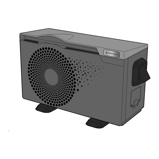
PENTAIR INVERTEMP® FL
INSTALLATION AND OPERATING MANUAL
IMPORTANT SAFETY INSTRUCTIONS,
PLEASE READ AND FOLLOW ALL THE INSTRUCTIONS,
KEEP THESE INSTRUCTIONS
PENTAIR AQUATIC SYSTEMS
(Rev. 12/2021)
Download the manual available in EN / FR / NL / DE / IT / ES / PO on www.pentairpooleurope.com
i =
IVTP-1M-FL
IVTP-2M-FL
IVTP-3M-FL
IVTP-4M-FL
IVTP-5M-FL
IVTP-6M-FL
IVTP-7M-FL
IVTP-8T-FL
EN
R32
Advertisement
Table of Contents

Related Manuals for Pentair INVERTEMP FL Series


Summary of Contents for Pentair INVERTEMP FL Series
- Page 1 PENTAIR INVERTEMP® FL IVTP-1M-FL IVTP-2M-FL IVTP-3M-FL IVTP-4M-FL IVTP-5M-FL IVTP-6M-FL IVTP-7M-FL IVTP-8T-FL INSTALLATION AND OPERATING MANUAL IMPORTANT SAFETY INSTRUCTIONS, PLEASE READ AND FOLLOW ALL THE INSTRUCTIONS, KEEP THESE INSTRUCTIONS PENTAIR AQUATIC SYSTEMS (Rev. 12/2021) Download the manual available in EN / FR / NL / DE / IT / ES / PO on www.pentairpooleurope.com...
- Page 2 Trade names and waivers: Pentair InverTemp® and Pentair® are trade names and/or registered trade names of Pentair and/or companies affiliated to Pentair. Unless otherwise stated, the names and brands of third parties used in the present document are not used to indicate any affiliation or endorsement between the owners of these trade names and Pentair. These names and brands can be registered trade names of said third parties or others.
- Page 3 WARNING AND IMPORTANT SAFETY INSTRUCTIONS This symbol indicates that the device uses R32, a This symbol indicates that a maintenance technician must handle this coolant featuring a low combustion speed. equipment according to the operating manual. This symbol indicates that the operating manual should be read attentively prior to use.
- Page 4 TABLE OF CHARACTERISTICS Modèle IVTP-1M-FL IVTP-2M-FL IVTP-3M-FL IVTP-4M-FL IVTP-5M-FL IVTP-6M-FL IVTP-7M-FL IVTP-8T-FL Model Conditions Dry air temperature: 28°C - Relative humidity: 80% - Input water temperature: 28°C Heating capacity 7,3 kW 9,3 kW 10,6 kW 13,1 kW 16,1 kW 20,4 kW 24,2 kW 27,8 kW (boost Mode)
-
Page 5: Delivery Transport
°C 10 bar = 1 MPa = 145 psi Control screen InverTemp™-FL 1M IVTP-1M-FL QC Passed MADE IN CHINA Pentair International Sarl S/N 1234ABCD1234ABCD1234ABCD01 Mfg Year Avenue de Sévelin 18 230V 50Hz~ / IPX4 / 2400 W SCAN CH-1004 Lausanne... - Page 6 INSTALLATION (SITE, TYPE OF SUPPORT, NECESSARY SPACE) – Install the HP outdoors at more than 2 metres from the pool, as per applicable laws (NF C 15 100). – Place the HP on the provided vibration absorbers on a surface that is stable, solid (able to bear the weight of the device) and level (prepare a concrete base if necessary).
-
Page 7: Hydraulic Connections
DIMENSIONS: Models IVTP-1M-FL IVTP-3M-FL 657 mm 977 mm 397 mm 510 mm 410 mm 103 mm 290 mm IVTP-2M-FL IVTP-4M-FL IVTP-5M-FL IVTP-6M-FL 756 mm 1076 mm 450 mm 669 mm 465 mm 92 mm 320 mm IVTP-7M-FL IVTP-8T-FL 922 mm 1175 mm 508 mm 669 mm... -
Page 8: Electrical Connections
ELECTRICAL CONNECTIONS: Connection of the power supply: – Prior to undertaking any intervention inside the HP, it is imperative to disconnect the power supply from the HP: there is a risk of electrocution that can cause damages, severe injuries, and even death. –... - Page 9 ELECTRICAL CONNECTIONS: Heating priority: The filtration pump can be connected to the HP to force the filtration to operate if the water is not at the desired temperature. Prior to this connection, a “dry contact” (normally open relay or connector) with a 230V AC coil should be provided. Electrical connections: –...
-
Page 10: General Use
SETTINGS: Water flow setting: – To optimise the heating performance and achieve power savings, the flow of water travelling through the HP should be adjusted. – The adjustment is done based on the reading of the adjustment pressure gauge. The adjustment is done by opening or closing the adjustment valve of the bypass. - Page 11 (water, gas...), the distance between the two must be greater than 20 cm. Electrical connections (power supply, remote control (RS-485) as an option) Note: your HP can be controlled through a dry contact (switch) or the Pentair RS-485 bus. 1: Remove the access hatch by unscrewing the two screws 2: Use the existing cable pullers to pull each cable of a suitable cross section (see the diagram below) into the free strain relief bushing (2.1 for the supply, 2.2 for the switch / RS-485).
- Page 12 Connection bus (remote ON-OFF) (Modbus card option) Pentair (IntelliPool, Speedeo...) Dry contact input (remote ON-OFF), remove the shunt that is present Pentair bus connection (IntelliPool, Speedeo ...) Connection to Maestro: Connection to IntelliPool: ON ? AUX1 CL 230 V ~...
- Page 13 REGULATION (ELECTRONIC CONTROL UNIT) P1-P2 relays for Selected mode Rotating fan 10:43 10:43 activated swimming pool 2020 pump 2021 2022 Date Water flow Compressor Year Month am/pm detected operating Time 10:43 10:43 Selected energy mode Timer 1 ON 9 45 Timer 1 OFF 18 00 Heating mode...
- Page 14 WiFi CONNECTION ≠1: Application download In the Apple or Android store, download the app Smart Life - Smart Living ≠2: Create an account and log in Follow the account creation instructions ≠3: Add the heat pump ≠3.1: Click “Add” ≠3.2: Select “Large device” ≠3.3: Select “Smart Heat Pump (BLE + WiFi)”...
-
Page 15: Operating Modes
OPERATING MODES - ECO-SILENCE heating or cooling mode: the most economical and silent. The HP varies the component speed to maintain an optimum sounds level and yield. Use of 30% to 60% of the power. The COP and sound level are prioritised, the fan works at min. speed and the compressor runs to optimise the COP. -
Page 16: Maintenance
MAINTENANCE – Prior to undertaking any maintenance operation on the HP, it is imperative to disconnect the power supply from the HP: there is a risk of electrocution that can cause damages, severe injuries, and even death. Maintenance operations are to be conducted by a qualified technician. Cleaning (must be conducted by a qualified technician at least once yearly): –... -
Page 17: Circuit Diagrams
CIRCUIT DIAGRAMS IVTP-1M-FL IVTP-2M-FL IVTP-3M-FL IVTP-4M-FL Reactor COMPRESSOR FAN MOTOR 220~240V 2N ~50Hz Towards the pump (≤1kW) Dry contact MODBUS ON/OFF Terminal strip 1 P1 P2 IN-IN Terminal strip 2 OUT1 BLUE YELLOW YELLOW PCB T8 PCB CN2 RED BLACK BROWN EGND AC-N AC-L... - Page 18 CIRCUIT DIAGRAMS IVTP-7M-LT IVTP-7M-FL Wired controller TO PCB CN1(A,B) COMPRESSOR CN485 Terminal strip 2 ON/OFF YEL GRN GND IN-IN IPM B IPM A BLACK HP: High pressure switch BROWN LP: Low pressure switch WP: Water pressure switch CN-L CN-N short-circuit BROWN ORANGE CN17...
- Page 19 RECYCLING THE HP When your HP reaches the end of its lifespan and you do not wish to keep it, do not throw it out with household waste. The HP must be brought to a selective recycling point for its reuse or recycling. It contains potentially hazardous substances that may harm the environment and that must, during recycling, be eliminated or neutralised.
- Page 20 Ave. de Sévelin 20, CH-1004 - LAUSANNE, Switzerland Copyright - Limited license: unless expressly authorised herein, no part of the content of the present document can be reproduced in any form or by any means without the prior written authorisation by Pentair International SRL.