Table of Contents
Advertisement
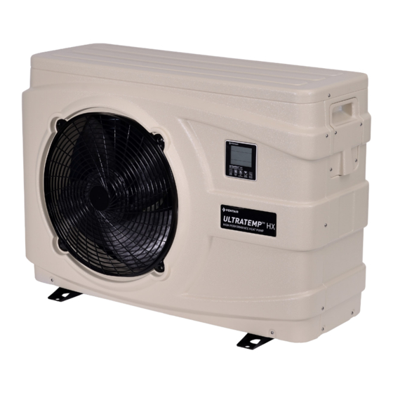
ULTRATEMP
HX
TM
HIGH PERFORMANCE HEAT PUMP
Should the installer or owner be unfamiliar with the correct installation or operation of
this type of equipment, you should contact the distributor/manufacturer for the correct
advice before proceeding with the installation or operation of this product.
The equipment operator or owner must be provided with this owner's manual.
Advertisement
Table of Contents
Troubleshooting

Related Manuals for Pentair eco select ULTRATEMP HX Series


Summary of Contents for Pentair eco select ULTRATEMP HX Series
- Page 1 ULTRATEMP HIGH PERFORMANCE HEAT PUMP Should the installer or owner be unfamiliar with the correct installation or operation of this type of equipment, you should contact the distributor/manufacturer for the correct advice before proceeding with the installation or operation of this product. The equipment operator or owner must be provided with this owner’s manual.
- Page 2 CUSTOMER SERVICE / TECHNICAL SUPPORT If you have questions about ordering Pentair Aquatic Systems, (“Pentair”) replacement parts, and pool products, please use the following contact information: Customer Service Australia Wide (8:30 A.M. to 5:00 P.M. AEST & AWST) Phone: 1300-137-344 e-mail: au.sales@pentair.com...
-
Page 3: Table Of Contents
Table of Contents Table of Contents Notices and Warnings ��������������������������������������������������������������������������������������������������������������������4 UltraTemp Contents and Overview ������������������������������������������������������������������������������������������������6 UltraTemp Heat Pump Kit Contents ........................... 6 ® UltraTemp Overview ................................6 ® Quick Start �������������������������������������������������������������������������������������������������������������������������������������7 Dimensions & Specifications ���������������������������������������������������������������������������������������������������������8 Dimensions ................................... 8 Specifications ..................................9 Installation ����������������������������������������������������������������������������������������������������������������������������������10 Location and Clearances .............................. -
Page 4: Notices And Warnings
Notices and Warnings Important Notice This manual provides installation and operation instructions for the product. Consult Pentair with any questions regarding this product. Attention Installer: This manual contains important information about the installation, operation and safe use of this product. Leave this manual with the owner and/or oper- ator of this product after installation. - Page 5 Notices and Warnings Notices and Warnings (Continued) The unit should be located on a solid, level, horizontal surface and securely WARNING fixed. Ensure free air-flow to all sides of the unit. Never use an extension cable to connect the unit to the electric power supply WARNING If there is no suitable earthed supply available, have one installed by a quali- fied electrician.
-
Page 6: Ultratemp Contents And Overview
Contents and Overview UltraTemp Contents and Overview UltraTemp Heat Pump Kit Contents ® • Heat Pump Unit. • Owners Manual. • Barrel unions x2 • Drain Hose x1. • Anti-vibration pads x4. UltraTemp Overview ® The swimming pool heat pump is one of the most economical ways of heating your swimming pool efficient- ly. -
Page 7: Quick Start
Quick Start Quick Start 1� Unlock Keypad - An icon will show on the screen indicating the keypad is locked. To 4� Turn on - Press for 1 second. The fan ON/OFF will start. A ‘Sun’ icon should show on the (UNLOCK) unlock: Press for 5 seconds, a ‘buzzer’... -
Page 8: Dimensions & Specifications
Dimensions & Specifications Dimensions Dimensions UltraTemp HX 9�5kW and 12kW UltraTemp HX 15kW, 17kW and units 21kW units 657mm 757mm 945mm 1125mm 159mm 181mm 620mm 750mm 366mm 446mm 417mm 490mm 96mm 86.5mm 370mm 455mm Page 8... -
Page 9: Specifications
Dimensions & Specifications Specifications Description UltraTemp UltraTemp 12kW UltraTemp 15kW 9�5kW Part No� UTHP-9-HX UTHP-12-HX UTHP-15-HX Ambient 24 Capacity (kW) 9.5 12.11 15.3 Water 26 C in 28 C out Power (kW) 1.53 1.98 2.47 6.20 6.12 6.20 Ambient 15 Capacity (kW) 8.24 9.25 12.1... -
Page 10: Installation
Installation Installation Only a qualified service person should install the UltraTemp Heat Pump. Before installing this product, refer to the Important Warning and Safety Instructions on page 4. Materials Needed for Installation The following items are needed and are to be supplied by the installer for all heat pump installa- tions: 1. -
Page 11: Location And Clearances
Electrical Installation Installation Location and Clearances All criteria given in the following sections reflect minimum clearances. However, each installation must also be evaluated, taking into account the prevailing local conditions such as proximity and height of walls, and proximity to public access areas. The UltraTemp® Heat Pump must be placed to provide clearances on all sides for maintenance and inspection. -
Page 12: Water Connections To The Heat Pump
Installation Anchor Clamp Installation (Continued) 4. Mark the position of the hole in each clamp on the equipment pad. 5. Use a masonry drill bit and drill a hole in the cement with a diameter as determined by the con- crete anchor, at each of the marks on the equipment pad. -
Page 13: Plumbing Connections
Note: Be advised that when pool equipment is located below the pool surface a leak can result in large-scale water loss or flooding. Pentair is not responsible for such water loss or flooding or damage. -
Page 14: Multiple Unit Installation
The Pentair heat pump may be used in conjunction with a gas or electric heater or any combination of heat sources including solar. All heat sources must be plumbed in series to work correctly and efficiently. -
Page 15: Electrical Connections
Installation Electrical Connections General Information Wiring connections must be made exactly as shown in the wiring diagram found on the inside of the heat pump access panel; see the wiring diagrams on pages 31-33. The UltraTemp Heat Pump must include a definite means of grounding and bonding. There is a ground lug inside the heat pump electrical compartment. - Page 16 Installation Electrical Connections (Continued) Figure 7: Location of Electrical Panel Optional Pump: P1 = 240V Active input (from supply) P2 = 240V Active output (to pump) Automation control input Connect Power Here L(Active), N(Neutral), and Earth Figure 8: Electrical Connections for Single Phase Units Page 16...
-
Page 17: Configuration
Configuration Configuration Control Panel ULTRATEMP HX HIGH PERFORMANCE HEAT PUMP TIMER MENU DOWN ON/OFF (CLOCK) (SET) (HEAT/COOL) (DEFROST) (UNLOCK) Figure 9: Control Panel Ref Icon Function Heat Mode This icon will show if the UltraTemp is on and is in Heating mode. The UltraTemp will heat the water until the set temperature is reached. -
Page 18: Control Panel (Continued)
Configuration Control Panel (Continued) Keypad Lock This icon will show if the keypad is locked. The keypad will auto- matically lock after a period of inactivity. To unlock, hold the power button for 5 seconds. Clock This shows the current time. To adjust the time, hold the TIMER button for 5 seconds. -
Page 19: Setting The Clock
Configuration Setting the Clock 1. On the main interface screen, press and hold for 5 seconds to enter into clock setting TIMER interface. (CLOCK) 2. The clock will begin flashing, press to modify the hours. The hours of the clock will start TIMER (CLOCK) flashing, press... -
Page 20: Menu / Setting Parameters
Configuration Menu / Setting Parameters 1. On main interface screen, press for 5 seconds to enter into parameter setting menu. MENU (SET) Press buttons to navigate to each parameter. Refer to table below for a list of DOWN all parameters. (HEAT/COOL) (DEFROST) 2. -
Page 21: Menu / Query Parameters
Configuration Menu / Query Parameters 1. On main interface screen, press to enter into parameter query menu. Press MENU (SET) (HEAT/COOL) buttons to navigate to each parameter. Refer to table below for a list of all parameters. DOWN (DEFROST) 2. Press at any time to confirm settings and go back to main interface. -
Page 22: Heating / Cooling Mode
Configuration Heating / Cooling Mode The UltraTemp heat pump can cool as well as heat the water. To switch from heating mode to cool- ing mode (and vice-versa): 1. On main interface screen, hold for five seconds. 2. The ‘sun’ icon will change to a ‘snow-flake’ icon, indicating that the UltraTemp is in cooling (HEAT/COOL) mode. -
Page 23: Connecting The Heat Pump To Automation
1. Run a two-conductor cable from the heat pump external control to the low voltage raceway to the motherboard in the Pentair Automation control centre. 2. Strip the conductors 7mm. Insert the wires into the GAS HEATER two-screw terminals (J19) on the motherboard. - Page 24 Automation Connection Connecting the Heat Pump to Automation (Continued) Connect 2-core 1mm2 cable to heat pump “REMOTE” terminals. AUTOMATION WIRING FOR HEAT PUMP ONLY Connect to Relay for Solar Pump (for seperate solar pump system) Solar To solar diverter Connect 2-core 1mm2 valve actuator cable to heat pump “REMOTE”...
-
Page 25: Maintenance & Troubleshooting
Owner Inspection Pentair recommends that you inspect your heat pump on a continual basis and especially after abnormal weather conditions. The following basic guidelines are suggested for your inspection: 1. Make sure the front of the unit is accessible for future service. -
Page 26: Professional Maintenance And Service
Maintenance & Troubleshooting Maintenance & Troubleshooting Continued The UltraTemp® Heat Pump will produce condensation (water) while in operation. The heat pump base is designed to allow the condensation to exit through the bottom drain port when the unit is running. The condensation will increase as the outdoor air humidity level increases. Check the following at regular intervals to ensure proper condensate drainage: 1. - Page 27 Maintenance & Troubleshooting Maintenance & Troubleshooting Continued 3. Turn on the filter pump to supply water to the heat pump. Open the filter air bleeder and circu- late water through the system long enough to bleed all the air out of the pool system. Check for leaks in and around the heat pump.
-
Page 28: Troubleshooting
Please check whether: • The clock and the day of the week are set correctly, adjust if necessary. If you cannot correct the fault yourself, please contact Pentair for after-sales service. System Protections / Error Codes When an error occurs or the protection mode is set automatically,the wired controller will display an error code as below. - Page 29 Maintenance & Troubleshooting Code Failure Possible reasons Remedy Er03 Water flow switch failure 1) Inadequate water flow 1) Check the pump 2) Water flow switch dam- 2) Replace the water flow aged switch 3) Main PCB damaged 3) Replace the PCB Er04 Anti-freeze protection in This function occurs when...
-
Page 30: System Protections / Error Codes (Continued)
Maintenance & Troubleshooting System Protections / Error Codes (Continued) Code Failure Possible reasons Remedy Er21 Ambient temp sensor fail- 1) Sensor open circuit 1) Check the sensor con- 2) Sensor short circuit nection 3) Main PCB damaged 2) Replace the sensor 3) Replace the main PCB Er23 Low outlet water temp pro-... -
Page 31: Replacement Parts
Appendix Replacement Parts ULTRATEMP HX HEAT PUMP ® Part Part Item Description Item Description No� No� ULTRATEMP HX REPLACEMENT PARTS 803153 GRILL (15kW, 17kW & 21kW) 803115 FRONT PANEL (9kw & 12kW) 803100 TOP COVER (9kw & 12kW) 801328 FRONT PANEL (15kW, 17kW & 21kW) 801326 TOP COVER (15kW, 17kW &... -
Page 32: Wiring Diagrams
Appendix Wiring Diagrams Wiring Diagram: UltraTemp 9.5kW, 12kW & 15kW models Page 32... - Page 33 Appendix Wiring Diagrams Continued Wiring Diagram: UltraTemp 17kW & 21kW models Page 33...
-
Page 34: Environmental Information
Environmental Information Environmental Information This equipment contains fluorinated greenhouse gases covered by the Kyoto Protocol. It should only be serviced or dismantled by professional trained engineers. This equipment contains R410A refrigerant in the amount as stated in the specification. Do not vent R410A into the atmosphere: R410A, is a fluorinated greenhouse gas with a Global Warming Potential (GWP) = 1975. - Page 35 Notes Page 35...
- Page 36 +61 3 9709 5800 Fax: +61 3 9709 5888 © 2017 Information contained here-in remains the property of Pentair Australia Pty. Ltd. Any reproduction, display, publication, modification or distribution is strictly prohibited without the prior written permission of Pentair Australia Pty. Ltd.