
Related Manuals for Nvidia TQ8 00 Series


Summary of Contents for Nvidia TQ8 00 Series
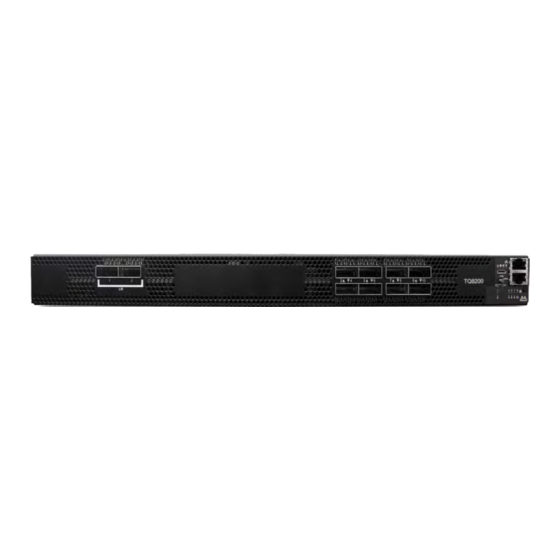
- Page 1 TQ8x00 MetroX®-2 HDR 200Gb/s InfiniBand Switch Systems User Manual Exported on Nov/02/2023 01:41 PM...
-
Page 2: Table Of Contents
Table of Contents Introduction..................6 Speed and Switching Capabilities ..............6 Features ....................7 Certifications ..................7 Installation ..................8 System Installation and Initialization .............8 Safety Warnings ..................8 Air Flow....................8 Package Contents ..................9 19” System Mounting Options ..............10 Fixed Rail Kit ..................10 Removing the System from the Rack............ - Page 3 I²C ....................29 Reset Button ..................30 LEDs ....................30 LED Notifications................... 30 System Status LED ................31 Fan Status LED.................. 31 Power Supply Status LEDs..............32 Unit Identification LED................ 33 Port LEDs ..................34 Inventory Pull-out Tab................35 Troubleshooting ................36 Specifications..................37 Appendix ..................38 Accessory and Replacement Parts ...............
- Page 4 Relevant for Models: MTQ8100 and MTQ8200 This manual describes the installation and basic use of the NVIDIA 1U HDR InfiniBand switch systems based on the NVIDIA Quantum™ switch ASIC. This manual is intended for IT managers and system administrators. Ordering Information Syste NVIDIA Legacy OPN...
- Page 5 This document contains information regarding the configuration and management of the MLNX-OS® software. See https://docs.nvidia.com/ networking/category/mlnxos. Hands-on workshops https://academy.nvidia.com/en/infiniband-customized-training/ NVIDIA Networking Support See https://www.nvidia.com/en-us/networking/support/. Revision History A list of the changes made to this document are provided in Document Revision History.
-
Page 6: Introduction
40 kilometers. NVIDIA TQ8100-HS2F supports up to 2 EDR QSFP28 MetroX-2 ports running 100Gb/s for up to 10 km, and up to 8 standard HDR local ports running 200Gb/s. NVIDIA Quantum MetroX-2 TQ8200-HS2F supports up to 2 EDR QSFP28 MetroX-2 ports running 100Gb/s for up to 40 km, and up to 8 standard HDR local ports running 200Gb/s. -
Page 7: Features
In the main menu, click on Products > InfiniBand/VPI Switch Systems, and select the desired product page. Certifications The list of certifications (such as EMC, Safety and others) per system for different regions of the world is located on the NVIDIA website at http://www.mellanox.com/page/ environmental_compliance. -
Page 8: Installation
• Unless otherwise specified, NVIDIA products are designed to work in an environmentally controlled data center with low levels of gaseous and dust (particulate) contamination. •... -
Page 9: Package Contents
• Connector (front) side inlet to power side outlet - marked with red power supplies/ fans FRUs’ handles. Air Flow Direction Marking - Connector Side Inlet to Power Side Outlet Certain systems are offered with one airflow pattern only (P2C/C2P). To view the airflow patterns offer, please refer to the Ordering Information. -
Page 10: 19" System Mounting Options
• 1 – Quick Start Guide If anything is damaged or missing, contact your sales representative at Networking- support@nvidia.com. 19” System Mounting Options By default, the systems are shipped with the static rail kit described in Fixed Rail Kit. Fixed Rail Kit ... - Page 11 Prerequisites: Before mounting the system to the rack, select the way you wish to place the system. Pay attention to the airflow within the rack cooling, connector and cabling options. While planning how to place the system, consider the two installation options shown in the figures below, and review the following points: •...
- Page 12 Standard Racks (580-800 mm) Installation Options Front Side Rear Side In short racks, the system’s ventilation openings should be framed by the designated windows in the rails, as shown below. To mount the system into the rack: At least two people are required to safely mount the system in the rack. ...
- Page 13 Attaching the Rails to the Chassis Attach the left and right rack mount brackets (C) to the switch, by gently pushing the switch chassis’ pins through the slider key holes, until locking occurs. Secure the system in the brackets by screwing the remaining 2 flat head Phillips screws (F) in the designated points with a torque of 1.5±0.2 Nm. ...
- Page 14 While each rack U (unit) consists of three holes, the cage nut should be installed vertically with its ears engaging the top and bottom holes only. While your installation partner is supporting the system’s weight, perform the following steps: Attach the two rack mount blades (B) to the back side (FRU side) of the rack by inserting four M6 screws (E) in the designated cage nuts.
-
Page 15: Removing The System From The Rack
To remove a cable, disengage the locks and slowly pull the connector away from the port receptacle. The LED indicator for that port will turn off when the cable is unseated. For full cabling guidelines, ask your NVIDIA representative for a copy of NVIDIA Cable Management Guidelines and FAQs Application Note. -
Page 16: Splitter (Breakout) Cables And Adapters
For more information about port LEDs, refer to Port LEDs. Do not force the cable into the cage with more than 40 newtons / 9.0 pounds / 4kg force. Greater insertion force may cause damage to the cable or to the cage. Cable Orientation Splitter (Breakout) Cables and Adapters ... - Page 17 • In order to be able to use this feature, the system profile command must be activated with split-ready configuration (cross-reference to system profile command). For more information on how to change the system’s profile to allow Split-Ready configuration, how to change the module type to a split mode, and how to unsplit a split port, please refer to the "InfiniBand Switching"...
-
Page 18: Initial Power On
It may take up to five minutes to turn on the system. If the System Status LED shows amber after five minutes, unplug the system and call your NVIDIA representative for assistance. Check the System Status LEDs and confirm that all of the LEDs show status lights consistent with normal operation (initially flashing, and then moving to a steady color) as shown below. -
Page 19: System Bring-Up Of Managed Systems
The bring-up procedures described in this section do not apply to unmanaged/externally managed systems. Such systems are ready for operation after power-on. In order to query the system, perform firmware upgrade or other firmware operation. Refer to the latest NVIDIA Firmware tools (MFT) located on the NVIDIA web site (https://network.nvidia.com/ products/adapter-software/firmware-tools/). - Page 20 Configuration Wizard Session table below. Configuration Wizard Session Comments Wizard Session Display NVIDIA configuration wizard You must perform this configuration the first time you Do you want to use the wizard for initial operate the system or after resetting the system. Type configuration? yes ‘y’...
- Page 21 “configuration jump-start” in Config mode. The table below shows an example of static IP configuration for mgmt0 interface. Configuration Wizard Session - Static IP Configuration NVIDIA configuration wizard Do you want to use the wizard for initial configuration? yes ...
-
Page 22: Remote Connection
(config) # Step 6. Check the software version embedded in your system, using the command ‘show version’. Compare this version to the latest version that can be retrieved from NVIDIA support site. To upgrade software, please refer to the MLNX-OS User Manual. -
Page 23: Fans
Make sure that the power supply unit that you are NOT replacing is showing all green, for both the power supply unit and System Status LEDs. Power supply units have directional air flows similar to the fan module. The fan module airflow must coincide with the airflow of all of the power supply units. - Page 24 Make sure that the fans have the air flow that matches the model number. An air flow opposite to the system design will cause the system to operate at a higher (less than optimal) temperature. For power supply unit air flow direction, refer to Flow.
-
Page 25: Software Management
Software and firmware updates are available from the NVIDIA Support website. Check that your current revision is the same one that is on the NVIDIA website. If not upgrade your software. Copy the update to a known location on a remote server within the user’s LAN. -
Page 26: Updating Firmware On Externally Managed Systems
Firmware updates should normally be conducted in-band. The use of the MTUSB-1 device is intended for cases of debug or firmware corruption and should be conducted by NVIDIA FAEs or Support engineers, or by trained users at the customer's site. - Page 27 4. If the current version is not the latest version, follow the directions in the MFT User manual to burn the new firmware inband. For further information, please refer to MFT User Manual at https://docs.nvidia.com/networking/ category/mft.
-
Page 28: Interfaces
QSFP56 port can be connected with QSFP56 cable or connector for 40/56/100/200Gb/s. The system offers High Power class 4 transceivers support in all ports. You may use the following NVIDIA transceivers, designed for InfiniBand EDR links on up to 10km and 40km of single mode fiber:... -
Page 29: Rs232 (Console)
RS232 (Console) The RS232 serial “Console” port is labeled The port labeled “Console” is an RS232 serial port on the front side of the chassis that is used for initial configuration and debugging. Upon first installation of the system, you need to connect a PC to this interface and configure network parameters for remote connections. -
Page 30: Reset Button
• This interface is not found in externally managed systems. • The I²C interface is used for debugging and is intended for NVIDIA debug personnel only. Reset Button The reset button is located on the front side of the system under the RJ45 connector. This reset button requires a tool to be pressed. -
Page 31: System Status Led
The LED in the red oval shows the system’s status. It may take up to five minutes to turn on the system. If the System Status LED shows red after five minutes, unplug the system and call your NVIDIA representative for assistance. System Status LED Assignments LED Behavior... -
Page 32: Power Supply Status Leds
LED Behavior Description Action Required Solid Green All fans are up and running. Solid Amber Error, one or more fans are not operating The faulty FRUs should be replaced. properly. System boot Fan Status Rear LED Assignments (One LED per Fan) LED Behavior Description Action Required... -
Page 33: Unit Identification Led
Action Required Solid Green The PSU is running normally. Flashing Green 1Hz AC present / Only 12VSB on (PSU off) or PSU Call your NVIDIA representative for in Smart-on state. assistance. Amber AC cord unplugged or AC power lost while... -
Page 34: Port Leds
Port LEDs By utilizing two pairs of two lanes per port, the systems can support up to 16 ports of 100G. You may switch between the two following states by pressing on the LED Splitting Control button: • Displaying the link status of a single 4-lane port, or of the lower 2-lane split port (if a splitter cable is used). -
Page 35: Inventory Pull-Out Tab
logical connection is made the LED will change to green. When data is being transferred the light will blink green. Inventory Pull-out Tab This document is preliminary and subject to change. The system’s inventory parameters (such as serial number, part number and GUID address) can be extracted from the inventory pull-out tab on the lower right side of the front panel. -
Page 36: Troubleshooting
Troubleshooting This document is preliminary and subject to change. Problem Symptoms Cause and Solution Indicator LEDs System Status LED is blinking Cause: MLNX-OS software did not boot properly and only firmware for more than 5 minutes is running. Solution: Connect to the system via the console port, and check the software status. -
Page 37: Specifications
Global Power Consumption: Global Power Consumption • Max power consumption with all ports connected to AOCs: 600W • Max power consumption with all ports connected to DACs: 538W Main Devices CPU: x86 ComEx Broadwell D-1508 Switch: NVIDIA Quantum™ Throughput Switching: 4Tb/s... -
Page 38: Appendix
200G 1U systems 1100W AC Power Supply w/ C2P airflow HAR000631 Harness RS232 2M cable – DB9 to RJ-45 (for managed switches only) ACC000501 NVIDIA 1U switch black power cord, 250V, 10A, 1830MM and C14 TO C13. Note: Can be purchased as a stand-alone product with PN ACC000501-BUY. -
Page 39: Interface Specifications
• Emergency – 130°C: In case the firmware fails to shut down the ASIC device upon crossing its Critical threshold, the device will auto-shutdown upon crossing the Emergency (130°C) threshold. Interface Specifications This document is preliminary and subject to change. QSFP Pin Description QSFP Pin Description Connector Pin Number... - Page 40 Connector Pin Number Pin Name Signal Description Vcc Rx +3.3 V Power supply receiver 2-wire serial interface clock 2-wire serial interface data Ground Rx3p Receiver Non-Inverted Data Output Rx3n Receiver Inverted Data Output Ground Rx1p Receiver Non-Inverted Data Output Rx1n Receiver Inverted Data Output Ground Ground...
-
Page 41: Rj45 To Db9 Harness Pinout
RJ45 to DB9 Harness Pinout In order to connect a host PC to the Console RJ45 port of the system, a RS232 harness cable (DB9 to RJ45) is supplied. RJ45 to DB9 Harness Pinout Disassembly and Disposal This document is preliminary and subject to change. -
Page 42: Disassembly Procedure
Disassembly Procedure To disassemble the system from the rack: Unplug and remove all connectors. Unplug all power cords. Remove the ground wire. Unscrew the center bolts from the side of the system with the bracket. Support the weight of the system when you remove the screws so that the system does not fall. -
Page 43: Document Revision History
Document Revision History Date Revision Description August 2022 Updated OPNs in: • Ordering Information • Installation • Accessory and Replacement Parts August 2021 Updated Software Management. August 2020 Initial release... - Page 44 NVIDIA accepts no liability related to any default, damage, costs, or problem which may be based on or attributable to: (i) the use of the NVIDIA product in any manner that is contrary to this document or (ii) customer product designs.
- Page 45 Copyright © 2023 NVIDIA Corporation & affiliates. All Rights Reserved.