
Related Manuals for Nvidia Mellanox SB7700


Summary of Contents for Nvidia Mellanox SB7700
- Page 1 1U EDR 100Gb/s InfiniBand Switch Systems and IB Router Hardware User Manual SB7700, SB7790, SB7800, SB7890, SB7780 Exported on Oct/14/2021 10:05 AM...
-
Page 2: Table Of Contents
Table of Contents Introduction..................7 Speed and Switching Capabilities ..............8 Management Interfaces and FRUs ..............8 Features ....................8 Certifications ..................9 Installation ..................10 System Installation and Initialization ............10 Safety Warnings ..................10 Air Flow....................13 Package Contents .................. 14 19" Rack Mounting Options ............... 15 Static Rail Kit .................. - Page 3 Management ..................33 USB ....................33 Reset Button ..................33 LEDs ....................34 LED Notifications................... 34 System Status LED ................34 Fan Status LED.................. 35 Power Supply Status LEDs..............36 Unit Identification LED................ 37 Bad Port LED ..................38 Port LEDs ..................38 Inventory Pull-out Tab................
- Page 4 Sigurnosna upozorenja za instaliranje (Croatian)......... 76 Avvertenze di sicurezza per l’installazione (Italian) ........79 Montaj Güvenlik Uyarıları (Turkish) ............82 Japan VCCI Statement ................ 84 (Hebrew) 48 ............הוראות בטיחות בהתקנה Document Revision History ..............88...
- Page 5 Relevant for Models: SB7700, SB7790, SB7800, SB7890, SB7780 and SB7880. About this Manual This manual describes the installation and basic use of the NVIDIA InfiniBand EDR 1U switches. Ordering Information The following table lists ordering information for the available systems.
- Page 6 Document Description InfiniBand Architecture The InfiniBand Architecture Specification provided by IBTA. Specification Volume 1, Release 1.2.1, and Volume 2, Release 1.3 MLNX-OS® User Manual This document contains information regarding the configuration and management of the MLNX-OS® software. See http://www.mellanox.com/page/ mlnx_ox. Hands-on workshops https://academy.mellanox.com/en/infiniband-customized-training/ On-site/remote services...
-
Page 7: Introduction
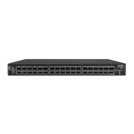
Introduction Mellanox SB77X0/SB78X0 switch systems provide the highest performing fabric solution in a 1U form factor by delivering up to 7.2Tb/s of non-blocking bandwidth with sub 90ns port-to-port latency. These systems are the industry's most cost-effective building blocks for embedded systems and storage with a need for low port density systems. -
Page 8: Speed And Switching Capabilities
SB7790/SB7890 Rear Side View *The SB7800 models include one MGT port labeled Speed and Switching Capabilities The table below describes maximum throughput and interface speed per system model. System Model EDR 100Gb/s QSFP28 Interfaces Max Throughput SB7700 7.2Tb/s SB7790 7.2Tb/s SB7800 7.2Tb/s SB7890 7.2Tb/s... -
Page 9: Certifications
Certifications The list of certifications (such as EMC, Safety and others) per system for different regions of the world is located on the Mellanox website at http://www.mellanox.com/page/ environmental_compliance. -
Page 10: Installation
Unless otherwise specified, NVIDIA products are designed to work in an environmentally controlled data center with low levels of gaseous and dust (particulate) contamination. The operation environment should meet severity level G1 as per ISA 71.04 for gaseous contamination and ISO 14644-1 class 8 for cleanliness level. - Page 11 Safety Warning (English) Installation Instructions Read all installation instructions before connecting the equipment to the power source. Bodily Injury Due to Weight Use enough people to safely lift this product. Heavy Equipment This equipment is heavy and should be moved using a mechanical lift to avoid injuries. Risk of Electric Shock! •...
- Page 12 This system has double pole/neutral fusing. Remove all power cords before opening the cover of this product or touching any internal parts. Multiple Power Inlets Risk of electric shock and energy hazard. The PSUs are all independent. Disconnect all power supplies to ensure a powered down state inside of the switch platform. During Lightning—Electrical Hazard During periods of lightning activity, do not work on the equipment or connect or disconnect cables.
-
Page 13: Air Flow
This unit is intended for connection to a TN power system and an IT power system of Norway only. Air Flow NVIDIA systems are offered with two air flow patterns: • Power (rear) side inlet to connector side outlet - marked with blue power supplies/fans FRUs’... -
Page 14: Package Contents
• Connector (front) side inlet to power side outlet - marked with red power supplies/fans FRUs’ handles. Air Flow Direction Marking - Connector Side Inlet to Power Side Outlet All servers and systems in the same rack should be planned with the same airflow direction. All FRU components need to have the same air flow direction. -
Page 15: 19" Rack Mounting Options
If anything is damaged or missing, contact your sales representative at Networking- support@nvidia.com. 19" Rack Mounting Options • By default, the system is sold with the static rail kit described in Static Rail Kit. • A telescopic rail-kit can be purchased separately. For the telescopic rail kit installation... - Page 16 Before mounting the system to the rack, select the way you wish to place the system. Pay attention to the airflow within the rack cooling, connector and cabling options. While planning how to place the system, consider the two installation options shown in the figure below, and review the following points: •...
- Page 17 Attaching the Rails to the Chassis Attach the left and right rack mount brackets (B) to the switch, by gently pushing the switch chassis’ pins through the slider key holes, until locking occurs. Secure the system in the brackets by screwing the remaining 2 flat head Phillips screws (E) in the designated points with a torque of 1.5±0.2 Nm. ...
-
Page 18: Removing The System From The Rack
Mount the system into the rack enclosure, and attach the brackets installed on the system to the rack’s posts. Secure the brackets to the rack’s posts by inserting four M6 screws in the designated cage nuts, as described in the figure below. Do not tighten the screws yet. Attaching the Brackets to the Rack Slide the two blades into the left and right rails, and adjust them to fit your rack's depth. - Page 19 Kit OPN Rack Size and Rack Depth Range MTEF-KIT-B Short: 17"-24" MTEF-KIT-S Standard (long): 24"-38" The following parts are included in the rail kit package (see figure below): • 1x Right inner rail (A) • 1x Left inner rail (B) •...
- Page 20 Before mounting the system to the rack, select the way you wish to place the system. Pay attention to the airflow within the rack cooling, connector and cabling options. While planning how to place the system, review the following points: •...
-
Page 21: Removing The System From The Rack
Attaching the Inner Rails Secure the chassis in the inner rails by screwing the 2 flat head Phillips screws (F) in the designated points with a torque of 1.5±0.2 Nm. Securing the Chassis in the Inner Rails Slide the switch into the rack by carefully pushing the inner rails into the outer rails installed on the rack. ... -
Page 22: Cable Installation
Pull the unit out until braking is felt. For safety purposes, the locking mechanism will not allow a complete removal of the unit at this stage. Pulling the Unit Outwards Press on the locking spring (appears in red in the figure below) on both sides simultaneously, and continue pulling the unit towards you until it is fully removed. ... -
Page 23: Initial Power On
It may take up to five minutes to turn on the system. If the System Status LED shows red after five minutes, unplug the system and call your NVIDIA representative for assistance. Check the System Status LEDs and confirm that all of the LEDs show status lights consistent with normal operation (initially flashing, and then moving to a steady color) as shown in figures below. -
Page 24: System Bring-Up Of Managed Systems
The bring-up procedures described in this section do not apply to unmanaged/externally managed systems. Such systems are ready for operation after power-on. In order to query the system, perform firmware upgrade or other firmware operation. Refer to the latest NVIDIA Firmware tools (MFT) located at www.mellanox.com > Products > Software > Firmware tools. - Page 25 <localhost># ssh admin@<ip-address> Mellanox MLNX-OS Switch Management Password: Mellanox Switch Mellanox configuration wizard Do you want to use the wizard for initial configuration? yes Step 1: Hostname? [my-switch] Step 2: Use DHCP on mgmt0 interface? [yes] no <localhost># Manual Host Configuration To perform initial configuration of the system: Step 1.
- Page 26 “configuration jump-start” in Config mode. The table below shows an example of static IP configuration for mgmt0 interface. Configuration Wizard Session - Static IP Configuration NVIDIA configuration wizard Do you want to use the wizard for initial configuration? yes ...
-
Page 27: Remote Connection
(config) # Step 6. Check the software version embedded in your system, using the command ‘show version’. Compare this version to the latest version that can be retrieved from NVIDIA support site. To upgrade software, please refer to the MLNX-OS User Manual. -
Page 28: Fans
Make sure that the power supply unit that you are NOT replacing is showing all green, for both the power supply unit and System Status LEDs. Power supply units have directional air flows similar to the fan module. The fan module airflow must coincide with the airflow of all of the power supply units. - Page 29 Make sure that the fans have the air flow that matches the model number. An air flow opposite to the system design will cause the system to operate at a higher (less than optimal) temperature. For power supply unit air flow direction, refer to Flow.
-
Page 30: Software Management
Software and firmware updates are available from the NVIDIA Support website. Check that your current revision is the same one that is on the NVIDIA website. If not upgrade your software. Copy the update to a known location on a remote server within the user’s LAN. -
Page 31: Updating Firmware On Externally Managed Systems
• (Non-typical) Via the I²C port of the switch using a NVIDIA MTUSB-1 device connecting to a server's USB port on the one end and to the I²C port of the switch on the other. Firmware updates should normally be conducted in-band. The use of the MTUSB-1 device is intended for cases of debug or firmware corruption and should be conducted by NVIDIA Fields or Support engineers, or by trained users at the customer's site. -
Page 32: Interfaces
Each QSFP28 port can be connected with QSFP28 cable or connector for 40/56/100 Gb/s. The system offers High Power class 4 transceivers support in all ports. Speed InfiniBand speed is auto-adjusted by the infiniBand protocol. NVIDIA systems support QDR/FDR10/ FDR/EDR InfiniBand. •... -
Page 33: Management
Only original NVIDIA cables supplied with the switch package can be used to connect a switch system to the server. Connecting any cable other than the NVIDIA supplied console cable may cause an I²C hang. Using uncertified cables may damage the I²C interface. -
Page 34: Leds
LEDs See LED Notifications. LED Notifications The system’s LEDs are an important tool for hardware event notification and troubleshooting. LEDs Symbols Symbol Name Description Normal Conditions System Status LED Shows the health of the system. Green/Flashing green when booting Fan Status LED Shows the health of the fans. -
Page 35: Fan Status Led
Both of the System Status LEDs (front and back) supply identical information. It may take up to five minutes to turn on the system. If the System Status LED shows red after five minutes, unplug the system and call your NVIDIA representative for assistance. System Status LED Assignments LED Behavior Description... -
Page 36: Power Supply Status Leds
Fan Status Rear LED Assignments (One LED per Fan) LED Behavior Description Action Required Solid Green A specific fan unit is operating. Solid Amber* A specific fan unit is missing or not The fan unit should be replaced. operating properly. System boot * A limited number of MSB7800-ES2F system units may show Solid Red instead of Solid Amber. -
Page 37: Unit Identification Led
Action Required Solid Green The PSU is running normally. Flashing Green 1Hz AC present / Only 12VSB on (PSU off) or PSU Call your NVIDIA representative for in Smart-on state. assistance. Amber AC cord unplugged or AC power lost while... -
Page 38: Bad Port Led
Bad Port LED The Bad Port LED indicator is used to indicate symbol errors in one or more system ports. Bad Port LED Assignments LED Behavior Description Action Required No symbol errors have been received in last few seconds (normal condition). Flashing Amber Error, one or more ports have received Check symbol error counters on the... -
Page 39: Inventory Pull-Out Tab
Inventory Pull-out Tab The system’s inventory parameters (such as serial number, part number and GUID address) can be extracted from the inventory pull-out tab on the lower right side of the front panel. Pull-out Tab... -
Page 40: Troubleshooting
Troubleshooting Problem Symptoms Cause and Solution Indicato LEDs System Status LED is blinking Cause: MLNX-OS software did not boot properly and only firmware for more than 5 minutes is running. Solution: Connect to the system via the console port, and check the software status. - Page 41 Problem Symptoms Cause and Solution Indicato System The date and time settings Cause: date and were reset to the default Date and time are reconfigured by the operating system. time configuration following an AC reset power loss Solution: • To set the system’s date and time manually, run: # clock set <hh:mm:ss>...
-
Page 42: Specifications
Max power with optical cables (assuming 3.5W per port): 332W Main Devices CPU: ICPU (in SB7700/SB7800/SB7780 only): Intel Celeron Dual Core 1047UE (x86) Switch IC: SB7700, SB7790, SB7780: NVIDIA Switch-IB™ SB7800, SB7890: NVIDIA Switch-IB™ 2 PCIe (in SB7700/SB7800/ 4XPCIe Gen2.0 SB7780 only) Memory 4GB RAM DDR3 16GB SSD... - Page 43 Feature Value Throughput 7.2Tb/s...
-
Page 44: Appendixes
460W AC Power Supply w/ C2P air flow (rear to front) HAR000028 Harness RS232 2M cable – DB9 to RJ-45 (for managed switches only) ACC000501 NVIDIA® 1U switch black power cord, 250V, 10A, 1830MM and C14 TO MTEF-FANF-A Fan module w/rear to front airflow fan for SB77X0 switch systems MTEF-FANR-A... -
Page 45: Interface Specifications
Interface Specifications QSFP28 Pin Description QSFP Pin Description Connector Pin Number Pin Name Signal Description Ground Tx2n Transmitter Inverted Data Input Tx2p Transmitter Non-Inverted Data Input Ground Tx4n Transmitter Inverted Data Input Tx4p Transmitter Non-Inverted Data Input Ground Mod-SelL Module Select ResetL Module Reset Vcc Rx... - Page 46 Connector Pin Number Pin Name Signal Description Rx3p Receiver Non-Inverted Data Output Rx3n Receiver Inverted Data Output Ground Rx1p Receiver Non-Inverted Data Output Rx1n Receiver Inverted Data Output Ground Ground Rx2n Receiver Inverted Data Output 3 Rx2p Receiver Non-Inverted Data Output 3 Ground Rx4n Receiver Inverted Data Output 4...
-
Page 47: Rj-45 Console And I²C Interface
RJ-45 CONSOLE and I²C Interface RJ-45 Console and I²C interfaces are integrated in the same connector. Due to that, connecting any cable other than the Mellanox supplied console cable may cause an I²C hang. Using uncertified cables may damage the I²C interface. Refer to the Replacement Parts Ordering Numbers appendix for harness details. -
Page 48: Disassembly And Disposal
Disassembly and Disposal Disassembly Procedure To disassemble the system from the rack: Unplug and remove all connectors. Unplug all power cords. Remove the ground wire. Unscrew the center bolts from the side of the system with the bracket. Support the weight of the system when you remove the screws so that the system does not fall. -
Page 49: Switch Safety Warnings (Multiple Languages)
Switch Safety Warnings (Multiple Languages) Safety warnings are provided in multiple languages for your convenience: • Switch Safety Warnings (English) • Nordic Countries Notices 安裝安全性警告 (Simplified Chinese) • • China CCC Warning Statement • Taiwan RoHS Declaration • Taiwan BSMI Class A Statement - Warning to the User! 安裝安全性警告... - Page 50 • With the fan module removed power pins are accessible within the module cavity. Do not insert tools or body parts into the fan module cavity. • For AC powered switch systems: Disconnecting one power supply only disconnects one module. To isolate the unit completely, all connected power supplies must be disconnected. Over-temperature This equipment should not be operated in an area with an ambient temperature exceeding the maximum recommended: 45°C (113°F).
- Page 51 When this product is mounted or serviced in a rack, special precautions must be taken to ensure that the system remains stable. In general, the rack should be filled with equipment starting from the bottom to the top. Equipment Installation This equipment should be installed, replaced, and/or serviced only by trained and qualified personnel.
-
Page 52: Nordic Countries Notices
A readily accessible Listed branch circuit overcurrent protective device rated 20 A must be incorporated in the building wiring. Do Not Use the Switch as a Shelf or Work Space Caution: Slide/rail mounted equipment is not to be used as a shelf or a work space. The rails are not intended for sliding the unit away from the rack. - Page 53 重設備 本設備極重,應使用機械式起重機來搬移,以避免人員受傷。 有觸電的危險 有觸電的危險!拆除風扇模組後,即可接觸到模組空腔內的電源針腳。請勿將工具或機身零件插入 到風扇模組空腔內。 溫度過高 本設備不應在超過所建議的最高環境溫度的區域中運作:45°C (113°F)。此外,為了保證氣流的流 通正常,請在通風口旁保留至少 8 公分 (3 英吋) 的間距。 堆疊機箱 機箱不應堆疊在任何其他設備上。如果機箱掉落,可能造成人員受傷與設備損壞。 複式電源連接時的電擊危險 本設備附有備援電源供應器或在適當位置配有空白蓋板。如果是電源供應器空白蓋板,在空白蓋板 已取下或未牢牢固訂的情況下,請勿操作本產品。 雙極/中性保險絲 本系統具有雙極/中性保險絲。請拔掉所有電源線後,再打開本產品的蓋板或碰觸任何內部零件。 多電源輸入座 電擊與能源危害的危險。所有 PSU 均各自獨立。將所有電源供應器斷電,確保交換器平台內部在 電源關閉狀態。 閃電時的電擊危險 在閃電期間,不要使用本設備或連接或拔下纜線。 機架安裝與維修 此產品已安裝在機架中或在機架中維修時,必須採取特定預防措施以確保系統維持穩定。一般您應 該將設備從底部到頂端放滿機架。 設備安裝 本設備僅限由經過訓練與/或合格的人員安裝、更換或維修。 設備棄置 棄置本設備應遵照所有國內法規。 當地與國家電氣法規...
- Page 54 請遵照當地與國家電氣法規安裝本設備。 安裝法規 請務必遵循最新版的國家電氣法規,安裝本設備。在北美地區,請務必遵循美國國家電工法規和加 拿大電工法規中的適用規定,安裝本設備。 更換電池 警告:只能以 UL 認可電池,且取得最大異常充電電流低於 4mA 認證的電池進行更換。 若更換錯誤類型的電池,會有爆炸的危險。 請依據指示棄置廢電池。 UL 列名和 CSA 認證電源線 北美地區在接上電源時,請選用獲得 UL 列名和 CSA 認證、三個導體、[16 AWG] 附成型插頭,額 定值為 125 V、[13 A],長度至少 1.5 公尺 [六英尺],但不超過 4.5 公尺的電源線。 歐洲地區在接上電源時,請選用國際協調式且標示有 <HAR> 字樣、三個導體、標稱截面至少 1.0 平方公厘,額定值為 300 V,採用 PVC 絕緣的電源線。電源線需有成型插頭,額定值為 250 V, 10 A。...
- Page 55 本设备仅限连接至挪威的 TN 电源系统和 IT 电源系统。 China CCC Warning Statement...
-
Page 56: 安裝安全性警告 (Chinese)
Taiwan RoHS Declaration Taiwan BSMI Class A Statement - Warning to the User! 安裝安全性警告 (Chinese) 安装指示 本设备附有备援电源供应器或在适当位置配有空白盖板。 因重量导致的人身受伤... - Page 57 为了安全起见,请安排足够的人员以合力抬起本产品。 重设备 本设备极重,应使用机械式起重机来搬移,以避免人员受伤。 有触电的危险 有触电的危险!拆除风扇模组后,即可接触到机箱内模组空缺处的电源针脚。请勿将工具或机身零 件放入机箱内风扇模组空缺处。 温度过高 本设备不应在超过所建议的最高环境温度的区域中运作:45°C (113°F)。此外,为了保证气流的流 通正常,请在通风口旁保留至少 8 公分 (3 英吋 ) 的间距。 堆叠机箱 机箱不应堆叠在任何其他设备上。如果机箱掉落,可能造成人员受伤与设备损 坏。 备用电源供应器连接时的电击危险 本设备附有备援电源供应器或在适当位置配有空白盖板。有关电源供应器, 在空白盖板已取下或未 牢牢固定的情况下,请勿操作本产品 双极/中性保险丝 本系统具有双极 / 中性保险丝。请拔掉所有电源线后,再打开本产品的盖板或 碰触任何内部零 件。 多电源输入座 电击与能源危害的危险。所有 PSU 均各自独立。请将所有电源供应器断电,以确保交换器设备内 部的电源为关闭状态。 铜缆线的连接与移除 铜电缆重且不易弯折,因此应仔细连接或从连接器端口分离。请参阅电缆制造商了解特殊警告/说 明。 机架安装与维修 此产品已安装在机架中或在机架中维修时,必须采取特定预防措施以确保系统 维持稳定。一般您 应该将设备从底部到顶端放满机架。...
- Page 58 设备安装 本设备仅限由经过训练与 / 或合格的人员安装、更换或维修。 设备弃置 弃置本设备应遵照所有国内法规。 当地与国家电气法规 请遵照当地与国家电气法规安装本设备。 安装法规 请务必遵循最新版的国家电气法规,安装本设备。在北美地区,请务必遵循美 国国家电工法规和 加拿大电工法规中的适用规定,安装本设备。 更换电池 警告:只能以 UL 认可电池,且取得最大异常充电电流低于 4mA 认证的电池进 行更换。若更换错 误类型的电池,会有爆炸的危险。请依据指示弃置废电池。 UL 列名和 CSA 认证电源线 北美地区在接上电源时,请选用获得UL 列名和CSA 认证3- 导体[16AWG] 附成型插头,额定值为 125 V、[13 A],长度至少1.5 公尺[ 六英尺],但不超过4.5 公尺的电源线。 欧洲地区在接上电源时,请选用国际协调式且标示有 <HAR> -3字样、导体标示截面至少 1.0 平方 公厘,额定值为...
- Page 59 WEEE 指令 根據 WEEE 指令 2002/96/EC,所有廢棄的電氣與電子設備 (EEE),應分開集中,而且不應與 一般家庭廢棄物一起棄置。請以負責和環保的方式棄置本產品及其所有零件。 挪威國家電源限制 本設備僅限連接至挪威的 TN 電源系統和 IT 電源系統。...
- Page 60 China CCC Warning Statement...
-
Page 61: Avertissements De Sécurité Pour L'installation (French)
Taiwan RoHS Declaration Taiwan BSMI Class A Statement - Warning to the User! Avertissements de sécurité pour l'installation (French) Instructions d'installation Veuillez lire la totalité des instructions d'installation avant de relier l'équipement au secteur. Blessures à cause du poids... - Page 62 Prévoyez assez de personnel pour soulever ce produit en toute sécurité. Équipement lourd Cet équipement est lourd et doit être déplacé avec un système de levage mécanique pour éviter les blessures. Danger d'électrocution Danger d'électrocution ! Lorsque le module de ventilation est retiré, les broches d'alimentation sont exposées dans l'emplacement du module.
- Page 63 Les câbles en cuivre sont lourds et peu flexibles. Par conséquent, il faut procéder avec soin pour les brancher ou les débrancher des connecteurs. Consulter le fabricant du câble pour obtenir des instructions ou des avertissements spécifiques. Montage en rack et maintenance Lors du montage ou de la maintenance de ce produit dans un rack, il faut faire spécialement attention pour s'assurer que l'ensemble reste stable.
-
Page 64: Installation Sicherheitshinweise (German)
Codes d'installation Cet appareil doit être installé conformément à la version la plus récente des codes électrique nationaux. En Amérique du Nord, l'équipement doit être installé en respectant les exigences de l'US National Electrical Code et du Code canadien de l'électricité. Interconnexion des unités Les câbles de connexion aux interfaces RS232 et Ethernet de l'appareil doivent être certifié... - Page 65 Dieses Gerät ist schwer und muss mit einem mechanischen Hebegerät verschoben werden, um Verletzungen zu vermeiden. Stromschlagrisiko Stromschlagrisiko! Bei abgenommenem Ventilatormodul sind die Stromkontakte in der Modulvertiefung zugänglich. Es dürfen KEINE Werkzeuge oder Körperteile in die Vertiefung des Ventilatormoduls gelangen. Übertemperatur Dieses Gerät sollte nicht in einem Bereich mit einer Umgebungstemperatur über der maximal empfohlenen Temperatur von 45°C (113°F) betrieben werden.
- Page 66 Geräteinstallation Diese Gerät sollte nur von geschultem und qualifiziertem Personal installiert, ausgetauscht oder gewartet werden. Geräteentsorgung Die Entsorgung dieses Geräts sollte unter Beachtung aller nationalen Gesetze Bestimmungen erfolgen. Regionale und nationale elektrische Bestimmungen Dieses Gerät sollte unter Beachtung der regionalen und nationalen elektrischen Bestimmungen installiert werden.
-
Page 67: Advertencias De Seguridad De Instalación (Spanish)
Kabel für den Anschluss an das Gerät RS232-und Ethernet-Schnittstellen müssen UL zertifiziert Typ DP-1 oder DP-2. (Hinweis-, wenn nicht mit Wohnsitz in LPS-Schaltung) Überstromschutz: Eine leicht zugängliche Auflistung Abzweigleitung Überstrom- Schutzeinrichtung 20 A bewertet werden müssen in dem Gebäude Verkabelung. Switch nicht als Regal oder Arbeitsplatz nutzen Achtung: Auf Schieber/Schienen montiertes Gerät ist nicht als Regal oder Arbeitsbereich zu nutzen. - Page 68 Sobretemperatura No se debe utilizar el equipo en un área con una temperatura ambiente superior a la máxima recomendada: 45°C. Además, para garantizar una circulación de aire adecuada, se debe dejar como mínimo un espacio de 8 cm (3 pulgadas) alrededor de las aberturas de ventilación. Apilamiento del chasis Los chasis no se deben apilar sobre otros equipos.
- Page 69 La eliminación definitiva de este equipo se debe efectuar conforme a todas las leyes y reglamentaciones nacionales. Códigos eléctricos locales y nacionales Este equipo se debe instalar conforme a los códigos eléctricos locales y nacionales. Códigos de instalación Este dispositivo se debe instalar conforme a la versión más reciente de los códigos eléctricos nacionales del país en cuestión.
-
Page 70: Предупреждения По Технике Безопасности При Установке (Russian)
No utilizar el conmutador como estante ni como espacio de trabajo Cuidado: Equipos montados en deslizadores o rieles no se deben utilizar como estantes ni como espacio de trabajo. La finalidad de los rieles no es deslizar la unidad hacia afuera del bastidor. - Page 71 Не эксплуатировать это оборудование в помещении с температурой окружающей среды, превышающей максимально рекомендуемое значение: 45 °C (113 °F). Более того, для надлежащей вентиляции следует обеспечить зазор вокруг вентиляционных отверстий не менее 8 см (3 дюйма). Установка шасси поверх другого оборудования Не...
- Page 72 Местные и национальные правила установки электрооборудования Это оборудование устанавливается в соответствии с местными и национальными правилами установки электрооборудования. Правила установки электрооборудования Это устройство устанавливается в соответствии с последним изданием национальных правил установки электрооборудования. В Северной Америке оборудование устанавливается в соответствии с действующими требованиями Национальных правил эксплуатации...
-
Page 73: Avertismente Privind Siguranţa La Instalare (Romanian)
Максимальная токовая защита. В проводку здания в легкодоступном месте следует включить устройство защиты от перегрузки по току номиналом 20 А. Не использовать коммутатор как полку или рабочую поверхность Внимание! Оборудование, установленное на направляющих, не должно использоваться как полка или рабочая поверхность. Направляющие не предназначены для... - Page 74 Acest echipament nu trebuie să fie acţionat într-o zonă unde temperatura ambiantă depăşeşte valoarea maximă recomandată: 45°C (113°F). În plus, pentru a asigura un flux de aer adecvat, lăsaţi un spaţiu liber de cel puţin 8 cm (3 inchi) în jurul fantelor de ventilare. Suprapunerea cadrului Cadrul nu trebuie să...
- Page 75 Codurile electrice locale şi naţionale Acest echipament trebuie să fie instalat conform codurilor electrice locale şi naţionale. Codurile ed instalare Acest dispozitiv trebuie să fie instalat în conformitate cu ultima versiune a codurilor electrice naţionale ale ţării în cauză. Pentru America de Nord, echipamentul trebuie să fie instalat conform cerințelor aplicabile din Codul electric naţional al SUA şi Codul electric canadian.
-
Page 76: Sigurnosna Upozorenja Za Instaliranje (Croatian)
destinate instalării permanente numai la punctul final de oprire şi nu vor fi folosite pentru depanare şi întreţinere Directiva DEEE În conformitate cu Directiva DEEE 2002/96/CE, toate deşeurile de echipamente electrice şi electronice (EEE) trebuie colectate separat şi nu trebuie eliminate împreună cu deşeurile menajere obişnuite. - Page 77 Slaganje kućišta Kućište se ne bi trebalo slagati na drugu opremu. Ako kućište padne, može izazvati tjelesne ozljede i oštećenje opreme. Redundantno napajanje - Opasnost od električne energije Ovaj proizvod uključuje redundantno napajanje ili prazan prostor na njegovu mjestu. U slučaju praznog prostora za napajanje, nemojte rukovati proizvodom ako je poklopac uklonjen ili ako nije dobro pričvršćen.
- Page 78 Ovaj se uređaj mora instalirati sukladno najnovijoj verziji nacionalnih električnih kodova države. U Sjevernoj Americi oprema se mora instalirati sukladno važećim zahtjevima navedenim u US National Electrical Code i Canadian Electrical Code. Zamjena baterije Upozorenje: Bateriju zamijenite samo baterijom iz serije UL koja je certificirana za maksimalnu nepravilnu struju punjenja ne manju od 4 mA Postoji rizik od eksplozije ako se baterija zamijeni neodgovarajućom vrstom.
-
Page 79: Avvertenze Di Sicurezza Per L'installazione (Italian)
Električna ograničenja države Norveške Ovaj je uređaj namijenjen samo za spajanje na električni sustav s TN uzemljenjem i na električni sustav s IT uzemljenjem države Norveške. Avvertenze di sicurezza per l’installazione (Italian) Istruzioni di installazione Leggere tutte le istruzioni di installazione prima di collegare l’apparecchiatura all’alimentazione. - Page 80 Fusibili fase/neutro Questo sistema dispone di fusibili fase/neutro. Rimuovere tutti i cavi di alimentazione prima di aprire il coperchio di questo prodotto o di toccare parti interne. Prese di alimentazione multiple Rischio e pericolo di scosse elettriche. Gli alimentatori sono tutti indipendenti. Scollegare tutti gli alimentatori per assicurarsi che il commutatore non sia sotto tensione Durante i temporali, pericolo di scosse elettriche Durante i temporali, non effettuare interventi sull’apparecchiatura e non collegare o...
- Page 81 batteria di tipo corretto, vi è il rischio di esplosione. Smaltire le batterie usate in conformità con le istruzioni. Cavo di alimentazione UL e munito di certificazione CSA Per una connessione di alimentazione nordamericana, selezionare un cavo di alimentazione di tipo UL e munito di certificazione CSA, a 3 conduttori, [16 AWG], terminato con una spina stampata con tensione nominale pari a 125 V, [13 A], di lunghezza minima pari a 1,5 m [sei piedi] ma non più...
-
Page 82: Montaj Güvenlik Uyarıları (Turkish)
Questa apparecchiatura è progettata esclusivamente per il collegamento a un sistema di alimentazione TN e a un sistema di alimentazione IT. Montaj Güvenlik Uyarıları (Turkish) Montaj Talimatları Ekipmanı güç kaynağına bağlamadan önce tüm montaj talimatlarını okuyun. Ağırlık Nedeniyle Fiziksel Yaralanma Bu ürünü güvenli bir şekilde kaldırabilmek için yeterli sayıda insandan yardım alın. Ağır Ekipman Bu ekipman çok ağırdır ve yaralanmaları... - Page 83 Bu sistemde çift kutuplu/nötr kesmeli sigorta kullanılmaktadır. Ürünün kapağını açmadan veya herhangi bir iç parçaya dokunmadan önce bütün güç kablolarını çıkartın. Çoklu Güç Girişleri Elektrik çarpması riski ve enerji tehlikesi. Bütün PSU'lar (Güç Kaynağı Üniteleri) ayrıdır. Anahtar platformundaki gücü kapatmak için tüm güç kaynaklarının bağlantılarını kesin. Şimşek - Elektrik Çarpma Tehlikesi Gökyüzünde şimşek çaktığı...
-
Page 84: Japan Vcci Statement
Yüksek Kaçak Akım Yüksek kaçak akım varsa; güç kaynağına bağlanmadan önce mutlaka topraklama bağlantısı yapılmalıdır. Montaj Kodlarıi Bu cihazın, ülke ulusal elektrik kodlarının son sürümüne göre monte edilmesi gerekir. Kuzey Amerika için, ekipmanın ABD Ulusal Elektrik Kodu ve Kanada Elektrik Kodu'nun uygulama koşullarına göre monte edilmesi gerekir. - Page 85 .קרא היטב את כל הוראות ההתקנה לפני חיבור המוצר לחשמל תקן ישראלי ולעשות שימוש ביחידת חלוקת יש להתקין את המוצר תוך הקפדה על תקנות החשמל הנהוגות בישראל ( ” י ת כוח העומדת בתקן ישראל חבלת גוף כתוצאה מנשיאת משקל יתר .נדרשת...
- Page 86 חיבור או ניתוק של כבלי נחושת יש לאזהרות נוספות יש לחברם ולנתקם מהמחברים בזהירות רבה לפיכך כבלי נחושת הם כבדים וקשיחים לעיין בעלון לצרכן מטעם יצרן הכבלים הרכבה על גבי מדף בארון יש לנקוט באמצעי זהירות מיוחדים בכדי להבטיח שיוותר יציב כאשר...
- Page 87 אין להשתמש במערכת כמדף או כשטח עבודה אלא המסילות לא נועדו לשליפת המערכת מהארון אין להשתמש בציוד כמדף או כשטח עבודה זהירות להתקנת המערכת במיקומה הקבוע והסופי בארון תקנתWEEE ,WEEE 2002/96/EC על פי תקנות השלך בתןם השימוש יש להשליך את כל פסולת הציוד החשמלי והאלקטרוני בנפרד מפסולת ביתית רגילה לאשפה...
-
Page 88: Document Revision History
Document Revision History Date Revision Description August 2021 Updated: • Software Management February 2021 Updated: • Troubleshooting January 2021 Added the SB7880 OPNs to the Ordering Information. March 2020 Updated: • Cable Installation - Added a link to the Mellanox Cable Management Guidelines and FAQ •... - Page 89 NVIDIA accepts no liability related to any default, damage, costs, or problem which may be based on or attributable to: (i) the use of the NVIDIA product in any manner that is contrary to this document or (ii) customer product designs.