Daikin EBLA16D V3 Installation Manual
Hide thumbs
Also See for EBLA16D V3:
- Installer's reference manual (280 pages) ,
- User reference manual (68 pages)
Table of Contents
Advertisement
Quick Links
Advertisement
Table of Contents

Related Manuals for Daikin EBLA16D V3


Summary of Contents for Daikin EBLA16D V3
- Page 1 Installation manual Daikin Altherma 3 M https://daikintechnicaldatahub.eu EBLA09~16D▲V3▼ EBLA09~16D▲W1▼ EBLA09~16D▲3V3▼ EBLA09~16D▲3W1▼ EDLA09~16D▲V3▼ EDLA09~16D▲W1▼ EDLA09~16D▲3V3▼ EDLA09~16D▲3W1▼ Installation manual English ▲= A, B, C, …, Z Daikin Altherma 3 M ▼= , , 1, 2, 3, …, 9...
- Page 2 (mm) ≥300 — ≥500 ≥300 ≥100 A, B, C — ≥300 ≥1000 ≤500 B, E — ≥500 ≥300 ≥150 ≥1000 ≤500 A, B, C, E — ≥500 — ≥500 ≥1000 ≤500 D, E — ≥500 ≥100 A, C — ) ≤ H ≥300 ≥500 OR H...
- Page 4 2P701702-5...
- Page 5 2P701702-5...
- Page 6 2P701702-6...
- Page 7 2P701702-6...
- Page 8 2P701702-7...
- Page 9 2P701702-7...
- Page 10 2P701702-8...
- Page 11 2P701702-8...
-
Page 12: Table Of Contents
6.3.7 To connect the electricity meters ........ 30 6.3.8 To connect the domestic hot water pump ....31 ▪ Format: Digital files on https://www.daikin.eu. Use the search 6.3.9 To connect the alarm output ........31 function to find your model. -
Page 13: Specific Installer Safety Instructions
Daikin website (publicly accessible). comply with instructions from Daikin and with applicable legislation and are executed ONLY by authorised persons. ▪ The full set of latest technical data is available on the Daikin Business Portal (authentication required). Mounting the outdoor unit (see "4.2 Mounting the outdoor... -
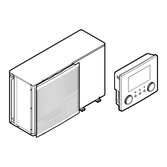
Page 14: About The Box
The transportation stay protects the unit during transport. During installation it must be removed. Prerequisite: Open the service cover. See "4.3.1 To open the outdoor unit" [ 4 17]. Installation manual EBLA09~16D + EDLA09~16D Daikin Altherma 3 M 4P620239-1B – 2022.05... -
Page 15: Unit Installation
Unit installation WARNING Make sure installation, servicing, maintenance and repair Preparing the installation site comply with instructions from Daikin and with applicable legislation and are executed ONLY by authorised persons. WARNING The appliance shall be stored so as to prevent mechanical... -
Page 16: To Install The Outdoor Unit
4 Fix the unit to the installation structure. Drain holes (dimensions in mm) Discharge side Distance between anchor points Bottom frame Knockout hole for snow Drain hole for safety valve Installation manual EBLA09~16D + EDLA09~16D Daikin Altherma 3 M 4P620239-1B – 2022.05... -
Page 17: To Install The Discharge Grille
To open the outdoor unit ▪ Water temperature. All installed piping and piping accessories (valve, connections,…) MUST withstand following DANGER: RISK OF ELECTROCUTION temperatures: DANGER: RISK OF BURNING/SCALDING EBLA09~16D + EDLA09~16D Installation manual Daikin Altherma 3 M 4P620239-1B – 2022.05... -
Page 18: To Check The Water Volume And Flow Rate
1 Connect the shut-off valve (with integrated filter) to the outdoor Cooling 20 l/min unit water inlet, using thread sealant. Heating/defrost when outdoor temperature is above –5°C Installation manual EBLA09~16D + EDLA09~16D Daikin Altherma 3 M 4P620239-1B – 2022.05... -
Page 19: To Fill The Water Circuit
To fill the water circuit WARNING To fill the water circuit, use a field supply filling kit. Make sure you comply with the applicable legislation. Ethylene glycol is toxic. EBLA09~16D + EDLA09~16D Installation manual Daikin Altherma 3 M 4P620239-1B – 2022.05... -
Page 20: To Fill The Domestic Hot Water Tank
(with λ=0.039 W/ piping from freezing. mK). ▪ Protection against freezing: the glycol will prevent the liquid inside the piping from freezing. Installation manual EBLA09~16D + EDLA09~16D Daikin Altherma 3 M 4P620239-1B – 2022.05... -
Page 21: Electrical Installation
>16 A and ≤75 A per phase.). Guidelines when connecting the electrical wiring Tightening torques Item Tightening torque (N•m) 2.45 ±10% 0.88 ±10% 0.88 ±10% 2.45 ±10% 0.88 ±10% 2.45 ±10% X10M 0.88 ±10% EBLA09~16D + EDLA09~16D Installation manual Daikin Altherma 3 M 4P620239-1B – 2022.05... - Page 22 See: Interface ▪ Installation and operation manual of the Human Comfort Interface ▪ Addendum book optional equipment Wires: 2×(0.75~1.25 mm²) Maximum length: 500 m [2.9] Control [1.6] Room sensor offset Installation manual EBLA09~16D + EDLA09~16D Daikin Altherma 3 M 4P620239-1B – 2022.05...
-
Page 23: To Connect The Electrical Wiring To The Outdoor Unit
In case of normal kWh rate power supply Normal kWh rate Wires: 1N+GND, OR 3N+GND power supply Maximum running current: Refer to name plate on unit. EBLA09~16D + EDLA09~16D Installation manual Daikin Altherma 3 M 4P620239-1B – 2022.05... - Page 24 1 Open the service cover. See "4.3.1 To open the outdoor unit" [ 4 17]. 2 Connect the preferential kWh rate power supply (1N~or 3N~ depending on model, see name plate). Installation manual EBLA09~16D + EDLA09~16D Daikin Altherma 3 M 4P620239-1B – 2022.05...
-
Page 25: To Connect The Backup Heater Power Supply
Overcurrent fuse (field supply). Recommended fuse: 2‑pole; 16 A; curve 400 V; tripping class C. Q1DI Earth leakage circuit breaker (field supply) X19A Terminal (field supply) X11YB X11Y X11YA X19A X11YA X11Y X11YB EBLA09~16D + EDLA09~16D Installation manual Daikin Altherma 3 M 4P620239-1B – 2022.05... -
Page 26: External Backup Heater Kit
1 Connect the backup heater power supply. A 4‑pole fuse is used for F1B. Example measure resistance between K1M/1 and K5M/13: 2 If required, modify the connection on terminal X14M. Installation manual EBLA09~16D + EDLA09~16D Daikin Altherma 3 M 4P620239-1B – 2022.05... - Page 27 EKMBHBP1 terminals as shown in the illustration below. is required if condensation is expected inside the backup heater. 9 10 X15M EKLBUHCB6W EBLA09~16D + EDLA09~16D Installation manual Daikin Altherma 3 M 4P620239-1B – 2022.05...
-
Page 28: To Connect The User Interface
▪ (if necessary) Opening the user interface after it is installed. Connecting the user interface cable to the outdoor unit Wires: 4×(0.75~1.25 mm²) Maximum length: 200 m Installation manual EBLA09~16D + EDLA09~16D Daikin Altherma 3 M 4P620239-1B – 2022.05... - Page 29 ▪ Align the positioning pins and push the front plate onto the rear plate until it moves into place with a click. ▪ The connector pins are automatically inserted correctly. ×2 ×2 Positioning pins Connector pins Front plate EBLA09~16D + EDLA09~16D Installation manual Daikin Altherma 3 M 4P620239-1B – 2022.05...
-
Page 30: To Connect The Shut-Off Valve
3 4 5 6 NOTICE Only connect NO (normally open) valves. X2M.3 X2M.4 (NO) 3 Fix the cable with cable ties to the cable tie mountings. Installation manual EBLA09~16D + EDLA09~16D Daikin Altherma 3 M 4P620239-1B – 2022.05... -
Page 31: To Connect The Domestic Hot Water Pump
2 Connect the alarm output cable to the appropriate terminals as shown in the illustration below. Wires connected to the alarm output A4P.Y2 Wire between X2M and A4P A4P Installation of EKRP1HBAA is required. X2M.7 A4P.Y1 X2M.7 EBLA09~16D + EDLA09~16D Installation manual Daikin Altherma 3 M 4P620239-1B – 2022.05... -
Page 32: To Connect The Changeover To External Heat Source
3 4 5 A4P.X1 A4P.X2 Installation of EKRP1AHTA is required. 3 Fix the cable with cable ties to the cable tie mountings. Installation manual EBLA09~16D + EDLA09~16D Daikin Altherma 3 M 4P620239-1B – 2022.05... -
Page 33: To Connect The Safety Thermostat (Normally Closed Contact)
▪ In case of low voltage Smart Grid contacts ▪ In case of high voltage Smart Grid contacts. This requires the installation of the Smart Grid relay kit (EKRELSG). EBLA09~16D + EDLA09~16D Installation manual Daikin Altherma 3 M 4P620239-1B – 2022.05... - Page 34 High voltage Smart Grid contact 2 ×4 X10M Relay for Smart Grid contact 1 Relay for Smart Grid contact 2 X10M Terminal block Screws for X10M Screws for K1A and K2A Installation manual EBLA09~16D + EDLA09~16D Daikin Altherma 3 M 4P620239-1B – 2022.05...
-
Page 35: Finishing The Outdoor Unit Installation
Installer pin code more detailed explanation and background information, The Installer pin code is 5678. Additional menu items and see the installer reference guide. installer settings are now available. EBLA09~16D + EDLA09~16D Installation manual Daikin Altherma 3 M 4P620239-1B – 2022.05... -
Page 36: Configuration Wizard
• [E-06]: Is a domestic hot water tank installed in the system? 6 Press the left dial to confirm the new setting. • [E-07]: What kind of domestic hot water tank is installed? Installation manual EBLA09~16D + EDLA09~16D Daikin Altherma 3 M 4P620239-1B – 2022.05... - Page 37 The auto emergency setting can be set in the menu ▪ the zone with the highest water temperature is structure of the user interface only. configured as the additional zone. EBLA09~16D + EDLA09~16D Installation manual Daikin Altherma 3 M 4P620239-1B – 2022.05...
-
Page 38: Configuration Wizard: Backup Heater
Backup heater type ▪ For models with integrated backup heater, this is fixed to 3V. Installation manual EBLA09~16D + EDLA09~16D Daikin Altherma 3 M 4P620239-1B – 2022.05... -
Page 39: Configuration Wizard: Main Zone
(e.g. heat pump convector). Room thermostat Unit operation is decided based on the ambient temperature of the dedicated Human Comfort Interface (BRC1HHDA used as room thermostat). EBLA09~16D + EDLA09~16D Installation manual Daikin Altherma 3 M 4P620239-1B – 2022.05... -
Page 40: Configuration Wizard: Tank
During Reheat only mode, the tank setpoint can be set on the user temperature minus the reheat hysteresis temperature, the tank heats interface. The maximum allowed temperature is determined by the up to the reheat temperature. following setting: Installation manual EBLA09~16D + EDLA09~16D Daikin Altherma 3 M 4P620239-1B – 2022.05... -
Page 41: Weather-Dependent Curve
8.3.2 2-points curve temperatures. Define the weather-dependent curve with these two setpoints: Examples ▪ Setpoint (X1, Y2) Weather-dependent curve when slope is selected: ▪ Setpoint (X2, Y1) EBLA09~16D + EDLA09~16D Installation manual Daikin Altherma 3 M 4P620239-1B – 2022.05... -
Page 42: Using Weather-Dependent Curves
Confirm changes and return to the submenu. temperatures … temperatures … Cold ↑ — 8.3.4 Using weather-dependent curves ↓ — Configure weather-dependent curves as following: Cold ↓ ↑ Cold Cold — ↑ Installation manual EBLA09~16D + EDLA09~16D Daikin Altherma 3 M 4P620239-1B – 2022.05... -
Page 43: Settings Menu
ON/OFF condition. 8.4.2 Additional zone Ext thermostat type Only applicable in external room thermostat control. For more info zone" [ 4 43]. about the functionality, see "8.4.1 Main EBLA09~16D + EDLA09~16D Installation manual Daikin Altherma 3 M 4P620239-1B – 2022.05... -
Page 44: Menu Structure: Overview Installer Settings
Averaging time [9.C] Bivalent Bivalent Boiler efficiency Temperature Hysteresis Only applicable in Swedish language. INFORMATION Depending on the selected installer settings and unit type, settings will be visible/invisible. Installation manual EBLA09~16D + EDLA09~16D Daikin Altherma 3 M 4P620239-1B – 2022.05... -
Page 45: Commissioning
The power supply voltage matches the voltage on the commissioning checklist is also available on the Daikin identification label of the unit. Business Portal (authentication required). There are NO loose connections or damaged electrical The general commissioning checklist is complementary to components in the switch box. -
Page 46: To Perform An Air Purge
For example, when you select Pump, a test run of the pump will start. Conditions: Make sure all operation is disabled. Go to [C]: Operation and turn off Space heating/cooling and Tank operation. Installation manual EBLA09~16D + EDLA09~16D Daikin Altherma 3 M 4P620239-1B – 2022.05... -
Page 47: 10 Hand-Over To The User
▪ Show the user what to do for the maintenance of the unit. ▪ Explain the user about energy saving tips as described in the operation manual. EBLA09~16D + EDLA09~16D Installation manual Daikin Altherma 3 M 4P620239-1B – 2022.05... -
Page 48: 11 Technical Data
11 Technical data Technical data A subset of the latest technical data is available on the regional Daikin website (publicly accessible). The full set of latest technical data is available on the Daikin Business Portal (authentication required). 11.1 Piping diagram: Outdoor unit EBLA09~16D▲3V3▼... - Page 49 Air heat exchanger Distributor Air heat exchanger, middle Heat exchanger Service port 5/16" flare Refrigerant flow: Accumulator Heating Muffler Cooling Connections: Screw connection Flare connection Quick coupling Brazed connection EBLA09~16D + EDLA09~16D Installation manual Daikin Altherma 3 M 4P620239-1B – 2022.05...
-
Page 50: Wiring Diagram: Outdoor Unit
# Domestic hot water pump (2) Hydro SWB layout (2) Hydro switch box layout # 2-way valve for cooling mode For external BUH option For external backup heater kit Installation manual EBLA09~16D + EDLA09~16D Daikin Altherma 3 M 4P620239-1B – 2022.05... - Page 51 For internal BUH option For models with integrated supplied by PCB) (voltage supplied by PCB) backup heater Space C/H On/OFF output Space cooling/heating ON/OFF Hydro Hydro module output Outdoor Outdoor EBLA09~16D + EDLA09~16D Installation manual Daikin Altherma 3 M 4P620239-1B – 2022.05...
- Page 52 * Terminal strip (booster heater power supply) # Terminal strip (power supply at client side) Terminal strip (integrated backup heater power supply) X10M * Terminal (high voltage Smart Grid) Connector Terminal strip Installation manual EBLA09~16D + EDLA09~16D Daikin Altherma 3 M 4P620239-1B – 2022.05...
- Page 53 A11P: X1B: P2-P1 A11P: X10 A8P: X801M: 3-5 4 core signal X5M: 15-16 A11P: X1B: +12V- –12V 2 core Power limitation demand input 4 A8P: X801M: 4-5 signal 4D128841C EBLA09~16D + EDLA09~16D Installation manual Daikin Altherma 3 M 4P620239-1B – 2022.05...
- Page 56 4P620239-1 B 0000000- 4P620239-1B 2022.05 Verantwortung für Energie und Umwelt...