Crestron CHV-THSTAT Operation And Installation Manual
Crestron operations and installation guide thermostats chv-tstat, chv-thstat
Hide thumbs
Also See for CHV-THSTAT:
- Operation and installation manual (100 pages) ,
- Quick start manual (4 pages) ,
- Dimension manual (38 pages)
Table of Contents
Advertisement
Quick Links
Advertisement
Table of Contents

Related Manuals for Crestron CHV-THSTAT


Summary of Contents for Crestron CHV-THSTAT
- Page 1 Crestron CHV-TSTAT & CHV-THSTAT Thermostats Operations and Installation Guide...
- Page 2 This document was prepared and written by the Technical Documentation department at: Crestron Electronics, Inc. 15 Volvo Drive Rockleigh, NJ 07647 1-888-CRESTRON All brand names, product names and trademarks are the property of their respective owners. ©2003 Crestron Electronics, Inc.
-
Page 3: Table Of Contents
Crestron CHV-TSTAT and CHV-THSTAT Contents Quick Installation Reference ...ii Thermostats: CHV-TSTAT and CHV-THSTAT Introduction ... 1 Functions and Features ... 1 Specifications ... 3 Physical Description... 4 Industry Compliance ... 6 Setup ... 7 Network Wiring... 7 Identity Code ... 7 System Connections ... -
Page 4: Quick Installation Reference
2. Separate the thermostat from the backplate to expose the connections and mounting holes. 3. Mount the thermostat backplate (60 inches above the finished floor) directly to the wall with wall anchors (not provided) and screws (not provided) or to a single-gang box (not provided) mounted horizontally, and connect the wiring. -
Page 5: Thermostats: Chv-Tstat And Chv-Thstat
CHV-THSTAT Introduction Functions and Features The CHV-TSTAT and CHV-THSTAT series are wall-mounted universal thermostats that can be part of a Crestron Home capable of controlling one or two-stage heating and cooling systems. Each thermostat is available in three colors: almond, black and white. The suffix ‘A’, ‘B’, and ‘W’, respectively denotes color, e.g., CHV-TSTATB is a black unit. -
Page 6: Remote Sensors
Guide (Doc. 8189), which is available from the Crestron website (www.crestron.com). NOTE: The CHV-TSTAT and CHV-THSTAT allow the user to set a temperature that the heating and/or cooling system maintains. This is called the “Set Point”. Refer to “Operating the Thermostat” on page 21 for more information. -
Page 7: Specifications
(e.g., S, V, W, X). Filenames for CHV update files have a UPG extension and are in one zipped UPG file. The ‘x’ in the file name refers to the version number. Thermostats: CHV-TSTAT and CHV-THSTAT • 3 Thermostats DETAILS... -
Page 8: Physical Description
The back of the unit has ventilation slots, and holes for mounting the unit and wiring. The ventilation slots must be unobstructed for airflow to the unit. Physical View of CHV-TSTAT and CHV-THSTAT Current Temperature Current Humidity 1.75 in... - Page 9 Connection View (Backplate, view from the front with cover removed) Ports The CHV-TSTAT and CHV-THSTAT have four types of connections on the inside back plate (refer to graphic above). NETWORK (Optional) – provides communication to the control system and Cresnet power to the CHV-TSTAT and CHV-THSTAT.
-
Page 10: Industry Compliance
There are four buttons used to setup and adjust the thermostat. NOTE: When MODE and VIEW are pressed together and held for five seconds, the thermostat enters the system setup mode (refer to “Thermostat Setup” on page 16). Industry Compliance... -
Page 11: Setup
SIMPL Windows or D3 Pro program. Refer to “Device Options” on page 18 for a description of assigning the NET ID to the thermostat and “Setting the Net ID in Device Settings” on page 26 for an example of the SIMPL Windows procedure. -
Page 12: System Connections
Thermostats System Connections Backplate - view from the front with the cover removed 8 • Thermostats: CHV-TSTAT and CHV-THSTAT Crestron CHV-TSTAT and CHV-THSTAT HUM - Energized to RHU during humidity call RHU - Reference for humidifier RSR - Remote Sensor Returns - Common sensor terminal... -
Page 13: Wiring Diagrams
NOTE: Ensure that the power circuits are shut off at the source before connecting the thermostat. Provide disconnect means and overload protection as required for the power supply. NOTE: Ensure that the transformer has sufficient power for all the thermostats in the system, or use multiple transformers. -
Page 14: Three-Wire Heating System Connections
Thermostats Three-Wire Heating System Connections Backplate Thermostat Circuit Board 10 • Thermostats: CHV-TSTAT and CHV-THSTAT Crestron CHV-TSTAT and CHV-THSTAT NETWORK CRESTRON ELECTRONICS Operations and Installation Guide – DOC. 8163A Integrated Control Unit Jumper on P4 between pins 1 and 2... -
Page 15: Five-Wire Heating/Cooling System Connections
Five-Wire Heating/Cooling System Connections Backplate Jumper From RH to RC Thermostat Circuit Board Operations and Installation Guide – DOC. 8163A NETWORK CRESTRON ELECTRONICS Thermostats: CHV-TSTAT and CHV-THSTAT • 11 Thermostats Integrated Control Unit Jumper on P4 between pins 1 and 2... -
Page 16: Heat Pump Connections (Single & Two-Stage)
RC Thermostat Circuit Board NOTE: For wiring details, refer to the general Heat Pump schematic on the following page. 12 • Thermostats: CHV-TSTAT and CHV-THSTAT Crestron CHV-TSTAT and CHV-THSTAT NETWORK CRESTRON ELECTRONICS Operations and Installation Guide – DOC. 8163A... - Page 17 Fan Relay Stage Compressor StageCompressor Changeover Valve Heat Pump Transformer 120 VAC 24 VAC Aux Heat Transformer Aux Heat Relay 120 VAC 24 VAC Operations and Installation Guide – DOC. 8163A Thermostats Thermostats: CHV-TSTAT and CHV-THSTAT • 13 Backplate NETWORK...
-
Page 18: Installation
CHV-THSTAT. NOTE: When installing directly on drywall, use anchoring screws and hardware. Make sure the back of the thermostat is flush with drywall and the unit is level. Required Hardware NOTE: Ensure the correct position of the P4 jumper; refer to pages 10, 11 and 12. - Page 19 Operations and Installation Guide – DOC. 8163A Panhead 6/32 x 1 in Installation view – Direct mount to wall Mounting Screws (not provided) Thermostats: CHV-TSTAT and CHV-THSTAT • 15 Thermostats Stud Single-gang electrical box (not provided) Wall Anchors (not provided)
-
Page 20: Thermostat Setup And Operation
Thermostats Thermostat Setup and Operation Setup Procedure After the thermostat is installed, it is necessary to set it up. Follow these directions. Press and hold the MODE and VIEW buttons simultaneously for five seconds to access the setup menus. The following SETUP screens appear in this order: Use the MODE button to advance to the next setup screen. - Page 21 Requires an outdoor temperature sensor. Run Fan in Heat Calls? Yes or No Most heating systems run the fan automatically. If your heating system requires fan control, select Yes. Thermostats: CHV-TSTAT and CHV-THSTAT • 17 Thermostats...
- Page 22 (for example: lights, alarms, etc.). Each of the two pages has two definable buttons. The up ▲and down ▼ keys are set by indirect text for each page, refer to “CHV-TSTAT and CHV-THSTAT Advanced Symbol” on page 26.
-
Page 23: Display Options
OMIT to exclude each sensor in the averaging equation. Choose OMIT if the remote sensors are not installed. NOTE: The thermostat will not leave the setup mode unless a valid sensor selection is made. An omitted remote humidity sensor for a CHV-TSAT does not prevent setup exit. - Page 24 Choose Off, H1, or H2 Cool Call Choose Off, C1 or C2 Aux Heat (ON or Off) Only appears on heat pump systems Humidifier Call (On or Off) CHV-THSTAT only Fan Run Call (ON or OFF) Operations and Installation Guide – DOC. 8163A...
-
Page 25: Operating The Thermostat
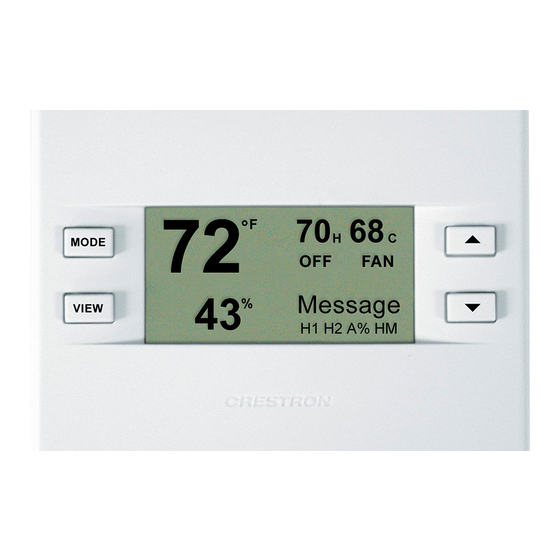
Operations and Installation Guide – DOC. 8163A The Main Screen displays the Current Temperature, System Mode, Fan Mode, and Set Point temperatures. The CHV-THSTAT also displays Relative Humidity and Humidifier Mode. Press the up ▲arrow button to increase the set point temperature. Press the down ▼arrow button to decrease the set point temperature. - Page 26 Press the VIEW button to display the “Humidity” screen. Use the up ▲and down ▼arrow buttons to adjust the Humidity Set Point level (CHV-THSTAT only). This page only appears if enabled in the setup. Refer to “HUMIDIFIER/FAN OPTIONS” on page 17.
- Page 27 Refer to “SCREEN OPTIONS” on page 18. NOTE: This is only a display and not for system activation. This display can be shown on either the CHV-TSTAT or the CHV-THSTAT. 3. MESSAGES Press the VIEW button again to display the “Messages” screen. This screen allows the user to view any text messages sent from the control system (Only when part of a Cresnet system).
-
Page 28: Programming Software
Thermostats Programming Software Have a comment about Crestron The CHV-TSTAT and CHV-THSTAT thermostats do not require programming software? when used as stand alone devices. Programming as part of a Cresnet system allows additional functionality, including: Direct software related suggestions and/or complaints to Crestron via Global Update and Global Page display –... -
Page 29: Programming With Crestron D3 Pro
The System Views lower pane displays the PRO2 system tree. This tree can be expanded to display and configure the communications ports. Expanded PRO2 System Tree Operations and Installation Guide – DOC. 8163A Thermostats ® environment. Thermostats: CHV-TSTAT and CHV-THSTAT • 25... - Page 30 Thermostats C2Net-Device Slot in Configuration Manager To incorporate a CHV-THSTAT or CHV-TSTAT into the system, drag one of the symbols for the thermostat from the Crestron Sensing Modules folder of the Device Library and drop it on C2-NET Device slot in System Views. The PRO2 system tree displays the thermostat symbol in Slot 9, with a default NET ID of 2A as shown in the example graphic below.
- Page 31 The following diagram shows the basic thermostat symbols in the SIMPL Windows’ Programming Manager. Refer to page 31 for a detailed description of the inputs and outputs Detail View of the Basic CHV-THSTAT and CHV-TSTAT Symbol Digital Inputs/Outputs Detail View of the Basic CHV-THSTAT and CHV-TSTAT Symbol Analog Inputs/Outputs Operations and Installation Guide –...
- Page 32 The advanced symbol allows additional functionality, including: Global Update and Global Page display, Function pages, and System Messaging. Refer to page 31 for a detailed description of the inputs and outputs. Detail View of the Advanced CHV-THSTAT and CHV-TSTAT Symbol Digital Inputs/Outputs 28 • Thermostats: CHV-TSTAT and CHV-THSTAT Crestron CHV-TSTAT and CHV-THSTAT Operations and Installation Guide –...
- Page 33 Crestron CHV-TSTAT and CHV-THSTAT Operations and Installation Guide – DOC. 8163A Detail View of the Advanced CHV-THSTAT and CHV-TSTAT Symbol Digital Outputs Thermostats: CHV-TSTAT and CHV-THSTAT • 29 Thermostats...
- Page 34 Thermostats Crestron CHV-TSTAT and CHV-THSTAT Detail View of the Advanced CHV-THSTAT and CHV-TSTAT Symbol Analog Inputs/Outputs Detail View of the Advanced CHV-THSTAT and CHV-TSTAT Symbol Serial Inputs 30 • Thermostats: CHV-TSTAT and CHV-THSTAT Operations and Installation Guide – DOC. 8163A...
- Page 35 Thermostat Symbol Definitions The following tables contain a detailed description of the inputs and outputs for the basic and advanced CHV-TSTAT and CHV-THSTAT symbols. NOTE: For the simplest possible programming, connect an appropriate analog signal to SETPOINT_1, and possibly SETPOINT_2.
- Page 36 47. Signal Name HUMIDIFIER_EN HUMIDIFIER_EN_F HUM_SETPOINT HUM_SETPOINT_F OUTDOOR_HUM OUTDOOR_HUM_F INDOOR_HUM 32 • Thermostats: CHV-TSTAT and CHV-THSTAT Crestron CHV-TSTAT and CHV-THSTAT Symbol Definition Advanced Output Output that is asserted when the global update “send” button is pressed Advanced Input Causes the front panel third text line to flash “view msg”...
- Page 37 "use" in set-up. This output is only active when a thermostat setup has humidity sensing capability, either by being a CHV-THSTAT or a CHV-TSTAT with humidity remote (Analog) Output Humidity value of built-in sensor (Analog) Output will send out the sensor values even if the sensor is declared, "omit"...
- Page 38 AUX_BALANCE_PT_F LCD_CONTRAST_F TEMP_DISP_OFFSET_F Setup Related Digital Joins Signal Name HEAT_COOL SYS_F HEATPUMP_SYS_F 34 • Thermostats: CHV-TSTAT and CHV-THSTAT Crestron CHV-TSTAT and CHV-THSTAT Symbol Definition Both Output Temperature used for regulation, this is the mean (averaged) temperature for all sensors declared “use”, in...
- Page 39 (OD) Asserted when remote 2 temperature sensor has been Output declared as outdoor (OD) Output Asserted when using built in humidity sensor (THSTAT) Output Asserted when using remote 1 humidity sensor Thermostats: CHV-TSTAT and CHV-THSTAT • 35 Thermostats...
-
Page 40: Viewport Id String
Advanced Example Programs Example programs for the thermostat are available from the Crestron FTP site (ftp://ftp.crestron.com). Select the Examples Folder and search for: CHV-THSTAT sample with scheduler.zip. Viewport ID String In Viewport, the thermostats output a string of characters that describe the setup and configuration of the thermostat. -
Page 41: Problem Solving
Thermostats: CHV-TSTAT and CHV-THSTAT • 37 Thermostats CORRECTIVE ACTION Check for +24V on pins 24(C) and 24(R) Check thermostat mounting... -
Page 42: Further Inquiries
Updates are available from the Download | Product Manuals section and are identified as an “Addendum” in the Download column. 38 • Thermostats: CHV-TSTAT and CHV-THSTAT Crestron CHV-TSTAT and CHV-THSTAT • In the US and Canada, call Crestron’s corporate headquarters at 1-888-CRESTRON [1-888-273-7876]. -
Page 43: Appendix A: Glossary
BTU - British Thermal Unit – In scientific terms, it represents the amount of Call – A call is when the thermostat requests the heating or cooling system to turn Damper – Found in ductwork, this movable plate opens and closes to control Dead Band –... -
Page 44: Appendix B: About Heat Pumps
40 • Thermostats: CHV-TSTAT and CHV-THSTAT Crestron CHV-TSTAT and CHV-THSTAT Operations and Installation Guide – DOC. 8163A... -
Page 45: Return And Warranty Policies
All brand names, product names, and trademarks are the sole property of their respective owners. Windows is a registered trademark of Microsoft Corporation. Windows95/98/Me/XP and WindowsNT/2000 are trademarks of Microsoft Corporation. Operations and Installation Guide – DOC. 8163A Thermostats Thermostats: CHV-TSTAT and CHV-THSTAT • 41... - Page 46 Thermostats Crestron CHV-TSTAT and CHV-THSTAT This page intentionally left blank. 42 • Thermostats: CHV-TSTAT and CHV-THSTAT Operations and Installation Guide – DOC. 8163A...
- Page 47 Crestron CHV-TSTAT and CHV-THSTAT Thermostats This page intentionally left blank Thermostats: CHV-TSTAT and CHV-THSTAT • 43 Operations and Installation Guide – DOC. 8163A...
- Page 48 Crestron Electronics, Inc. Operations and Installation Guide – DOC. 8163A 15 Volvo Drive Rockleigh, NJ 07647 04.03 Tel: 888.CRESTRON Fax: 201.767.7576 Specifications subject to www.crestron.com change without notice.