Table of Contents
Advertisement
Quick Links
Repair - Parts
Electric Motor for
SaniSpray HP
Electric motor for use with SaniSpray HP 750. Not approved for use in explosive
atmospheres or hazardous (classified) locations. For professional use only.
Important Safety Instructions
Read all warnings and instructions in this
manual and related manuals before using
the equipment. Save these instructions.
Model 273199
844-241-9499
Use only genuine Graco replacement parts.
The use of non-Graco replacement parts may void warranty.
™
750
3A7940A
EN
Advertisement
Table of Contents

Related Manuals for Graco 273199


Summary of Contents for Graco 273199
- Page 1 (classified) locations. For professional use only. Important Safety Instructions Read all warnings and instructions in this manual and related manuals before using the equipment. Save these instructions. Model 273199 844-241-9499 Use only genuine Graco replacement parts. The use of non-Graco replacement parts may void warranty.
-
Page 2: Table Of Contents
Replace Fan Assembly ....10 Graco Warranty ......26 Replace Electronics Cover. -
Page 3: Important User Information
Important User Information Important User Information Before using your disinfectant You must also read and follow the information sprayer, read this manual for on the disinfectant container label and ask for complete instructions on proper use a Safety Data Sheet (SDS) from your supplier. and safety warnings. -
Page 4: Warnings
Warnings Warnings The following warnings are for the setup, use, grounding, maintenance, and repair of this equipment. The exclamation point symbol alerts you to a general warning and the hazard symbols refer to procedure-specific risks. When these symbols appear in the body of this manual or on warning labels, refer back to these Warnings. Product-specific hazard symbols and warnings not covered in this section may appear throughout the body of this manual where applicable. - Page 5 Warnings WARNING ELECTRIC SHOCK HAZARD This equipment must be grounded. Improper grounding, setup, or usage of the system can cause electric shock. • Turn off and disconnect power cord before servicing equipment. • Connect only to grounded electrical outlets. • Use only 3-wire extension cords.
-
Page 6: Component Identification
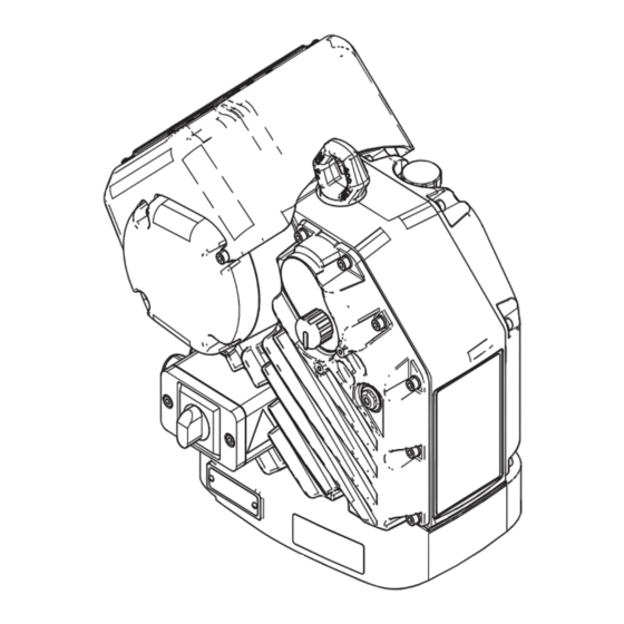
Component Identification Component Identification Motor Components . 1: Motor Component Identification Ref. Description Ref. Description Oil Level Sight Glass Electric Motor Fan Cord Grip Power Switch Power Cord Grip Pressure Adjustment Knob Oil Drain Plug Status Indicator Light (LED) Ground Screw Oil Fill Cap (vented) Junction Box Cover Junction Box... -
Page 7: Sprayer Components
Component Identification Sprayer Components . 2: Sprayer Component Identification Ref. Description Ref. Description Rupture Disc Electric Motor Oil Fill Cap (vented) Pump Junction Box Disinfectant Inlet Hopper Packing Nut Hopper Bracket Power Switch Airless Hose Disinfectant Outlet Tip and Tip Guard Assembly 4-gun manifold Pressure Adjustment Knob Gun Extension... -
Page 8: Repair
Repair Repair 4. Reinstall the oil drain plug (15). Torque to 18-23 ft-lb (25-30 N•m). The pump remains pressurized until pressure is manually relieved. To help prevent serious injury from pressurized fluid, such as skin injection, disinfectant splashing and moving parts, follow the Pressure Relief Procedure detailed in your sprayer manual. -
Page 9: Replace Fan Fuses
3. Unscrew the fuse holder (FH), remove the old fuse, and replace it with a new 5 mm x 20 mm, 500 mA, 250V, Slow Blow fuse (Graco part 116682). Reconnect the fuse holder and tighten into place. 3A7940A... -
Page 10: Replace Fan Assembly
Repair 5. Remove the grounding screw (GS) and disconnect Replace Fan Assembly the green grounding wire coming out of the fan cord grip (C1) attached to the motor (A), not the junction 1. Follow the Prepare the Motor for Repair procedure box. - Page 11 Repair 8. Install the new fan assembly (FA). To reattach the fan 11. Use a ferrule to connect each fan wire to one of the assembly, slide it into the slots for tabs located on the two wires coming out of the motor grommet. Then junction box side and gently push down the far end of attach one wire set into the disconnect box location the assembly.
-
Page 12: Replace Electronics Cover
Repair 5. Unscrew the ground screws from the fan and power Replace Electronics Cover cord ground wires. Removal 1. Follow the Prepare the Motor for Repair procedure on page 8. 2. Remove the pump (B) from the sprayer. See your Pump manual. - Page 13 Repair 7. Use an adjustable wrench to loosen the fan cord grip 11. Carefully tilt the electronics cover (50) down. (C1). NOTICE 8. Pull the fan wires out through the cord grip. All wires must be disconnected before the cover is completely removed.
- Page 14 Repair 14. Disconnect the encoder wire (EW). 15. Discard the used cover gasket (54) and the junction box gasket (52). 3A7940A...
- Page 15 Repair 6. Connect the fan ground wire. Installation 7. Use an adjustable wrench to tighten the fan cord grip 1. Install the new cover gasket (54) included in the (C1). electronics cover kit. Reconnect all wires. 8. Install the gasket (52), junction box sleeve (101), and tighten the four bolts (20).
- Page 16 Repair 4. The motor shaft (MS) will run up and down slowly Calibration over the course of several minutes. NOTE: The motor (A) must be de-coupled from the pump and must be able to cycle freely with no 5. Midway through the auto-calibration process, the obstructions.
-
Page 17: Repair Token Cable
Repair 6. Install the cover (50) and tighten the twelve screws Repair Token Cable (20) and washers. Torque to 15-20 ft-lb (20-27 N•m). 1. Follow the Prepare the Motor for Repair procedure on page 8. 2. Remove the electronics cover. See Replace Electronics Cover on page 12. -
Page 18: Update Software
Repair 6. The red indicator light (L) will flash while the software Update Software is being loaded (approximately 30 seconds). When the software is completely loaded, the red light will 1. Follow the Prepare the Motor for Repair procedure turn off for four seconds before the software version on page 8. -
Page 19: Change The Oil
NOTICE be found by searching “Software Version Change Do not over-torque. The drain plug can become History for 273199” at Graco Technical Support. Contact stripped and damaged. a technical support representative before upgrading. 4. Position the sprayer on a level surface. Fill until the oil level is near the halfway point of the sight glass (BB). -
Page 20: Parts
Parts Parts Electric Motor . 3: Electric Motor Parts 3A7940A... -
Page 21: Parts List - Electric Motor (273199)
Parts Parts List - Electric Motor (273199) Ref. Part Description Qty. Ref. Part Description Qty. 127463 SCREW, cap, socket head - - - - - CHASSIS 101‡ 17B505 SLEEVE, junction box 15H392 ADAPTER, rod Xtreme 17B553 ERROR CODE LABEL 5†... -
Page 22: Mounting Hole Pattern
Parts Mounting Hole Pattern . 4: Mounting Hole Pattern 6.186 in. (157 mm) 6.186 in. (157 mm) Four 3/8-16 Mounting Holes Six 5/8-11 Tie Rod Holes: • 8 in. (203 mm) x 120° bolt circle • 5.9 in. (150 mm) x 120° bolt circle 3A7940A... -
Page 23: Wiring Diagram
Wiring Diagram Wiring Diagram . 5: Wiring Diagram 3A7940A... -
Page 24: Dimensions
Dimensions Dimensions . 6: Motor Dimensions Ref. Motor Dimensions A width 15.3 in. (39 cm) B depth 18.3 in. (47 cm) C mounted height 18.3 in. (47 cm) D total height 21.5 in. (55 cm) 3A7940A... -
Page 25: Technical Specifications
Input current 20A maximum Oil capacity* 1.5 quarts 1.4 liters Oil specification* Graco part number 16W645 ISO 220 silicone-free synthetic EP gear oil† 4200 lbf 18.7 kN Maximum force Notes * The motor gear-box is shipped from the factory pre-filled with oil. Additional oil must be purchased separately. -
Page 26: Graco Warranty
Graco warrants all equipment referenced in this document which is manufactured by Graco and bearing its name to be free of defects in material and workmanship on the date of sale by an authorized Graco distributor to the original purchaser for use. Graco will, for a period of ninety (90) days from the date of sale, provide repair parts for equipment determined by Graco to be defective.