
Related Manuals for JUKI MO-2000 Series


Summary of Contents for JUKI MO-2000 Series
- Page 1 2-Needle, 2/3/4-Thread Overlock Sewing Machine MO-2000 Series SERVICE MANUAL No.00 40267028...
-
Page 3: Table Of Contents
CONTENTS SPECIFICATIONS ................1 NAME OF EACH COMPONENT ............. 2 1. Appearance ......................... 2 2. Inside of the cover ...................... 3 STANDARD ADJUSTMENT / DISASSEMBLY AND ASSEMBLY... 4 1. Removing the top cover..................... 4 2. Removing the cloth plate cover ................6 3. - Page 4 27. Position of the needle thread take-up thread guide ..........48 28. Tension of the belt ....................50 29. Adjusting the needle bar connection guide of the needle threader ....52 30. Adjusting the needle threader hook ..............54 31. Adjusting the looper threader timing ..............56 32.
-
Page 5: Specifications
SPECIFICATIONS Items Description Model name 2-Needle, 2/3/4-Thread Overlock Sewing Machine (with differential feed adjusting) Stitch choice 2 needles, 4 thread overlock 2 needles, 3 thread overlock 1 needle, 3 thread overlock 1 needle, 2 thread overlock Sewing speed Up to 1,500 sti/min Rating 1,350±150 sti/min Needle gauge Overlocking: 2.2 mm... -
Page 6: Name Of Each Component
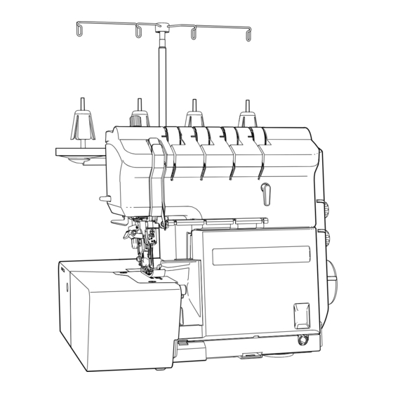
NAME OF EACH COMPONENT 1. Appearance Thread guide support Retractable support rod Open thread guide Lower looper thread tension dial Thread guide No. 1 Upper looper thread tension dial Magnet needle tray Right needle thread tension dial Micro-lifter dial *1 Left needle thread tension dial Top cover Spool holder pin... -
Page 7: Inside Of The Cover
2. Inside of the cover Front face Safety switch Needle threading mechanism Looper threading mechanism Knee lifting mechanism Knife Safety switch Rear face Micro lifting mechanism *1 Knee lifting mechanism Power PCB Motor Air pump motor *1: Only for MO-2500 type –... -
Page 8: Standard Adjustment / Disassembly And Assembly
STANDARD ADJUSTMENT / DISASSEMBLY AND ASSEMBLY Assembly should be carried out in the reverse order of the disassembly procedure. 1. Removing the top cover ○ Remove roll hemming thread tension lever ❶ by pulling it out toward you. ○ Loosen presser foot pressure regulator knob ❷ and remove it. ○... - Page 9 ○ Remove one screw ❹ to remove the thread stand. ○ Remove two screws ❺ to remove the thread stand base. ○ Remove two screws ❻ . ○ While lifting up the rear side of the top cover, remove it by prying out the claws on the side face (at four locations on the right and left) with a flat-blade screwdriver or the like.
-
Page 10: Removing The Cloth Plate Cover
2. Removing the cloth plate cover ○ Remove two screws ❶ of the bottom plate. ○ Remove one screw ❷ from the rear side face of the cloth plate. ○ For the cloth plate front and rear parts of which are hinged together, remove two safety switch setscrews ❸... -
Page 11: Removing The Bottom Plate
3. Removing the bottom plate ○ Remove four screws ❶ of the bottom plate. ○ Remove the bottom plate and remove three screws ❷ . Bottom face ❶ ❷ 4. Removing the looper cover ○ Remove two screws ❶ of the looper cover. Bottom face ❶... -
Page 12: Removing The Side Cover
5. Removing the side cover ○ Remove three screws ❶ from the rear face of the sewing machine. ○ Remove the side cover by pushing it forward so that it is disengaged from the claws located on the front side of the sewing machine. -
Page 13: Removing The Rear Cover Removing The
6. Removing the rear cover Removing the front cover ○ Remove one screw ❶ from the rear face of the sewing machine. ○ Remove setscrews ❶ , one each from the upper front part and upper side part of the sewing machine. ○... - Page 14 ○ Insert a flat-blade screwdriver into the groove in the pocket portion, and turn it by prying forward to disengage the rear cover from the claw. ○ Remove two screws ❸ from the front face of the sewing machine, and remove Claws the front cover and rear cover.
-
Page 15: Removing The Looper Cover Guide
7. Removing the looper cover guide ○ Remove the setscrews ❶ . ○ Remove the cover with the knife changeover lever aligned with the position of notch on the cover. ❶ ❶ – –... -
Page 16: Installation Of The Throat Plate
9. Installation of the throat plate WARNING : To protect against possible personal injury due to abrupt start of the machine, be sure to start the following work after turning the power off and ascertaining that the motor is at rest. Standard adjustment + 0.6 - 0.2... - Page 17 Adjustment Procedure Results of Improper Adjustment Checking items: ❶ Throat plate ❷ Setscrew ❸ Feed dog ❹ Thread sliding segment * Check that all needles are laterally equidistant with respect to the throat plate slot (A). * Check that the distance between the needle center and the front edge + 0.6 of the throat plate slot is 1.4 mm (B).
-
Page 18: Height Of The Needle Bar
10. Height of the needle bar WARNING : To protect against possible personal injury due to abrupt start of the machine, be sure to start the following work after turning the power off and ascertaining that the motor is at rest. Standard adjustment ❶... - Page 19 Adjustment Procedure Results of Improper Adjustment Checking items: ❶ Right hand needle ❷ Throat plate * Check that the distance between the throat plate surface and the OL right hand needle point with the needle bar at the highest point of its stroke is 11.16 ±...
-
Page 20: Position Of The Feed Dog
11. Position of the feed dog WARNING : To protect against possible personal injury due to abrupt start of the machine, be sure to start the following work after turning the power off and ascertaining that the motor is at rest. Standard adjustment Interference should be prevented ❶... - Page 21 Adjustment Procedure Results of Improper Adjustment Checking items: ❶ Main feed dog ❷ Sub feed dog ❸ Throat plate * Check that the feed dog and the slot in the throat plate ❸ are parallel If the clearances on the right side with each other, that the clearances on the right and left side of the and left side of the feed dog are feed dog are equal (A).
-
Page 22: Adjusting The Stroke Of The Sub Feed Dog
12. Adjusting the stroke of the sub feed dog WARNING : To protect against possible personal injury due to abrupt start of the machine, be sure to start the following work after turning the power off and ascertaining that the motor is at rest. Standard adjustment ❶... - Page 23 Adjustment Procedure Results of Improper Adjustment Checking items: ❶ Main feed dog ❷ Sub feed dog ❸ Throat plate * Adjust the stitch length to 4 mm. If the difference in the aforemen- * Set the differential feed ratio at "N". tioned clearances deviates from * Turn the handwheel to move the feed dog up and down.
-
Page 24: Height Of The Feed Dog
13. Height of the feed dog WARNING : To protect against possible personal injury due to abrupt start of the machine, be sure to start the following work after turning the power off and ascertaining that the motor is at rest. Standard adjustment ❶... - Page 25 Adjustment Procedure Results of Improper Adjustment Checking items: ❶ Front end of feed dog ○ If the sub feed dog height is * Adjust the stitch length to 2.5 mm. Set the differential feed ratio at "N". Bring the sub feed dog to its highest position. At this time, check that larger than the standard ad- the height of foremost section ❶...
-
Page 26: Feed Dog Timing
14. Feed dog timing WARNING : To protect against possible personal injury due to abrupt start of the machine, be sure to start the following work after turning the power off and ascertaining that the motor is at rest. Standard adjustment ❶... - Page 27 Adjustment Procedure Results of Improper Adjustment Checking items: ❶ Right hand needle ❷ Throat plate ❸ Sub feed dog * Adjust the stitch length to 2.5 mm. Set the differential feed ratio at "N". If this timing is not properly adjust- When sub feed dog ❸...
-
Page 28: Position Of The Balance Weights And The Cams
15. Position of the balance weights and the cams WARNING : To protect against possible personal injury due to abrupt start of the machine, be sure to start the following work after turning the power off and ascertaining that the motor is at rest. Standard adjustment ❺... - Page 29 Adjustment Procedure Results of Improper Adjustment ❶ Knife driving cam ❷ Feed cam ❸ Lower looper cam ❹ Upper looper cam ❺ Needle driving cam ○ Screw No. 1 is tightened in the flat section of the main shaft (the figure below). ❻...
-
Page 30: Projecting Amount Of The Upper Looper
16. Projecting amount of the upper looper WARNING : To protect against possible personal injury due to abrupt start of the machine, be sure to start the following work after turning the power off and ascertaining that the motor is at rest. Standard adjustment (A) 6.8 ±... - Page 31 Adjustment Procedure Results of Improper Adjustment Checking items: ❶ Left hand needle If the standard adjustment value is ❷ Upper looper exceeded, stitch skipping can be caused. * Check that distance (projecting amount) A from the left end of left hand needle ❶...
-
Page 32: Radius Of The Lower Looper
17. Radius of the lower looper WARNING : To protect against possible personal injury due to abrupt start of the machine, be sure to start the following work after turning the power off and ascertaining that the motor is at rest. Standard adjustment ❸... - Page 33 Adjustment Procedure Results of Improper Adjustment Checking items: ❶ Lower looper setscrew ❷ Lower looper shaft ❸ Lower looper * Check that the distance from the center of the lower looper shaft ❷ to the lower blade point is 65.5 ± 0.15 mm (A). How to perform adjustment: ○...
-
Page 34: Adjustment Of The Loop Lift
18. Adjustment of the loop lift WARNING : To protect against possible personal injury due to abrupt start of the machine, be sure to start the following work after turning the power off and ascertaining that the motor is at rest. Standard adjustment ❹... - Page 35 Adjustment Procedure Results of Improper Adjustment Checking items: ❶ Right hand needle ❷ Lower looper blade point ❸ Lower looper ❹ Gauge needle (Cut the top end of needle for use. L = 31.58 mm) * Check that the clearance between the needle ❶ and the lower looper If the clearance between the nee- blade point ❷...
-
Page 36: Timing Between Upper And Lower Looper
19. Timing between upper and lower looper WARNING : To protect against possible personal injury due to abrupt start of the machine, be sure to start the following work after turning the power off and ascertaining that the motor is at rest. Standard adjustment ❷... - Page 37 Adjustment Procedure Results of Improper Adjustment Checking items: ❶ Lower looper ❷ Upper looper * Check that the clearance between the projecting part of the lower looper ❶ and the blade point of the upper looper ❷ is 1 ± 0.5 mm (A) when the upper looper goes up and the upper looper blade point meets the lower looper.
-
Page 38: Installation Of The Needle Guards
20. Installation of the needle guards WARNING : To protect against possible personal injury due to abrupt start of the machine, be sure to start the following work after turning the power off and ascertaining that the motor is at rest. Standard adjustment ❸... - Page 39 Adjustment Procedure Results of Improper Adjustment Checking items: ❶ Throat plate ❷ Rear movable needle guard ❸ Front needle guard * Check that the clearance between the needle and the front needle guard and that between the needle and the rear movable needle guard are 0.05 to 0.2 mm (A) and 0 to 0.1 mm (E).
-
Page 40: Adjusting The Looper Thread Take-Up
21. Adjusting the looper thread take-up WARNING : To protect against possible personal injury due to abrupt start of the machine, be sure to start the following work after turning the power off and ascertaining that the motor is at rest. Standard adjustment ❶... - Page 41 Adjustment Procedure Results of Improper Adjustment Checking items: ❶ Looper thread take-up thread guide * The standard position of the looper thread take-up is the center of the slot. How to perform adjustment: ○ Loosen the setscrews (A). ○ Move thread guide ❶ to the right and left. ○...
-
Page 42: Height And Lateral Position Of The Presser Foot
22. Height and lateral position of the presser foot WARNING : To protect against possible personal injury due to abrupt start of the machine, be sure to start the following work after turning the power off and ascertaining that the motor is at rest. Standard adjustment (A) 5.8 to 6.0 mm ❶... - Page 43 Adjustment Procedure Results of Improper Adjustment Checking items: ❶ Throat plate * Raise the presser foot using the lifting lever and check that the dis- If the height of the presser foot is tance between the throat plate surface and the presser foot sole is 5.8 excessively high, the needle thread- to 6.0 mm (A).
-
Page 44: Presser Foot Height By The Knee Lifting Lever
23. Presser foot height by the knee lifting lever WARNING : To protect against possible personal injury due to abrupt start of the machine, be sure to start the following work after turning the power off and ascertaining that the motor is at rest. Standard adjustment (A) 6.0 to 6.2 mm ❶... - Page 45 Adjustment Procedure Results of Improper Adjustment Checking items: ❶ Throat plate * Raise the knee lifting lever until it comes in contact with the stopper. If the height of the presser foot is Then, check to make sure that a clearance between throat plate ❶ lower, operability will be adversely and the presser is 6.0 to 6.2 mm (A).
-
Page 46: Height Of The Presser Foot By The Micro Lifter (Only For The Mo-2500)
24. Height of the presser foot by the micro lifter (only for the MO-2500) WARNING : To protect against possible personal injury due to abrupt start of the machine, be sure to start the following work after turning the power off and ascertaining that the motor is at rest. Standard adjustment (A) 2.5 mm or more ❶... - Page 47 Adjustment Procedure Results of Improper Adjustment Checking items: ❶ Throat plate * Set the micro lifter dial to the upper marker line. Confirm that the clearance between throat plate ❶ and the presser foot is 2.5 mm or more (A). How to perform adjustment: ○...
-
Page 48: Adjusting The Floating Of The Disk Of The Thread Tension Controller
25. Adjusting the floating of the disk of the thread tension controller WARNING : To protect against possible personal injury due to abrupt start of the machine, be sure to start the following work after turning the power off and ascertaining that the motor is at rest. Standard adjustment Clearance: 0.9 mm or more ❸... - Page 49 Adjustment Procedure Results of Improper Adjustment Checking items: ❶ Tension release actuating bracket ❷ Setscrew ❸ Thread tension adj. knob ❹ Release cam ❺ Roll hemming thread tension releasing body ❻ Setscrew ❼ Knee lifting lever adjustment shaft ❽ Nuts * Lift the presser foot.
-
Page 50: Adjusting The Tension Of The Thread Tension Controller
26. Adjusting the tension of the thread tension controller WARNING : To protect against possible personal injury due to abrupt start of the machine, be sure to start the following work after turning the power off and ascertaining that the motor is at rest. Standard adjustment ❷... - Page 51 Adjustment Procedure Results of Improper Adjustment Checking items: ❶ Thread tension adj. knob ❷ Thread tension gear ❸ Release cam ❹ Roll hemming tension shaft * Using Junior Spun thread #90 or FUJIX King Polyester Spun #90, check that the thread tensions are the numeric values shown below. (Scale mark on the knob "4") * Under the conditions described above, turn release cam ❸...
-
Page 52: Position Of The Needle Thread Take-Up Thread Guide
27. Position of the needle thread take-up thread guide WARNING : To protect against possible personal injury due to abrupt start of the machine, be sure to start the following work after turning the power off and ascertaining that the motor is at rest. Standard adjustment 1 to 2 mm –... - Page 53 Adjustment Procedure Results of Improper Adjustment Checking items: * Check that the size of the needle thread loop is 1 to 2 mm (A) when If the needle thread loops are the lower looper blade point meets the needle center when sewing excessively large, the loops will fall two plies of cotton broad cloth with No.
-
Page 54: Tension Of The Belt
28. Tension of the belt WARNING : To protect against possible personal injury due to abrupt start of the machine, be sure to start the following work after turning the power off and ascertaining that the motor is at rest. Standard adjustment * The motor comes in three different types according to the destination. - Page 55 Adjustment Procedure Results of Improper Adjustment Checking items: ❶ Belt When the tension is excessively ❷ Motor increased, the load applied to the ❸ Nuts motor is increased to cause reduc- tion in the number of revolutions * Sewing speed: Up to 1,350 ± 150 sti/min and motor heating.
-
Page 56: Adjusting The Needle Bar Connection Guide Of The Needle Threader
29. Adjusting the needle bar connection guide of the needle threader WARNING : To protect against possible personal injury due to abrupt start of the machine, be sure to start the following work after turning the power off and ascertaining that the motor is at rest. Standard adjustment ❷... - Page 57 Adjustment Procedure Results of Improper Adjustment Checking items: ❶ Needle bar connection guide ❷ Needle bar connection ❸ Presser bar connection ❹ Needle bar connection guide plate ❺ Needle threader shaft pin * A clearance of 0.3 ± 0.2 mm has to be provided between needle bar connection ❷...
-
Page 58: Adjusting The Needle Threader Hook
30. Adjusting the needle threader hook WARNING : To protect against possible personal injury due to abrupt start of the machine, be sure to start the following work after turning the power off and ascertaining that the motor is at rest. Standard adjustment Needle ❶... - Page 59 Adjustment Procedure Results of Improper Adjustment Checking items: ❶ Hook * Hook ❶ has no vertical/lateral bend. It has to be equidistantly spaced from the right and left guide plates. * Check that hook ❶ enters the eyelets in the right and left needles to thread the needles.
-
Page 60: Adjusting The Looper Threader Timing
31. Adjusting the looper threader timing WARNING : To protect against possible personal injury due to abrupt start of the machine, be sure to start the following work after turning the power off and ascertaining that the motor is at rest. Standard adjustment ❷... - Page 61 Adjustment Procedure Results of Improper Adjustment Checking items: ❶ Positioning collar ❷ Positioning collar screw ❸ Thread inlet bracket ❹ Thread inlet bracket screw ❺ Changeover lever ❻ Positioning shaft How to perform adjustment: Adjustment is to be carried out with the cover removed. It is recom- mended to attach changeover lever ❺...
-
Page 62: Adjusting The Pump Unit
32. Adjusting the pump unit WARNING : To protect against possible personal injury due to abrupt start of the machine, be sure to start the following work after turning the power off and ascertaining that the motor is at rest. Standard adjustment ❸... - Page 63 Adjustment Procedure Results of Improper Adjustment Checking items: ❶ Motor screw ❷ Motor gear ❸ Piston gear ❹ Cylinder screw ❺ Cylinder ❻ Piston lip * The backlash between motor gear ❷ and piston gear ❸ is approxi- mately 0 to 0.5 mm. * Check to be sure that piston lip ❻...
-
Page 64: Position Of The Lower Knife
33. Position of the lower knife WARNING : To protect against possible personal injury due to abrupt start of the machine, be sure to start the following work after turning the power off and ascertaining that the motor is at rest. Standard adjustment ❶... - Page 65 Adjustment Procedure Results of Improper Adjustment Checking items: ❶ Throat plate If the knife juts out from the throat ❷ Lower knife presser plate plate, the material can be caught by ❸ Setscrew the jutted section to cause irregular ❹ Lower knife support plate feed, needle breakage and material ❺...
-
Page 66: Engagement Of The Upper Knife With The Lower Knife
34. Engagement of the upper knife with the lower knife WARNING : To protect against possible personal injury due to abrupt start of the machine, be sure to start the following work after turning the power off and ascertaining that the motor is at rest. Standard adjustment (B) 1 to 1.5 mm ❸... - Page 67 Adjustment Procedure Results of Improper Adjustment Checking items: ❶ Upper knife If the depth of mesh of the knives ❷ Upper knife screw is smaller than the standard adjust- ❸ Lower knife ment value, material cutting failure can occur. * Check the engagement of the upper knife ❶ with the lower knife ❸ when the upper knife ❶...
-
Page 68: Adjusting The Timing Of The Upper Knife
35. Adjusting the timing of the upper knife WARNING : To protect against possible personal injury due to abrupt start of the machine, be sure to start the following work after turning the power off and ascertaining that the motor is at rest. Standard adjustment ❶... - Page 69 Adjustment Procedure Results of Improper Adjustment Checking items: ❶ Upper knife If the knife timing is not correct, the ❷ Feed dog material can be fed while the upper ❸ Throat plate knife is descending to cause puck- ering and irregular feed. * The standard timing is achieved in the case the upper knife is brought to its upper dead point when the feed dog starts coming down.
-
Page 70: Adjusting The Thread Sliding Segment
36. Adjusting the thread sliding segment WARNING : To protect against possible personal injury due to abrupt start of the machine, be sure to start the following work after turning the power off and ascertaining that the motor is at rest. Standard adjustment (A) 8 mm or more ❷... - Page 71 Adjustment Procedure Results of Improper Adjustment Checking items: ❶ Throat plate If the thread sliding segment juts ❷ Thread sliding segment out of the throat plate, the materi- al or thread can be caught by the * The distance from the throat plate to the tip of the thread sliding seg- jutted section.
-
Page 72: Adjusting The Safety Switch
37. Adjusting the safety switch WARNING : To protect against possible personal injury due to abrupt start of the machine, be sure to start the following work after turning the power off and ascertaining that the motor is at rest. Standard adjustment ❶... - Page 73 Adjustment Procedure Results of Improper Adjustment Checking items: ❶ Cloth plate safety switch ○ Unexpected operation can oc- ❷ Presser foot lifter safety switch cur due to a malfunction of the respective switches. * Cloth plate safety switch ❶ has to return smoothly when it is pressed. * Presser foot lifter safety switch ❷...
-
Page 74: Position Of The Cloth Plate
38. Position of the cloth plate WARNING : To protect against possible personal injury due to abrupt start of the machine, be sure to start the following work after turning the power off and ascertaining that the motor is at rest. Standard adjustment ❸... - Page 75 Adjustment Procedure Results of Improper Adjustment Checking items: ❶ Throat plate ❷ Cloth plate, rear cover ❸ Cloth plate, front cover * Check to make sure that the clearances between throat plate ❶ and ○ If there is no clearance between cloth plate front cover ❸...
-
Page 76: Circuit Diagram
CIRCUIT DIAGRAM For the sewing machines for the Japanese market (MO-2800) – –... - Page 77 For the sewing machines for overseas market (MO-2500, MO-2800) – –...
-
Page 78: Maintenance
If you do not have a grease pump, it is recommended to fill a plastic oiler with grease or to use a syringe with- out a needle. ・Syringe specifically for grease application JUKI part No.: GDS01007000 3. Looper threader Do not lubricate inside the pipe. If the inside of the pipe is contaminated with oil, thread cannot be passed through it. -
Page 79: Troubles And Corrective Measures
– –... - Page 80 – –...
- Page 81 – –...
- Page 82 – –...
- Page 83 – –...
- Page 84 – –...
- Page 85 – –...
- Page 86 – –...
- Page 87 – –...
- Page 88 TOKYO, 206-8551, JAPAN PHONE : (81)42-357-2341 FAX : (81)42-357-2380 http://www.juki.com * The description covered in this Service Manual is subject to change for improvement of the com- Copyright © 2022 JUKI CORPORATION modity without notice. All rights reserved throughout the world. 2022/01...