MTD YARD MACHINES 607 Operator's Manual
Automatic lawn tractor
Hide thumbs
Also See for YARD MACHINES 607:
- Operator's manual (53 pages) ,
- Operator's manual (44 pages) ,
- Operator's manual (44 pages)
Table of Contents
Advertisement
Quick Links
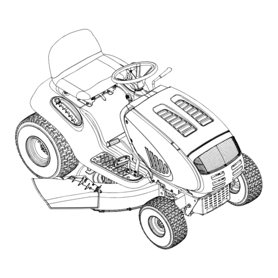
Model 609 Shown
IMPORTANT: READ SAFETY RULES AND INSTRUCTIONS CAREFULLY
Warning:
This unit is equipped with an internal combustion engine and should not be used on or near any unimproved forest-covered,
brush-covered or grass-covered land unless the engine's exhaust system is equipped with a spark arrester meeting applicable local or
state laws (if any). If a spark arrester is used, it should be maintained in effective working order by the operator. In the State of California
the above is required by law (Section 4442 of the California Public Resources Code). Other states may have similar laws. Federal laws
apply on federal lands. A spark arrester for the muffler is available through your nearest engine authorized service dealer or contact the
service department, P.O. Box 368022 Cleveland, Ohio 44136-9722.
MTD PRODUCTS INC. P.O. BOX 368022 CLEVELAND, OHIO 44136-9722
PRINTED IN U.S.A.
Operator's Manual
Automatic Lawn Tractor
Models 607
608
609
FORM NO. 770-10131B.fm
(11/2000)
Advertisement
Table of Contents

Related Manuals for MTD YARD MACHINES 607


Summary of Contents for MTD YARD MACHINES 607
- Page 1 A spark arrester for the muffler is available through your nearest engine authorized service dealer or contact the service department, P.O. Box 368022 Cleveland, Ohio 44136-9722. MTD PRODUCTS INC. P.O. BOX 368022 CLEVELAND, OHIO 44136-9722 FORM NO. 770-10131B.fm PRINTED IN U.S.A.
-
Page 2: Table Of Contents
(Model Number) (Serial Number) Copy the model number here: Copy the serial number here: MTD PRODUCTS INC CLEVELAND, OHIO 44136 CALLING CUSTOMER SUPPORT If you have difficulty assembling this product or have any questions regarding the controls, operation or maintenance of this unit, please call the Customer Support Department. -
Page 3: Important Safe Operation Practices
SECTION 1: IMPORTANT SAFE OPERATION PRACTICES WARNING: This symbol points out important safety instructions which, if not followed, could endanger the personal safety and/or property of yourself and others. Read and follow all instructions in this manual before attempting to operate this machine. Failure to comply with these instructions may result in personal injury. - Page 4 Contact an speeding may cause the operator to lose control of authorized MTD Service Dealer for assistance. the machine resulting in serious injury or death. 7. Do not tow heavy pull behind attachments (e.g.
- Page 5 Gasoline is frame, your unit should be serviced professionally extremely flammable and the vapors are explosive. by an authorized MTD Service Dealer. Serious personal injury can occur when gasoline is 4. Check brake operation frequently as it is subjected spilled on yourself or your clothes which can ignite.
- Page 6 8. Never tamper with the safety interlock system or For safety protection, frequently check components other safety devices. Check their proper operation and replace immediately with original equipment regularly. manufacturer’s (O.E.M.) parts only, listed in this 9. After striking a foreign object, stop the engine, manual.
-
Page 7: Slope Gauge
SECTION 2: SLOPE GAUGE... -
Page 8: Tractor Set-Up
SECTION 3: TRACTOR SET-UP Attaching the Battery Cables Service the engine with gasoline and oil as instructed in the separate Briggs & Stratton Operator/Owner Manual (or Kohler engine’s Owner’s Manual) packed with your NOTE: The positive battery terminal is marked Pos. tractor. -
Page 9: Know Your Lawn Tractor
SECTION 4: KNOW YOUR LAWN TRACTOR NOTE: Steering Wheel not shown for clarity. † Style varies by model ‡ If so equipped PTO (Power Take-off) Lever‡ G Throttle Control Lever PTO (Power Take-off) Knob‡ Cruise Control Button‡ Choke Control‡ Ignition Switch Parking Brake Button Brake Pedal Shift Lever... - Page 10 Throttle Control Lever Ignition Switch The throttle control lever is located on the right side of Never leave running WARNING: the tractor’s dash panel. This lever controls the speed machine unattended. Always disengage PTO, of the engine and, on some models, when pushed all move shift lever into neutral position, set the way forward, the choke control also.
- Page 11 Systems Indicator Monitor Electric PTO (Power Take-off) Knob Your tractor is equipped with either an hour meter or an ammeter as part of two available systems indicator To engage the power to the monitors. Locate the monitor on the left side of your cutting deck or other (separately dash panel and compare it to both shown in Figure 5.
-
Page 12: Operating Your Lawn Tractor
(ON) position with the shift lever in position for Contact an authorized MTD service dealer. The safety reverse travel. interlock system prevents the engine from cranking or •... - Page 13 • Turn the ignition key clockwise to the START WARNING position. After the engine starts, release the key. It will return to the ON position. AVOID SERIOUS INJURY OR DEATH Do NOT hold the key in the START IMPORTANT: position for longer than ten seconds at a time. Doing so •...
- Page 14 Engaging the Parking Brake NOTE: Cruise control can not be engaged at the tractor’s fastest ground speed. If the operator should To engage the parking brake: attempt to do so, the tractor will automatically • Fully depress the brake pedal and hold it down with decelerate to the fastest optimal mowing ground speed.
- Page 15 NOTE: It is not necessary to remove the discharge This tractor is equipped with one of MTD’s high quality chute to operate the mower with the mulch kit installed. cutting decks. The following information will be helpful when using the cutting deck with your tractor.
-
Page 16: Making Adjustments
SECTION 6: MAKING ADJUSTMENTS Never attempt to make any WARNING: • Loosen the two jam nuts on the rear side of the adjustments while the engine is running, deck stabilizer bracket. See Figure 9A. • Locate the two lock nuts on the opposite side of the except where specified in the operator’s manual. - Page 17 Parking Brake Adjustment Standard Seat To adjust the position of the seat on models not WARNING: Never attempt to adjust the equipped with a seat adjustment lever, loosen, but do NOT remove the four screws which secure the seat to brakes while the engine is running.
-
Page 18: Maintaining Your Lawn Tractor
• Remove the hex nut and lock washer on the top of • Place the steering wheel in position for straight ball joint. See Figure 12. ahead travel. • Thread the ball joint toward the jam nut to shorten • In front of the axle, measure the distance the drag link. -
Page 19: Service
Lubrication Front Axles Each end of the tractor’s front pivot bar may be WARNING: Before lubricating, repairing, or equipped with a grease fitting. Lubricate with a grease gun after every 25 hours of tractor operation. inspecting, always disengage PTO, move shift lever into neutral position, set parking Cleaning the Engine And Deck brake, stop engine and remove key to prevent... - Page 20 Cutting Blades Blade Separation Be sure to shut the engine off, WARNING: remove ignition key, disconnect the spark plug wire(s) and ground against the engine to prevent unintended starting before removing the cutting blade(s) for sharpening or replacement. Protect your hands by using Worn Blade Edge heavy gloves or a rag to grasp the cutting Wind Wing...
- Page 21 Changing the Deck Belt & PTO Belt • Lower the deck by moving the deck lift lever into the bottom notch on the right fender. • Remove the belt guards by removing the self- WARNING: Be sure to shut the engine off, tapping screws that fasten them to the deck.
- Page 22 Battery Tray Variable-speed Drive belt (Lower) Shift Lever Opening Pulley Rear Idler Pulley Drive belt (Upper) Belt Keeper Front Idler Pulley Idler Bracket Keeper Pins to drive pedal Double-Idler Bracket Engine Pulley Transmission Idler Pulley Single-speed Transmission Pulley Transmission Front of Tractor NOTE: View shown from above tractor.
- Page 23 Read through the following procedure prior to attempting it to determine if you feel you could successfully complete it. Hole If you don’t, see an authorized MTD service dealer to Idler Adjuster Rod have the belt changed.
-
Page 24: Off-Season Storage
SECTION 10: ATTACHMENTS & ACCESSORIES The following attachments and accessories are compatible for Lawn Tractor Models 607, 608 & 609. See the retailer from which you purchased your tractor, an authorized MTD Service Dealer or phone (800) 800-7310 for information regarding price and availability. -
Page 25: Troubleshooting
SECTION 11: TROUBLESHOOTING Trouble Possible Cause(s) Corrective Action Engine fails to start PTO engaged. Place PTO knob (or lever) in disengaged (OFF) position. Parking brake not engaged. Engage parking brake. Spark plug wire(s) disconnected. Connect wire(s) to spark plug(s). Throttle control lever not in correct Place throttle lever to FAST position. -
Page 26: Models 607, 608 & 609 Parts List
SECTION 12: MODELS 607, 608 & 609 PARTS LIST B&S OHV V-Twin B&S Opposed Twin (for throttle) (for starter cable) (for choke) (deflector must face forward) B&S OHV Single Kohler... - Page 27 Models 607, 608 & 609 REF. PART DESCRIPTION 710-0148 Self-tapping Screw, #8-32 x .375 710-0599 Self-tapping Screw, 1/4-20 x .5 710-0604A Self-tapping Screw, 5/16-18 x .625 710-1237 Screw, #10-32 x .625 (B&S OHV V-Twin) 710-1314 Socket Cap Screw, 5/16-18 x .625 710-1315 Self-tapping Screw, 3/8-16 x 1.25 712-3017...
- Page 28 Models 607 & 608...
- Page 29 Models 607 & 608 REF. PART REF. PART DESCRIPTION DESCRIPTION 683-0195 Bracket Assembly (8-style) 749-1087A Dash Support Tube 710-0599 Self-tapping Screw, 1/4-20 x .5 747-1184 Hood Plenum Support Rod 710-0751 Hex Cap Screw, 1/4-20 x .62 731-2247A Hood Plenum 710-0924 Phillips Pan Screw, 1/4-20 x .75 (Models with B&S OHV V-Twin) 710-1017...
- Page 30 Model 609...
- Page 31 Model 609 REF. PART REF. PART DESCRIPTION DESCRIPTION 783-1346 Grill Support Bracket (9-style) 710-3217 Truss Phillips Screw, #8-32 x .375 710-0599 Self-tapping Screw, 1/4-20 x .5 712-0142 Hex Nut, #8-32 710-0528 Hex Cap Screw, 5/16-18 x 1.25 731-1857 Throttle Control Knob 710-0924 Phillips Pan Screw, 1/4-20 x .75 731-2225...
- Page 32 Models 607, 608 & 609 Models w/ Quick-adjust Seat Models w/ Manually Adjusting Seat...
- Page 33 Models 607, 608 & 609 REF. PART REF. PART DESCRIPTION DESCRIPTION 747-1130A Deck Stabilizer Rod 783-0685B Fender, 4-Style† (Shown) 683-0197 Lift Shaft Assembly 783-0839A Fender, 7-Style‡ 711-0332 Clevis Pin, .5 x .78 783-0715A Seat Mounting Bracket 712-0206 Hex Nut, 1/2-13 710-1268 Screw, #10-16 x .375 712-0431...
- Page 34 Models 607, 608 & 609...
- Page 35 Models 607, 608 & 609 REF. PART REF. PART DESCRIPTION DESCRIPTION 710-0604A Self-tapping Screw, 16-18 x .625 736-0162 Flat Washer, .64 x 1.0 x .12 783-0726A RH Pivot Support Bracket 736-0187 Flat Washer, .64 x 1.24 x .06† 783-0727 LH Pivot Support Bracket 736-0316 Flat Washer, .78 x 1.589 x .06‡...
- Page 36 Models 607, 608 & 609 For a proper IMPORTANT: working machine, use Factory Approved Parts. V-belts are designed to engage and disengage safely. A substitute (non OEM) V-belt can be dangerous by not disengaging completely.
- Page 37 Model 607, 608 & 609 REF. PART REF. PART DESCRIPTION DESCRIPTION 783-1015 Shift Lever Support 783-0667B Transmission Torque Bracket 17840 Transaxle Mounting Bracket 783-0669 Idler Bracket 618-0551 Single-speed Transmission Assembly 736-0430 Flat Washer, .350 x 1.59 x .062 631-0009A Shifter Knob 647-0031 Brake Control Assembly 647-0045...
- Page 38 Model 607, 608 & 609...
- Page 39 Input Shaft 716-0108 Retaining Ring, .437 717-1464 14-tooth Bevel Pinion 719-0391A Upper Housing 736-0723 Thrust Washer, .635 x 1.25 x .042 *Use applicable flat washer (12a, 12b or 12c) in this application allowing proper end-play as instructed in MTD’s Service Manual.
- Page 40 Models 607, 608 & 609 (w/ Electric PTO) 46-inch 42-inch Deck Deck...
- Page 41 Models 607, 608 & 609 REF. PART REF. PART DESCRIPTION DESCRIPTION 783-0653D Steering Support Bracket 683-0450 Engagement Plate Assembly 683-0314 Frame Assembly 710-0520 Hex Cap Screw, 3/8-16 x 1.5 717-1708 Electric PTO Clutch 710-0831 Hex Cap Screw, 3/8-16 x 5.5 754-0497 PTO Belt (Models w/ 42-inch deck) 710-1238...
- Page 42 Models 607, 608 & 609 (w/ Manual PTO) 46-inch 42-inch Deck Deck † † Refer to D on page 46. * Refer to B on page 44.
- Page 43 Models 607, 608 & 609 REF. PART REF. PART DESCRIPTION DESCRIPTION 723-0444 Battery Strap 647-0046A PTO Engage Lever Assembly 683-0450 PTO Engage Plate Assembly 738-1020 Shoulder Screw, .625 x .5, 7/16-20 710-0276 Carriage Screw, 5/16-18 x 1.00 736-0407 Bell Washer, .45 x 1.0 x .062 712-0459 Flange Lock Nut, 7/16-20 710-0520...
- Page 44 Models 607, 608 & 609 † ‡ ‡ ‡ ‡ † ‡ ‡ ‡ ‡ ‡ † * Refer to B on page 42. † Found on models equipped with an electric PTO only. ‡ Found on models equipped with a manual PTO only.
- Page 45 Models 607, 608 & 609 REF. PART REF. PART DESCRIPTION DESCRIPTION 736-0119 Lock Washer, 5/16 16606 Retainer Hook 618-0565 Spindle Assembly, 5.75 Dia. 736-0158 Lock Washer, 5/8 756-0980 Pulley Only 736-0162 Flat Washer, .64 x 1.0 x .12 736-0270 Bell Washer, .265 x .75 x .062 683-0198D 42-inch Deck Shell 683-0254...
- Page 46 Models 607, 608 & 609 ‡ ‡ † ‡ ‡ ‡ ‡ ‡ ‡ ‡ ‡ 46-inch Deck Brake Assembly † Refer to D on page 42. ‡ Found on models equipped with a manual PTO only. * A single-pulley spindle (618-0240A) is found in this location on models with a manual PTO.
- Page 47 Models 607, 608 & 609 REF. PART REF. PART DESCRIPTION DESCRIPTION 736-0119 Lock Washer, 5/16 16606 Retainer Hook 736-0270 Bell Washer, .265 x .75 x .062 17982 Spindle Reinforcement Plate 738-0347 Shoulder Spacer, .625 x 1.16 618-0240A Spindle Assembly, 5.0 Dia. 738-0373 Shoulder Screw 756-1187...
- Page 48 MANUFACTURER’S LIMITED WARRANTY FOR: c. Routine maintenance items such as lubricants, filters, The limited warranty set forth below is given by MTD blade sharpening and tune-ups, or adjustments such PRODUCTS INC (“MTD”) with respect to new merchandise as brake adjustments, clutch adjustments or deck purchased and used in the United States, its possessions adjustments;...