
Related Manuals for Ariston COMPACT M NET R32


Summary of Contents for Ariston COMPACT M NET R32
- Page 1 COMPACT M NET R32 3301721 3301722 3301723 3301724 TECHNICAL INSTRUCTIONS FOR INSTALLATION AND MAINTENANCE 420000590201...
- Page 2 This manual was drawn up with the aim of informing you on – RoHS 3 2015/863/EU on restrictions regarding the use how to install, use and maintain the COMPACT M NET R32 sys- of certain hazardous substances in electrical and elec- tem, in order to enable you to optimally use all the functions.
-
Page 3: Table Of Contents
Contents 1. Safety advices 5. Electrical connections 1.1 General warnings and safety instructions 5.1 Outdoor unit electrical connections 1.2 Use of the R32 refrigerant 5.2 Indoor unit electrical connections 1.3 Symbols affixed to the appliance 5.3 Example of electrical connection between indoor and outdoor units 2. -
Page 4: Safety Advices
General warnings and safety instructions presence of other gases or substances in the unit can reduce its performances and relia- This manual is the property of ARISTON and it bility, and also cause an abnormal pressure is forbidden to reproduce or transfer to third increase during the cooling cycle. -
Page 5: Use Of The R32 Refrigerant
Safety advices Use of the R32 refrigerant During all work procedures, wear individual protective clothing and equipment. Do not touch the installed product if barefoot and/ FLAMMABLE MATERIAL or with any wet part of the body. Reset all safety and control functions affected The R32 refrigerant is odourless. -
Page 6: Symbols Affixed To The Appliance
Safety advices Symbols affixed to the appliance Indoor unit The appliance has the following symbols affixed to it: Outdoor unit Fig. 1 Reference Description Danger moving parts Danger flammable refrigerant Normative symbols for R32 gas Serial number Fig. 2 000000000000 Electrical precautions Reference Description... -
Page 7: Description Of The System
Description of the system 2. Description of the system Composition of the system The COMPACT M NET R32 system is made up of: – An indoor unit – An outdoor unit – An outdoor temperature sensor – Master User Interface –... -
Page 8: Outdoor Unit
Description of the system Outdoor unit 2.1.1 Structure The outdoor unit supplied is one of the following models: – NIMBUS 35 M EXT R32 – NIMBUS 50 M EXT R32 – NIMBUS 80 M EXT R32 – NIMBUS 80 M-T EXT R32 –... -
Page 9: Dimensions And Weights
Description of the system 2.1.2 Dimensions and weights 120 M & M-T 150 M & M-T Outdoor unit Weight [kg] 1016 mm 374 mm NIMBUS EXT R32 35 M - 50 M NIMBUS EXT R32 80 M NIMBUS EXT R32 80 M-T NIMBUS EXT R32 120 M - 150 M NIMBUS EXT R32 120 M-T - 150 M-T 35 M - 50 M... -
Page 10: Hydraulic Fittings
Description of the system 2.1.3 Hydraulic fittings 89 mm 71 mm G 1”F G 1”F Fig. 8 Fig. 9 Plumbing connections Electrical connections passage 2.1.4 Accessories The outdoor unit can be equipped with the following acces- sories: – anti-freeze kit –... -
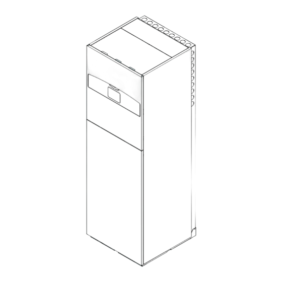
Page 11: Indoor Unit
Description of the system Indoor unit 2.2.1 Structure The indoor unit supplied is one of the following models: – NIMBUS FS M R32 – NIMBUS FS M 2Z R32 – NIMBUS FS-L M R32 – NIMBUS FS-L M 2Z R32 General structure Fig. - Page 12 Description of the system Structure of the hydraulic part Mod. 1Z Mod. 2Z Fig. 11 Space heating flow Zone 1 circulation pump Motor-driven three-way valve Zone 2 circulation pump Separator flow Zone controller Automatic deaerator Motor-driven mixing valve 10 Hydraulic separator Non-return valve 12 / EN...
-
Page 13: Dimensions And Weights
Description of the system 2.2.2 Dimensions and weights Return to heat pump Indoor unit Weight [kg] DHW recirculation NIMBUS FS M R32 Domestic hot water inlet NIMBUS FS M 2Z R32 NIMBUS FS-L M R32 NIMBUS FS-L M 2Z R32 Domestic hot water flow System return Delivery from heat pump... - Page 14 Description of the system 2-ZONE configuration Fig. 16 Fig. 17 Label Description Ø of 552 mm fittings 435 mm [inches] 360 mm Zone 1 system flow 300 mm 240 mm 211 mm Zone 2 system flow 130 mm Zone 1 system return Zone 2 system return Safety valve drain Return to heat pump...
-
Page 15: Operational Limits
Description of the system Operational limits 2.3.1 Compressor frequency table The maximum allowed frequency varies with the outdoor tem- The following diagrams show the limits of the heat pump. The perature. temperature difference between the delivery and return of the The values shown in the table refer to the following conditions: plate heat exchanger must be between 5°C and 8°C. -
Page 16: System Interface Sensys Hd
Time and date SALOTTO Operation icons °C 1,5 bar Pressure indication The SENSYS HD interface is compatible with Ariston NET when used with an ARISTON Wi-Fi module. Find out more on www.ariston.com/it/ ariston-net Fig. 23 SYMBOLS SYMBOLS Wi-Fi module update in progress... -
Page 17: Technical Data
– Connect the wire to the terminal (C) by introducing it space heating from the lower part after creating a suitable passage. In a system with 3 zones with 2 ARISTON room Sensors: – Place the sensor cover back in the correct position. Temperature control class... -
Page 18: Installation
Installation 3. Installation – Ensure that all applicable national safety standards are observed throughout the course of the installation. – Ensure that the system is adequately earthed. Preliminary warnings – Check that the power supply voltage and frequency match those required by the outdoor unit, and that the The appliance must be installed exclusively by installed power is sufficient for its operation. -
Page 19: Receiving The Product
Upon receiving the product, make sure that its contents are intact and complete and, if they do The COMPACT M NET R32 system is supplied in multiple items not match the order, contact the branch that sold protected by a cardboard pack: the appliance. -
Page 20: Noise Level
Installation Minimum installation distances 3.3.2 Noise level To limit noise pollution and the transmission of vibrations: – Install the outdoor unit on a metal frame or on a vibra- tion-damping base. Vibration dampers must be mount- ed to reduce the transmission of vibrations. –... -
Page 21: Installation
Installation 3.3.4 Installation The outdoor unit must be anchored to the floor or to a wall-mounted bracket. Before installing the system, check that its sup- porting base is sufficiently resistant and level. Arrange the unit’s installation base according to the dimen- sions shown below. -
Page 22: Arranging The Connections
Installation 3.3.5 Arranging the connections 3.3.6 Installing the accessory kit Anti-freeze kit – To allow the passage of cables, use a screwdriver to re- move the pre-cut pieces (1) from the unit’s frame. – To detach the pre-cut pieces effectively, keep the unit’s front panel fitted on. -
Page 23: Installing The Indoor Unit
Installation Installing the indoor unit – To ensure correct operation of the kit, the unit must rest on a base measuring at least 70 mm. 3.4.1 Place of installation The indoor unit must be positioned in an occupied room to ensure best performances. -
Page 24: Handling
Installation 3.4.2 Handling Once the packaging has been removed, the indoor unit can be handled with suitable equipment (pallet truck or forklift truck). Handling operations may potentially cause per- sonal injuries or damages to the appliance or to the surrounding area. Identify the risky area and check that it is free of people or objects during lifting operations. -
Page 25: Hydraulic Connections
Hydraulic connections 4. Hydraulic connections Indoor unit hydraulic connections Preliminary checks: – check that the system has been cleaned; – check that there are no impurities in the circuit water; – check that compatible components are used (e.g. do not connect copper and steel to each other); –... -
Page 26: Safety Valve Drain
Hydraulic connections 4.1.2 Minimum water content Make the following hydraulic connections: – Zone 1 system flow (1) The system must be sized for a minimum water con- – Zone 2 system flow (2) tent of at least 5 litres for every kW of rated power. –... -
Page 27: Available Pressure
Hydraulic connections 4.1.5 Available pressure Indoor unit head loss Make sure that the available pressure is not lower than the head loss of the entire hydraulic system. The curves in the pictures below shown the available pressure on the flow from the outdoor unit. NIMBUS 35 M EXT R32 - NIMBUS 50 M EXT R32 1000 1500... -
Page 28: Characteristics Of The Supply Water
Hydraulic connections 4.1.6 Characteristics of the supply water 1-ZONE configuration Make sure that the system is supplied with water having a hard- ness between 8°F and 15°F and conductivity below 500 μS/cm. In zones where the water is particularly hard, mount a water softener. -
Page 29: Schematic Hydraulic Diagram
Hydraulic connections Schematic hydraulic diagram 1 ZONE FS Fig. 54 Outdoor unit Symbol Description Indoor unit System flow Sensys interface System return Shutter valve Sludge filter Communication connection System expansion vessel Electrical connection Bypass (optional) Outdoor Sensor Domestic cold water inlet 3-way valve Domestic hot water outlet 10 Siphon... - Page 30 Hydraulic connections 2 ZONES FS Fig. 55 Outdoor unit Symbol Description Indoor unit System flow Sensys interface System return Shutter valve Sludge filter Communication connection System expansion vessel Electrical connection Bypass (optional) Outdoor Sensor Domestic cold water inlet 3-way valve Domestic hot water outlet 10 Siphon 11 Non-return valve...
-
Page 31: Electrical Connections
Electrical connections 5. Electrical connections – The manufacturer is not liable for any damage caused by a system with inadequate earthing or electrical sys- tem anomalies. Carry out the electrical connections after having – Connect the power supply cable to a 230 V- 50 Hz (1 completed all the hydraulic connections. - Page 32 Electrical connections The cross-sectional size of the cables used must comply with the system power (see data plate). The cross-sectional size of the power cables indicated in the table must be regarded as the minimum cross-sectional -size. Prior to accessing the terminals, all the supply circuits must be disconnected. OUTDOOR UNIT NIMBUS EXT R32 35 M...
-
Page 33: Outdoor Unit Electrical Connections
Electrical connections Outdoor unit electrical connections 1-ph outdoor unit terminal board In accordance with the installation instructions, all systems for disconnecting the main power supply must have an open contact (4 mm) that guarantees full disconnection as per the indications of the Class III overvoltage conditions. Make the earth connection before proceeding ⏚... - Page 34 Electrical connections The ST1 connection is bridged by default. Do not remove the jumper. If the installation involves the use of thermostats or timer-controlled thermostats to manage the heat request, it is necessary to ensure that they do not have a proportional-band control logic. This logic may indeed cause inefficient behaviour of the system and fail to guarantee the fulfilment of the room temperature set-point.
-
Page 35: Indoor Unit Electrical Connections
Electrical connections Indoor unit electrical connections – Detach the clips (4) and open the cover (5). Before carrying out any work on the system, shut off the power supply at the main switch. Comply with the neutral and phase connections. –... - Page 36 Electrical connections – Remove the shaped plugs (9) for passing cables (10), Power supply connections (12) and (13). – Pass the power cable (10) through the cable grommet (11). – Pass the load power cables (12) and (13) through the cable grommets (14) and (15).
- Page 37 Electrical connections The cross-section and length of the cables must be sized ac- Power terminal board cording to the power indicated on the indoor unit’s data plate. Once you have completed the connections be- tween the indoor and outdoor units, put both electrical panels back into place.
-
Page 38: Example Of Electrical Connection Between Indoor And Outdoor Units
Electrical connections Example of electrical connection between indoor and outdoor units Before carrying out any work on the system, shut off the power supply at the main switch. The electrical connection between the indoor and outdoor units must be made using the two low-voltage terminal boards: G and Connect “G”... -
Page 39: Outdoor Unit Overview
Electrical connections Outdoor unit overview Mod. NIMBUS 35 M EXT R32 - NIMBUS 50 M EXT R32 ... - Page 40 Electrical connections Mod. NIMBUS 80 M EXT R32 (1ph) ...
- Page 41 Electrical connections Mod. NIMBUS 80 M-T EXT R32 (3ph) ...
- Page 42 Electrical connections Mod. NIMBUS 120 M EXT R32 - NIMBUS 150 M EXT R32 (1ph) ...
- Page 43 Electrical connections Mod. NIMBUS 120 M-T EXT R32 - NIMBUS 150 M-T EXT R32 (3ph) ...
-
Page 44: Indoor Unit Overview
Electrical connections Indoor unit overview ... -
Page 45: Installing The System Interface
Electrical connections Installing the system interface – Position the system interface on the base, pushing it slightly downwards. Note: when installing cascade systems, to install the system interface refer to the relevant dedicated manual. Positioning The system interface detects the room temperature. This factor must be taken into account when choosing its position. - Page 46 Electrical connections – Pass the BUS cable (5) through the hole (6) on the elec- – Open the flap (9) of the housing and insert the inter- trical panel. face (10). Fig. 84 Fig. 86 – Open the internal panel (7) to access the housing (8) –...
-
Page 47: Installing The Light Gateway
Electrical connections Installing the Light Gateway Signal sending, receiving, and decoding is carried out using BUS protocol, which ensures the interaction between the sys- Note: when installing cascade systems, to install the Light tem and the interface. Gateway interface refer to the relevant dedicated manual. Connect the cables to the terminal board located in the sys- tem’s indoor unit panel. - Page 48 Electrical connections – Position the Light Gateway (5) in the housing (4) and – Pass the BUS cable (8) through the hole (9) on the elec- close the panel (3). trical panel. Fig. 91 Fig. 93 – Detach the clips (2) and open the cover (3). –...
-
Page 49: Commissioning
Commissioning 6. Commissioning Preliminary checks OUTDOOR UNIT – The unit must be positioned on a sturdy and perfectly Checking for electrical dispersions and gas horizontal base, in a place that is easily accessible for leakages subsequent maintenance operations. – If there are significant air draughts, a protective screen 6.1.1 Electrical safety checks must be fitted. -
Page 50: Initial Start-Up
Commissioning HYDRAULIC CONNECTIONS Initial start-up – The water supply distribution network pressure must To guarantee safety and correct operation of the never exceeds 5 bar, otherwise a pressure reducer must system interface, it must be commissioned by a be installed on the system’s intake. qualified technician in possession of the skills as –... -
Page 51: Basic Functions
Commissioning Basic functions Room temperature adjustment with AUTO function on If the heating hot water temperature does not match the de- The system interface is a device that controls the heating sys- sired value, it can be increased or decreased via the “Heating tem. -
Page 52: Technical Parameters
Commissioning Technical parameters INPUT OUTPUT CONFIGURATION 1.1.0 HV IN 1 (input configurable to 230 V) Simultaneously press the “Esc” and “Menu” buttons until “Insert Press the selector . Turn the selector to choose the de- Code” appears on the display. sired item. - Page 53 Commissioning 1.1.3 AUX input 1 1.1.5 Electric heat sources blocking type Press the selector . Turn the selector to choose the de- Press the selector . Turn the selector to choose the de- sired item. sired item. None. None. The company block function is not specified. Humidity sensor: when the contact is closed, the heat Soft lockout.
- Page 54 Commissioning 1.2.2 AUX 3 output 1.2.6 Pro-Tech anode active None. Indicates the presence of the impressed-current anode on the Error alarm: the contact is closed in case of a system er- DHW calorifier. ror. Humidistat alarm: the contact is closed when the AUX1 CH SECONDARY HEAT SOURCE ACTIVATION input is set as a humidistat and the contact is closed.
- Page 55 Commissioning 1.4.2 Delay timer Press the selector . Turn the selector to choose the de- Time required for starting the calculation of the DHW integra- sired item. tion with the auxiliary sources or with the heating elements. WATER CIRCULATION 1.4.3 Release integral threshold 1.6.0 CH pump prerun time Activation threshold for DHW integration expressed in °C x min.
- Page 56 Commissioning 1.9.8 Thermal Cleanse Cycle frequency Press the selector . Turn the selector to choose the de- Sets the period of time after which the DHW calorifier sanitisa- sired item. tion function is repeated. DOMESTIC HOT WATER Press the selector .
- Page 57 Commissioning 1.12.5 Floor drying cycle Ready to Use + Functional (heating of the screed at a Defines the screed drying programme for under-floor systems variable temperature from 25°C to the temperature de- using the following values: fined by Par. 1.12.6, according to the period indicated as an example in the graph for an 18-day period, then at Functional (screed heating at a fixed temperature of a fixed temperature of 25°C for a period of 3 days, then...
-
Page 58: Temperature Adjustment
Commissioning Temperature adjustment 4.2.2 Slope Press the selector . Turn the selector and set the curve in Simultaneously press the “Esc” and “Menu” buttons until “Insert accordance with the type of heating system. Code” appears on the display. Press the selector to confirm. - Page 59 Commissioning 4.2.3 Parallel shifting COOLING 4.5.0 Z1 Cooling T Set Press the selector . Turn the selector and set the most suita- Press the selector . Turn the selector and set the delivery set- ble value. Press the selector to confirm. point temperature value, if temperature control is deactivated IMPORTANT: or with fixed point.
-
Page 60: Standard Sg Ready
Commissioning Under-floor system 4.5.4 Parallel shifting Turn the selector then set the most suitable value and °C press the selector to confirm. 4.5.6 Maximum delivery temperature Turn the selector then set the most suitable value and press the selector to confirm. 4.5.7 Minimum delivery temperature Repeat the steps described previously to set the values for zone 2 (where present), by selecting menu 5. -
Page 61: Parameter Table
Commissioning Parameter table Menu. Sub-menu. Description Default Range - Value Notes Parameter Energy Manager Basic parameters 0 = None 1 = Hybrid Mode 0 IDU type 2 = Hydraulic module 3 = Light 0 = None 1 External Unit Version 1 = Heat Pump 0 = None 2 Tank management... - Page 62 Commissioning Menu. Sub-menu. Description Default Range - Value Notes Parameter 0 = All zones 1 = Zone 1 2 = Zone 2 3 = Zone 3 4 = Zone 4 5 = Zone 5 9 Humidity input zone 6 = Zone 6 7 = Zones 1 , 2 8 = Zones 3 , 4 9 = Zones 5 , 6...
- Page 63 Commissioning Menu. Sub-menu. Description Default Range - Value Notes Parameter CH secondary heat source activation 0 = Heat integr. and backup 0 CH aux heat source activation logic 1 = HP failure backup 1 Active resistance stages 0 = Eco Plus 1 = Eco 2 ECO / COMFORT 2 = Average...
- Page 64 Commissioning Menu. Sub-menu. Description Default Range - Value Notes Parameter 0 = Disabled 2 Comfort Function 1 = Time Based 2 = Always active 0 = Standard 1 = GREEN 3 DHW operation mode 2 = HC - HP 3 = HC - HP 40 5 Max HP charging time 120 min [30-240]min...
- Page 65 Commissioning Menu. Sub-menu. Description Default Range - Value Notes Parameter 6 Floor drying Flow Set Point T 55°C [25-60]°C 7 Floor drying total Remaining Days 8 Dhw rating mode 0 = OFF 9 Exogel kit activation 1 = ON Energy Manager Statistics 1 Heating running hours (h/10) 2 DHW running hours (h/10) 3 Resistor 1 running hours (h/10)
- Page 66 Commissioning Menu. Sub-menu. Description Default Range - Value Notes Parameter EM diagnostics - 2 input 0 = OFF 0 Room Thermostat 1 1 = ON 0 = OFF 1 Room Thermostat 2 1 = ON 0 = Open 2 AUX input 1 1 = Close 0 = Open 3 AUX input 2...
- Page 67 Commissioning Menu. Sub-menu. Description Default Range - Value Notes Parameter Zone 1 parameters Setpoint 19°C Heat - 24°C 0 T Day 10-30°C Cool 13°C Heat - 30°C 1 T Night 10-30°C Cool 2 T set Z1 40 [HT] - 20 [LT] par 4.2.5 - par 4.2.6 3 Zone frost temperature 5°C...
- Page 68 Commissioning Menu. Sub-menu. Description Default Range - Value Notes Parameter Visible only 2 Pump fixed speed 20-100 with Zone Module Cool mode 0 T Set Cool 0 = Fan Coil[FC] 1 Cooling Temp Range 1 = Underfloor[UFHC] 0 = ON/OFF Thermostat 2 Thermoregulation 1 = Fix Flow T 2 = Outdoor T Only...
- Page 69 Commissioning Menu. Sub-menu. Description Default Range - Value Notes Parameter 13°C Heat - 30°C 1 T Night 10-30°C Cool 2 T set Z2 40 HT - 20 LT par 425-426 3 Zone frost temperature 5°C 2-15°C Automatic winter mode 0 = OFF 0 Automatic winter mode activation 1 = ON 1 Automatic winter mode threshold...
- Page 70 Commissioning Menu. Sub-menu. Description Default Range - Value Notes Parameter 0 = ON/OFF Thermostat 2 Thermoregulation 1 = Fix Flow T 2 = Outdoor T Only 3 Slope 25 [FC] or 20 [UFH] 18-33 [FC] or 0-60 [UFH] 4 Paral shift 0°C (-2.5 –...
- Page 71 Commissioning Menu. Sub-menu. Description Default Range - Value Notes Parameter 0 = OFF 3 Z3 Pump control 1 = ON 0 = OFF 4 Z2 Mix Valve Control 1 = Open 2 = Close 0 = OFF 5 Z3 Mix Valve Control 1 = Open 2 = Close 0 = OFF...
- Page 72 Commissioning Menu. Sub-menu. Description Default Range - Value Notes Parameter Do you really want to perform the reset ? If you press OK button, the reset command will be executed otherwise, by way of ESC, the previous page is shown Heat Pump TDM Basic parameters Input configuration...
- Page 73 Commissioning Menu. Sub-menu. Description Default Range - Value Notes Parameter HP diagnostics - input 2 0 = OFF 1 = Standby 2 = Cool mode 3 = CH 4 = Booster Heating 5 = Booster Cooling 6 = Rating Heating Mode 7 = Rating Cooling Mode 8 = Frost Protection 9 = Defrost...
- Page 74 Commissioning Menu. Sub-menu. Description Default Range - Value Notes Parameter 13. 13 Error History 13. 13. 0 Last 10 errors 13. 13. 1 Reset error list Do you really want to perform the reset ? If you press OK button, the reset command 13.
- Page 75 Commissioning Menu. Sub-menu. Description Default Range - Value Notes Parameter Maximum Water temp 0 = Disabled 0 Control mode 1 = Time Based 2 = Always active 1 Reduced Setpoint heating 2 Reduced Setpoint cooling System settings 0 = Series 0 Buffer integration scheme 1 = Parallel 0 = NO...
-
Page 76: Service
Service 7. Service If there is a fault that could jeopardise safety, do not connect the power supply to the circuit un- Maintenance is an essential operation for safety, correct boiler til the problem has been adequately resolved. operation, and system durability. If the fault cannot be resolved immediately but It must be carried out in accordance with applicable regula- the device must nonetheless continue operat-... - Page 77 Service Checklist for annual maintenance To clean the filter a 3/4"-diameter hose is required for Check the following elements at least once a year: draining the water. Use an intermediate hose connec- tion to connect the hose. Proceed as follows: –...
- Page 78 Service – Automatic deaeration valve. – Safety valve (if installed). To check the condition of the discs, it is necessary to The safety valve is used to protect the storage tank and access the upper part of the valve and dismantle it. the heat exchanger for domestic hot water production If the disc appears to be damaged and/or has expanded against overpressure.
-
Page 79: Cleaning And Inspecting The Indoor Unit
Service Cleaning and inspecting the indoor unit User information Inform the user on how to operate the installed system. It is necessary to carry out the following checks at least once In particular, hand this instruction manual to the users, inform- a year: ing them that is must be kept near the product at all times. -
Page 80: Error List
Service Error list The errors are displayed on the interface in the indoor unit (see paragraph "System interface SENSYS HD"). Indoor unit errors Code Description Resolution Outside temperature not available Temperature control activation based on the external sensor External sensor not connected or damaged. Check the sensor’s connection and replace it, if necessary. - Page 81 Service Code Description Resolution Floor thermostat 1 error Check the flow of the under-floor system. Check the connection of the thermostat on the IN-AUX2 STE terminal of the Energy Manager and/or STT of the TDM. If the thermostat of the under-floor system is not present, apply an electrical jumper to terminal IN-AUX2 STE of the Energy Manager and/or STT of the TDM.
- Page 82 Service Outdoor unit errors Error Description NO RESET RESET Volatile User reset HP Power Service reset TD sensor error HP compressor mismatch error HP fan mismatch error HP 4-way valve mismatch error Expansion valve mismatch error HP zero fan speed Inverter-TDM communication error 4-way valve error LWT sensor error...
- Page 83 Service Inverter error Description Code (for inverter errors NIMBUS EXT R32 falling within error code 35 M - 50 M - 80 M-T - 120 120 M - 150 931) 80 M M-T - 150 Inverter output current sensor error DC bus condensers pre-charge error Inverter input voltage sensor error Inverter heat sink temperature sensor error...
-
Page 84: Decommissioning
Decommissioning 8. Decommissioning Draining the circuit and recovering the refrigerant Prior to performing this procedure, it is imperative for the tech- To correctly recover the refrigerant from the system, the follow- nician to fully understand the equipment and all its details. ing standard indications must be observed: We recommend recovering all the refrigerants safely. -
Page 85: Disposal
Decommissioning Disposal Professional WEEE: all WEEE other than that coming from households as mentioned above. The manufacturer is registered with the national EEE Register, This equipment may contain: in conformity to the implementation of Directive 2012/19/EU, – Refrigerant gas that must be fully recovered by special- and of the relative national regulations in force concerning ised personnel and accompanied by the necessary au- waste electrical and electronic equipment. -
Page 86: Technical Information
Technical information 9. Technical information Outdoor unit Data plate Indoor unit Fig. 108 Name or trademark Model Heating data Nominal heating performance Cooling data Nominal cooling performance Refrigeration circuit oil type Fig. 107 Refrigerant type - refrigerant filling GWP. Global Warming Potential index Model - Serial no. -
Page 87: Annexes
Annexes 10. Annexes 87 / EN... - Page 88 Viale Aristide Merloni, 45 60044 Fabriano (AN) Italy Telefono 0732 6011 Fax 0732 602331 www.ariston.com...