Advertisement
Box Contents
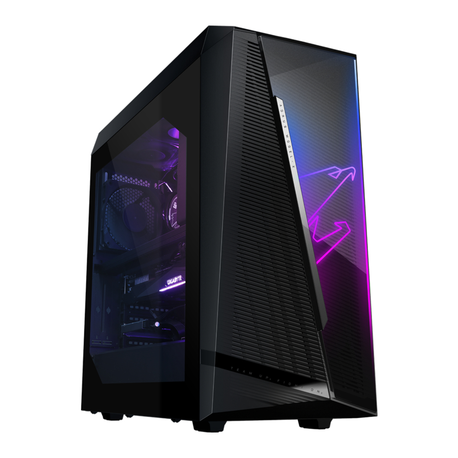
 AORUS MODEL X GAMING DESKTOP PC
Quick Start Guide
AC power cord
Antennas
2.5" drive screws
Two Mini-DisplayPort cables
* The box contents above are for reference only and the actual items shall depend on the product package you obtain. The box contents are subject to change without notice.
Optional Items
 Glass side panel
Hardware Setup
Safety Information
- Before connecting to the power outlet, make sure that the voltage rating of the power cable is compatible with the power specification in the country where you are located.
- The power cord plug must be connected to a properly wired and grounded power outlet.
- Be sure that the power outlet you plug the power cord into is easily accessible and located as close to the equipment operator as possible. When you need to disconnect power to the equipment, be sure to unplug the power cord from the electrical outlet.
![shock hazard]() Do not touch the plug with wet hands, otherwise easily cause electric shock.
Do not touch the plug with wet hands, otherwise easily cause electric shock.- Protect the power cord from being tread upon or pinched, particularly at the plug.
- To avoid damage of internal component, do not place the product on a vibrating surface.
- Operating temperature: 5~35°C
- Do not place the product near any heat sources such as electric radiators, heat registers, stoves or other devices (including amplifiers) that produce heat.
- The holes or openings on this product are for ventilation to ensure reliable operation of the product and to protect it from overheating. Do not cover or block the ventilation holes with any objects.
![burn hazard]()
![shock hazard]()
Never push objects of any kind into this product through cabinet slots as they may touch dangerous voltage points or short-out parts that could result in a fire or electric shock.- Never spill liquid of any kind onto or into the product.
![shock hazard]() Do not use this product near water, drinks, or all types of liquids. Do not expose this apparatus to rain, liquid or moisture. Failure to do so may result in electric shock or damage.
Do not use this product near water, drinks, or all types of liquids. Do not expose this apparatus to rain, liquid or moisture. Failure to do so may result in electric shock or damage.- This product is not water proof or oil-proof.
- Clean the equipment with a soft, dry cloth.
- The manufacturer specifies that the thumbscrews normally should be tightened with a screwdriver, use of thumbscrews is not considered to compromise the basic principles of safety associated with the Safety Standard.
- For the motherboard battery replacement, refer to the motherboard's User Manual.


System Overview

- Power Button
The power button allows users to turn on/off the computer. - USB 3.2 Gen 1 Port
The USB 3.2 Gen 1 port supports the USB 3.2 Gen 1 specification and is compatible to the USB 2.0 specification. Use this port for USB devices. - USB Type-C Port
The reversible USB port supports the USB 3.2 Gen 2x2 specification and is compatible to the USB 3.2 Gen 2, USB 3.2 Gen 1, and USB 2.0 specification. Use this port for USB devices. - Mic In
The Mic in jack. - Line Out
The line out jack.

- Q-Flash Plus Button (Note)
This button allows you to update the BIOS when the power connector is connected but the system is not powered on. - Clear CMOS Button
Use this button to clear the CMOS values (e.g. BIOS configuration) and reset the CMOS values to factory defaults when needed.

- Always turn off your computer and unplug the power cord from the power outlet before using the clear CMOS button.
- Do not use the clear CMOS button when the system is on, or the system may shutdown and data loss or damage may occur.
- After system restart, go to BIOS Setup to load factory defaults (select Load Optimized Defaults) or manually configure the BIOS settings (please navigate to the "BIOS Setup" page of GIGABYTE's website for more information).
- SMA Antenna Connectors (2T2R)
Use this connector to connect an antenna.
![information]() Tighten the antennas to the antenna connectors and then aim the antennas correctly for better signal reception.
Tighten the antennas to the antenna connectors and then aim the antennas correctly for better signal reception. - USB 3.2 Gen 1 Port
The USB 3.2 Gen 1 port supports the USB 3.2 Gen 1 specification and is compatible to the USB 2.0 specification. Use this port for USB devices. - USB 3.2 Gen 2 Type-A Port (Red)
The USB 3.2 Gen 2 port supports the USB 3.2 Gen 2 specification and is compatible to the USB 3.2 Gen 1 and USB 2.0 specification. Use this port for USB devices. - DisplayPort
DisplayPort delivers high quality digital imaging and audio, supporting bi-directional audio transmission. DisplayPort can support HDCP 2.3 content protection mechanisms. You can use this port to connect your DisplayPort-supported monitor. Note: The DisplayPort Technology can support a maximum resolution of 4096x2304@60 Hz but the actual resolutions supported depend on the monitor being used.
![information]() After installing the DisplayPort device, make sure to set the default sound playback device to DisplayPort. (The item name may differ depending on your operating system.)
After installing the DisplayPort device, make sure to set the default sound playback device to DisplayPort. (The item name may differ depending on your operating system.) - USB Type-C Port (with USB 3.2 Gen 2 Support)
The reversible USB port supports the USB 3.2 Gen 2 specification and is compatible to the USB 3.2 Gen 1 and USB 2.0 specification. Use this port for USB devices. - RJ-45 LAN Port
The Gigabit Ethernet LAN port provides Internet connection at up to 10 Gbps data rate. The following describes the states of the LAN port LEDs.
![]()

| Speed LED: | |
| State | Description |
| Green | 10 Gbps data rate |
| Orange | 5 Gbps/ 2.5 Gbps/ 1 Gbps/ 100 Mbps data rate |
| Activity LED: | |
| State | Description |
| Blinking | Data transmission or receiving is occurring |
| On | No data transmission or receiving is occurring |
- USB 3.2 Gen 2 Type-A Port (Q-Flash Plus Port)
The USB 3.2 Gen 2 port supports the USB 3.2 Gen 2 specification and is compatible to the USB 3.2 Gen 1 and USB 2.0 specification. Use this port for USB devices. Before using Q-Flash Plus (Note), make sure to insert the USB flash drive into this port first. - USB Type-C Port (with USB 3.2 Gen 2x2 Support)
The reversible USB port supports the USB 3.2 Gen 2x2 specification and is compatible to the USB 3.2 Gen 2, USB 3.2 Gen 1, and USB 2.0 specifications. Use this port for USB devices. - Center/Subwoofer Speaker Out
Use this audio jack to connect center/subwoofer speakers. - Rear Speaker Out
Use this audio jack to connect rear speakers. - Optical S/PDIF Out Connector
This connector provides digital audio out to an external audio system that supports digital optical audio. Before using this feature, ensure that your audio system provides an optical digital audio in connector. - Line In/Side Speaker Out
The line in jack. Use this audio jack for line in devices such as an optical drive, walkman, etc. - Line Out/Front Speaker Out
The line out jack. This jack supports audio amplifying function. For better sound quality, it is recommended that you connect your headphone/speaker to this jack (actual effects may vary by the device being used). - Mic In/Side Speaker Out
The Mic in jack.
| Audio Jack Configurations: | ||||
| Jack | Headphone/2-channel | 4-channel | 5.1-channel | 7.1-channel |
|  | | ||
| | | | |
| | |||
| | | | |
| | |||

- If you want to install a Side Speaker, you need to retask either the Line in or Mic in jack to be Side Speaker out through the audio driver.
- To enable or configure the audio amplifying function for the Line out jack, please access the Realtek Audio Console application.
(Note) To enable the Q-Flash Plus function, refer to "Using Q-Flash Plus" Chapter of the manual.

- DisplayPort
The connector supports DisplayPort 1.4a version. - HDMI Port
The connector supports HDMI 2.1 version. - DisplayPort
The connector supports DisplayPort 1.4 version, HDCP 2.2, and HDR. It can support a maximum resolution of 8K (7680x3840)@60 Hz. (Note 1) (Note 2) - Thunderbolt 4 Port
The Thunderbolt 4 ports support up to 40 Gbps bandwidth and a maximum display resolution of 8K (7680x3840)@60 Hz. Port 1 supports 5V/3A, 9V/3A, 15V/3A, and 19V/5A Power Delivery Spec.; Port 2 supports 5V/3A and 9V/3A Power Delivery Spec. (Note 1) (Note 2) - Mini-DisplayPort In Port
The mini-DisplayPort allows you to use the included Mini-DisplayPort cable to connect your graphics card to the GC-MAPLE RIDGE add-in card.
(Note 1) Actual resolutions supported are dependent on the graphics card being used.
(Note 2) Due to hardware limitations, the DisplayPort connector, Thunderbolt 4 connector 1, and Thunderbolt 4 connector 2 require signal input from external devices and support up to two display outputs at a time.
Getting Started
This product is designed and intended to be used in vertical position only.
Connecting Peripheral Devices

Connect your peripheral devices such as keyboard, mouse, monitor, and etc. to the desktop computer.
Connecting Mini-DisplayPort
Follow the steps below to use the included Mini-DisplayPort cables to connect the graphics card to the GC- MAPLE RIDGE add-in card.
- Connect one end of the mini-DisplayPort cable to the DP IN connector and the other end to the DisplayPort on the graphics card.
![]()
- Connect the Thunderbolt device's or DisplayPort monitor's cable to the Thunderbolt 4 connector.
![]()


- When connecting one DisplayPort monitor, please connect the Mini-DisplayPort cable to the DP IN 1 connector, then connect the monitor's cable to the DisplayPort connector or Thunderbolt 4 connector 1.
- When connecting two DisplayPort monitors, please connect one of the Mini-DisplayPort cables to the DP IN 1 connector and connect the monitor's cable to the DisplayPort connector or Thunderbolt 4 connector 1. Then connect the other Mini-DisplayPort cable to the DP IN 2 connector and the monitor's cable to Thunderbolt 4 connector 2.
![]()

Connecting the Power Cord

Connect the included power cord to the desktop computer and a power outlet.
Turning on

Press the power button to turn on the desktop computer.
BIOS Setup
Entering the BIOS Setup
To access the BIOS Setup program, press the <Delete> key during the POST when the power is turned on. When the power is turned off, the battery on the motherboard supplies the necessary power to the CMOS to keep the configuration values in the CMOS.
Startup Screen
The following startup Logo screen will appear when the computer boots.

Function Keys
<DEL>: BIOS SETUP\Q-FLASH
Press the <Delete> key to enter BIOS Setup or to access the Q-Flash utility in BIOS Setup.
<F12>: BOOT MENU
Boot Menu allows you to set the first boot device without entering BIOS Setup. In Boot Menu, use the up arrow key <↑> or the down arrow key <↓> to select the first boot device, then press <Enter> to accept. The system will boot from the device immediately.
Note: The setting in Boot Menu is effective for one time only. After system restart, the device boot order will still be based on BIOS Setup settings.
<END>: Q-FLASH
Press the <End> key to access the Q-Flash utility directly without having to enter BIOS Setup first.
- Because BIOS flashing is potentially risky, if you do not encounter problems using the current version of BIOS, it is recommended that you not flash the BIOS. To flash the BIOS, do it with caution. Inadequate BIOS flashing may result in system malfunction.
- It is recommended that you not alter the default settings (unless you need to) to prevent system instability or other unexpected results. Inadequately altering the settings may result in system's failure to boot. If this occurs, try to clear the CMOS values and reset the board to default values. (Refer to the "Load Optimized Defaults" section for how to clear the CMOS values.)
Setting the BIOS Display Language

To set the BIOS display language, go to the System Info. menu. The BIOS Language setting allows you to select the default language used by the BIOS.
Setting Administrator/User Password

Go to the Boot menu to set the administrator password or user password for your desktop computer.
- Administrator Password
Allows you to configure an administrator password. Press <Enter> on this item, type the password, and then press <Enter>. You will be requested to confirm the password. Type the password again and press <Enter>. You must enter the administrator password (or user password) at system startup and when entering BIOS Setup. Differing from the user password, the administrator password allows you to make changes to all BIOS settings. - User Password
Allows you to configure a user password. Press <Enter> on this item, type the password, and then press <Enter>. You will be requested to confirm the password. Type the password again and press <Enter>. You must enter the administrator password (or user password) at system startup and when entering BIOS Setup. However, the user password only allows you to make changes to certain BIOS settings but not all. To cancel the password, press <Enter> on the password item and when requested for the password, enter the correct one first. When prompted for a new password, press <Enter> without entering any password. Press <Enter> again when prompted to confirm.
NOTE: Before setting the User Password, be sure to set the Administrator Password first.
Loading Optimized Defaults
Go to the Save & Exit menu to load the BIOS default settings.
- Load Optimized Defaults
Press <Enter> on this item and select Yes to load the optimal BIOS default settings. The BIOS defaults settings help the system to operate in optimum state. Always load the Optimized defaults after updating the BIOS or after clearing the CMOS values.


Saving the BIOS Settings and Exiting

- Save & Exit Setup
Press <Enter> on this item and select Yes. This saves the changes to the CMOS and exits the BIOS Setup program. Select No or press <Esc> to return to the BIOS Setup Main Menu. - Exit Without Saving
Press <Enter> on this item and select Yes. This exits the BIOS Setup without saving the changes made in BIOS Setup to the CMOS. Select No or press <Esc> to return to the BIOS Setup Main Menu. - Boot Override
Allows you to select a device to boot immediately. Press <Enter> on the device you select and select Yesto confirm. Your system will restart automatically and boot from that device.
Installing a 2.5 Drive
Refer to the following steps to install a 2.5" drive:
- Remove the two screws from the side panel. Then pull out the side panel.

- Release the thumb screw from the 2.5" drive bracket to take out the bracket.
- Use the bundled screws to secure your 2.5" drive to the bracket.

- Replace the bracket with the installed 2.5" drive in the desktop computer.
Then connect the hard drive data and power cables to the 2.5" drive. - Replace the side panel and secure it with the screws you previously removed.


Installing a 3.5 Drive
Refer to the following steps to install a 3.5" drive:
- Remove the two screws from the side panel. Then pull out the side panel.

- Press the tabs of the 3.5" drive bracket on both sides to pull the bracket out of the desktop computer.
- Secure your 3.5" drive into the bracket by inserting the four pins on the sides of the bracket into the mounting holes on the sides of the drive.

- Replace the bracket with the installed 3.5" drive in the desktop computer. Replace the side panel and secure it with the screws you previously removed.


Cleaning the Dust Filter
We suggest that you clean the dust filter regularly to ensure effective ventilation. Refer to the following steps to remove the dust filter:
- Pull the front panel outwards from the bottom.

- Remove the front panel in the direction of the arrow as indicated.

- Clean the dust filter.
![]()
- Replace the dust filter and front panel.


Using Q-Flash Plus
Before You Begin
- From GIGABYTE's website, download the latest compressed BIOS update file that matches your product model.
- Uncompress the downloaded BIOS file, save it to your USB flash drive, and rename it to GIGABYTE.bin.
Note: The USB flash drive must use the FAT32/16 file system and it must be a USB 2.0 flash drive. - Connect the power cables to the 12V power connector (connect either one if there are two) and main power connector.
- Please turn on the power supply before connecting the USB flash drive to the Q-Flash Plus port on the back panel.
Using Q-Flash Plus
Press the Q-Flash Plus button and the system will automatically search and match the BIOS file in the USB flash drive on the Q-Flash Plus port. The Q-Flash Plus button will flash during the BIOS matching and flashing process. Wait for 6-8 minutes and the LEDs will stop flashing when the BIOS flashing is complete.

If you choose to update the BIOS manually, first make sure that your system is off (S5 shutdown state).
Regulatory Notices
Supplier's Declaration of Conformity
Responsible Party – U.S. Contact Information: G.B.T. Inc.
Address: 17358 Railroad street, City Of Industry, CA91748
Tel.: 1-626-854-9338
Internet contact information: https://www.gigabyte.com
Explosive Device Proximity Warning

Do not operate a portable transmitter (such as a wireless network device) near unshielded blasting caps or in an explosive environment unless the device has been modified to be qualified for such use.
Other Wireless Devices
Safety Notices for Other Devices in the Wireless Network: Refer to the documentation supplied with wireless Ethernet adapters or other devices in the wireless network.
EU contact point:
GIGABYTE TECHNOLOGY Trading GmbH
Am Stadtrand 63, 22047 Hamburg, Germany
Tel: +49-40-25 33 040
UK contact point:
GBT TECH. CO. LTD
13 Warren Yard, Wolverton Mill, Milton Keynes MK12 5NW, United Kingdom
Tel: +44 (0)1908 322878
Contact Us
GIGA-BYTE TECHNOLOGY CO., LTD.
Address: No.6, Baoqiang Rd., Xindian Dist., New Taipei City 231, Taiwan
TEL: +886-2-8912-4000,
FAX: +886-2-8912-4005
Tech. and Non-Tech. Support (Sales/Marketing): https://esupport.gigabyte.com
WEB address (English): https://www.gigabyte.com
WEB address (Chinese): https://www.gigabyte.com/tw
- GIGABYTE eSupport
To submit a technical or non-technical (Sales/Marketing) question, please link to: https://esupport.gigabyte.com


© 2021 GIGA-BYTE TECHNOLOGY CO., LTD. All rights reserved.
The trademarks mentioned in this manual are legally registered to their respective owners.

Documents / Resources
References
Download manual
Here you can download full pdf version of manual, it may contain additional safety instructions, warranty information, FCC rules, etc.
Download GIGABYTE MODEL X, AMXI9N8A-2171 - Gaming Desktop PC Manual
Advertisement
Thank you! Your question has been received!


Need Assistance?
Do you have a question about the MODEL X that isn't answered in the manual? Leave your question here.