Table of Contents
Advertisement
Advertisement
Table of Contents

Related Manuals for Hayward AquaRite S3


Summary of Contents for Hayward AquaRite S3
- Page 1 AquaRite S3® Technical Training Guide TSG-AQRS3b Copyright 2022 Hayward Holdings.
- Page 2 Safety Precautions Warning High Voltage Electrocution Hazard Hazardous voltage can shock, burn, cause serious injury and or death. To reduce the risk of electrocution and or electric shock hazards: • Only qualified technicians should remove the panel • Replace damaged wiring immediately •...
-
Page 3: Table Of Contents
Table of Contents AquaRite S3 Overview AquaRite S3: Main PCB Layout AquaRite S3: Main Menu Layout 9-24 Remove Font Panel Navigate the Menu Upgrade Firmware 12-15 Set Schedules 16-17 Set Pump Speeds 18-19 Adjust Chlorine Settings 20-22 Adjust Heating Settings... -
Page 4: Aquarite S3 Overview
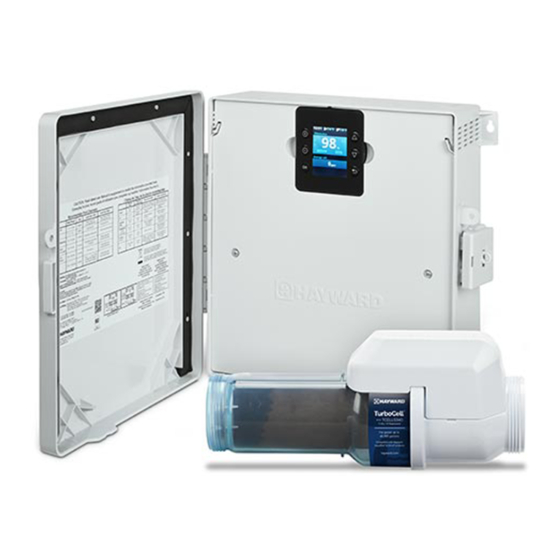
• Can generate chlorine using a broad range of salt concentrations from 1200 PPM to 8000 PPM • Can control and schedule a Hayward Variable Speed (VSP) pump using the internal RS-485 connection, a Pentair VSP using a Hayward HLPMPCONV converter (sold separately) or a single speed pump using a Hayward Smart Relay (sold separately) •... - Page 5 AquaRite S3 Overview...
- Page 6 • The conversion occurs in the electrolytic cell, also known as the cell (used throughout this guide). • Power is sent from the AquaRite S3 control center to the cell when chlorine production is scheduled (based on time percentage). •...
-
Page 7: Aquarite S3: Main Pcb Layout
AquaRite S3 Main PCB Layout AC Power for expansion board. If fuse is good AC mains voltage is present across contacts. Low voltage and signals for expansion board. Inadvertent shorts can cause damage. Standard Hayward RS-485 (HPN) connector. 12mm coin cell battery holder for real time clock. -
Page 8: Aquarite S3: Main Menu Layout
AquaRite S3 Main Menu Air Temperature - Current air temperature reading at the AquaRite S3. Current Time - If the AquaRite S3 controls the filter pump, Water Temperature - Current the pump’s schedule will water temperature reading with reference this time. - Page 9 AquaRite S3® How To Guide:...
-
Page 10: Remove Font Panel
How To: Remove Front Panel Front Panel Removal Instructions: Pull the display away from the panel and place on top of the enclosure. Remove the 3 screws then pull the front panel from the enclosure. It is not necessary to disconnect the display wiring. Lay the display on top of the unit Remove 3 Screws... -
Page 11: Navigate The Menu
How To: Navigate the Menu Navigation and Configuration Wizard: Note that the AquaRite S3 uses 6 push buttons to navigate the menu and set values. The functions of these buttons are shown below. -
Page 12: How To
How To: Upgrade Firmware (Main Board) Remove the front panel (page 10) and Insert the USB drive into the USB Slot on the Main PCB (diagram on page 7) and follow the steps provided below: Step 2 Step 1 Press OK to enter the Main Menu, then scroll Scroll down to the bottom of the Main Menu Screen and select “Service Mode”... - Page 13 How To: Upgrade Firmware (Main Board) e firmware and press OK, if not press cancel to return to file selection menu. Step 5 Step 6 Select Main Board and press OK. Select the firmware named MAIN for Main Board upgrade and press OK. Step 7 Step 8 Confirm the firmware and press OK, the system...
- Page 14 How To: Upgrade Firmware (Display) Step 9 Step 10 Complete Steps 1-4 of Main Board Update then Select the firmware labeled DISPLAY select the Display and press OK. and press OK. Step 11 Step 12 Confirm the firmware and press OK, if not press The system will now perform the update.
- Page 15 How To: Upgrade Firmware (Display) Step 13 Step 14 The system will delete the old Display firmware Now the system will install the updated Firmware. and continue with the upgrade. Step 15 Step 16 Once the update is complete you will hear 3 The system is now updated and ready to use.
-
Page 16: Set Schedules
How To: Set Schedule You can only set a schedule if you have a VS Pump or Smart Relay connected to the system. Step 1 Step 2 Press OK to enter the Main Menu. Scroll down to Press the + or - button to enable the schedule Schedule and press OK. - Page 17 How To: Set Schedule Step 5 Step 6 Once all 3 speeds have been adjusted press OK Press down arrow to desired schedule. Once to continue programming schedules. highlighted use + or - to edit the start time. To disable schedule set 12:00 to 12:00 Step 7 Step 8 Once the start time is set, use the up arrow to move...
-
Page 18: Set Pump Speeds
How To: Set Pump Speeds Step 1 Step 2 Press Ok to enter the Main Menu then scroll Once in System settings, scroll down to Service down to System settings and press OK. settings and press OK. Step 3 Step 4 Once in Service Settings, select Edit config. - Page 19 How To: Set Pump Speeds Step 5 Step 6 Use up or down arrow to navigate to the preset Use the up or down arrows to navigate between speed and press + or - to enter the adjustment the columns. Use the + or - menu to adjust the menu.
-
Page 20: Adjust Chlorine Settings
How To: Adjust Chlorinator Settings Step 1 Step 2 Press OK to enter the Main Menu, then press OK Once in the Chlorination Menu, you will need to again to enter the Chlorination Menu. enable the Chlorinator by pressing + or - button. Step 3 Step 4 Press the down arrow to Chlorine output level and... - Page 21 How To: Adjust Chlorinator Settings Step 5 Step 6 Select the time by pressing Up or Down arrows. Press down button to go to Chlorination Press OK when desired time is highlighted. Diagnostics and press OK. Step 7 Step 8 In the diagnostics screen you can view everything Once Chlorine output is changed, you can see the with the S3 Cell.
- Page 22 Chlorinator Diagnostics Heading Description Internal temperature of the T Cell. Used to scale back CELL TEMP output for high and low water temperatures Instant Salt displayed and measured only while INSTANT SALT chlorinating. Running average of instant salt readings. At initial AVERAGE SALT startup will show a seed value of 2800 ppm.
-
Page 23: Adjust Heating Settings
How To: Adjust Heating Settings Step 1 Step 2 Use + or - to Enable or Disable the Heater then Press OK to enter Main Menu, then scroll down to Heating Menu and Press OK. press down arrow to the temperature setting. Step 3 Step 4 To adjust the set temperature use + or - then... - Page 24 How To: Adjust Heating Setting Step 5 Step 6 Heater Extend will Cool Down will not temporarily suspend allow the pump to the filter pump timer be shut off for 5 and allow the pump to minutes while the run continually until heater is cooling the set temperature down.
- Page 25 AquaRite S3® Troubleshooting Guide...
-
Page 26: Troubleshooting
AQR S3 Troubleshooting LED Not 120/240 VAC 4AT Fuse FUS1 Fuse Replace Board Blinking present? Blown? Blown? Resolve Hardware Issue Replace Fuse source power Replace Board issue Display not Cable connected 5VDC between Replace On: Check all to back of the red and black Display display? - Page 27 Troubleshooting: LED Not Blinking Step 1 Step 2 Verify the LED on the Main Board is blinking for a Check that proper power is supplied to board duration of 3 seconds on and 3 seconds off. through the pigtail connector, correct if necessary. If not, go to Step 2.
- Page 28 Troubleshooting: LED Not Blinking Step 5 Step 6 If power is present and fuses have continuity, Verify that surface mount FUS1 isn’t open. If open then this is a hardware failure. Replace main PCB then replace the board, otherwise go to Step 6.
-
Page 29: Display Not Turning On
Troubleshooting: Blank Display Step 7 Step 8 Check everything from section “LED Not Blinking” Cable connected at back of display and in good condition, if not replace the harness. Go to Step 9. pages 27-28 then proceed to Step 8. Step 9 Step 10 Unplug cable from display and check for 5 VDC... -
Page 30: Water Temperature Sensor
Troubleshooting: Water Temperature Sensor Water temperature sensor is missing or damaged. Water temperature sensor will be grayed out Ensure sensor is properly wired to the correct when there is no flow detected in the system. terminal labeled SENS1 POOL. If wiring is correct and wire isn’t damaged, replace the sensor. -
Page 31: Air Temperature Sensor
Troubleshooting: Air Temperature Sensor Air temperature sensor is missing or damaged. Air temperature sensor is disabled in the System Ensure sensor is properly wired to the correct config menu. Everything in the system will still be terminal labeled SENS2 AIR. If wiring is correct and fully functional without the sensor except for wire isn’t damaged, replace the sensor. -
Page 32: Cover Sensor
Troubleshooting: Cover Sensor External Pool Cover sensor is active. The You can disable or enable the sensor through the External Pool Cover sensor is closed. This Main menu. You can also make changes to sensor is wired to SENS3 COVER terminal. chlorination, pump, and pump speed. -
Page 33: No Flow
Troubleshooting: No Flow No Flow is indicating that the Flow switch is not Verify if the sensors are working through Service receiving enough flow to close. Ensure that the mode – Sensors. From this menu you can verify the system has enough flow and that the flow switch is current status of the Air and Water Temperature properly plugged in, and the wire isn’t damaged. - Page 34 Troubleshooting: No Flow Pump Running & Valves are Set? Verify 12” of Straight Pipe Step 1 Step 2 Verify the pump is running & valves are positioned so It is recommended for the flow switch to have 12” of the flow switch is receiving water. IF the pump is not straight pipe preceding it (the S3 Cell counts as straight ON or the valve are not correctly set, resolve that first, pipe).
- Page 35 Troubleshooting: No Flow The flow switch only works in one orientation. An arrow (molded into the top of the flow switch) indicates the direction water should be flowing through the switch. Verify Flow Switch Orientation Unplug Connector & Inspect Step 3 Step 4 Verify the arrows (located on switch top) are pointing Unplug the flow switch connector &...
- Page 36 Troubleshooting: No Flow TIP: Carry a working flow switch, because it is a great tool to have available. It will help when trying to determine whether an existing switch is failing, or the main board is not sending or receiving the signal. Test with New Switch Replace Main PCB Step 5...
- Page 37 Troubleshooting: No Flow Switch is Pump ON & Flow switch preceded by No Flow valves are orientation is 12” straight correct? correct? pipe? Turn pump ON Turn pump Consider Problem & correct OFF & rotate moving switch solved valves. switch Install new Pump &...
-
Page 38: Low Cell Temperature
Troubleshooting: Low Cell Temperature The LCD display will read “---” when the cell is reading water temps below 50° F. When the Cell temperature sensor reads below 50 The cell temperature can be verified through the degrees the cell will shut off and not generate. diagnostics menu. -
Page 39: Cell Messages: 3.1
AQR S3 Troubleshooting Cell Messages: 3.1 Reason Possible Action Inspect Cell Message occurs every 500 hours. Press OK to dismiss the message and resets the cell. Cell Exhausted Cell has operated beyond its service life and requires replacement. Cell Missing Cell cable is unplugged or damaged or the connector is damaged. -
Page 40: Chlorination
AQR S3 Troubleshooting Chlorination Output: 4.1 Reason Possible Action Output won’t go above 20% Cell temperature is 60F or below Output won’t turn on • Cell temperature is below 50F or above 120F • Chlorinator is disabled • Insufficient water flow •... -
Page 41: Freeze Protect
AQR S3 Troubleshooting Freeze Protect: 5.1 Reason Possible Action Freeze Protect • Allows equipment to continue running when entering freeze protect. • Super chlorinate will pause during freeze protect • If the system is in freeze protect manual setting changes will require disabling freeze protect. -
Page 42: Not Able To Upgrade Firmware
AQR S3 Troubleshooting Firmware Update: 6.1 Reason Possible Action Firmware Won't Appear • USB drive must be FAT32 format • Firmware files must be in root directory • Must be less that 32 files on USB drive • Some USB drives may not be compatible. -
Page 43: Additional Information
Even if a S3 Cell appears clean, equipment. It is highly recommended to use a it may still require cleaning if salt accuracy is off AND/OR Hayward Cell Cleaning Stand as shown chlorine production has diminished. (GLX-CELLSTAND) NOTE: ALWAYS WEAR PROPER EYE PROTECTION AND PROTECTIVE GLOVES. - Page 44 Cleaning the S3 Cell (Cont.) The S3 draws amperage when power is applied, during chlorination. The amperage draw will be impaired when calcium and other debris exist within the cell’s electrolytic grid; this in turn effects the salt reading and chlorination efficiency. NOTE: ALWAYS ADD ACID TO WATER! NEVER ADD WATER TO ACID.
-
Page 45: Salt Addition Chart
Salt Addition Chart: lbs. required for 3200ppm Pool Size - Gallons Current Salt Level 8,000 10,000 12,000 14,000 16,000 18,000 20,000 22,000 24,000 26,000 28,000 30,000 32,000 34,000 36,000 38,000 40,000 1013 1067 1000 1000 1200 1400 1600 1800 2000 2200 2400 2600...