Table of Contents
Advertisement
Quick Links
Advertisement
Table of Contents

Related Manuals for TRENDnet TE100-S24WS

Summary of Contents for TRENDnet TE100-S24WS
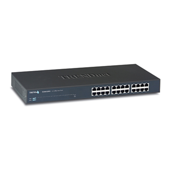
- Page 1 24-Port 10/100Mbps Fast Ethernet Web Smart Switch User’s Guide...
-
Page 3: Fcc Warning
FCC Warning This equipment has been tested and found to comply with the regulations for a Class A digital device, pursuant to Part 15 of the FCC Rules. These limits are designed to provide reasonable protection against harmful interference when the equipment is operated in a commercial environment. - Page 4 UL Warning a) Elevated Operating Ambient Temperature- If installed in a closed or multi-unit rack assembly, the operating ambient temperature of the rack environment may be greater than room ambient. Therefore, consideration should be given to installing the equipment in an environment compatible with the manufacturer's maximum rated ambient temperature (Tmra).
-
Page 5: Table Of Contents
TABLE OF CONTENT About This Guide... 1 Purpose... 1 Terms/Usage ... 1 Introduction... 3 Fast Ethernet Technology ... 3 Switching Technology ... 4 VLAN (Virtual Local Area Network) ... 5 Features ... 5 Unpacking and Installation ... 7 Unpacking ... 7 Installation... - Page 6 Monitor List ... 17 Device Setting ... 19 Toolbar... 20 Configuring the Switch ... 21 Login ... 22 Main Menu... 24 Configuring Setup Setting... 24 Port Settings ... 24 VLAN Settings (Virtual Local Area Network) ... 26 Device Status ... 27 Statistic...
-
Page 7: About This Guide
This guide discusses how to install your 24-Port 10/100Mbps Fast Ethernet Web Smart Switch. Terms/Usage In this guide, the term “Switch” (first letter upper case) refers to your 24-Port 10/100Mbps Fast Ethernet Web Smart Switch, and “switch” (first letter lower case) refers to other Ethernet switches. -
Page 9: Introduction
INTRODUCTION This chapter describes the features of the 24-Port 10/100Mbps Fast Ethernet Web Smart Switch and some background information about Ethernet/Fast Ethernet switching technology. Fast Ethernet Technology The growing importance of LANs and the increasing complexity of desktop computing applications are fueling the need for high performance networks. -
Page 10: Switching Technology
Switching is a cost-effective way of increasing the total network capacity available to users on a local area network. A switch increases capacity and decreases network loading by dividing a local area network into different segments, which don’t compete with each other for network transmission capacity. -
Page 11: Vlan (Virtual Local Area Network)
Cost Reduction, VLANs can be used to create multiple broadcast domains, thus eliminating the need of expensive routers. Port-based (or port-group) VLAN is the common method of implementing a VLAN, and is the one supplied in the Switch. Features 24×10/100Mbps Auto-negotiation Ethernet ports... - Page 12 Supports Back-pressure flow control for half-duplex mode ports Supports Port-setting for Speed/Disable, Flow control Supports port-base VLAN Supports port-base QoS Optional one port 100BASE-FX Fiber module in the rear panel for length extension Easy configuration via WEB Browser Easy setting via Web Management Utility Standard 19”...
-
Page 13: Unpacking And Installation
The site where you install the hub stack may greatly affect its performance. When installing, consider the following pointers: Install the Switch in a fairly cool and dry place. See Technical Specifications for the acceptable temperature and humidity operating ranges. -
Page 14: Rack Mounting
Install the Switch on a sturdy, level surface that can support its weight, or in an EIA standard-size equipment rack. For information on rack installation, see the next section, Rack Mounting. When installing the Switch on a level surface, attach the rubber feet to the bottom of each device. -
Page 15: Connecting Network Cable
AC Power The Switch used the AC power supply 100-240V AC, 50-60 Hz. The power switch is located at the rear of the unit adjacent to the AC power connector and the system fan. The switch’s power supply will adjust to the local power source automatically and may be turned on... -
Page 17: Identifying External Components
This chapter describes the front panel, rear panel, and LED indicators of the Switch. Front Panel The figure below shows the front panels of the Switch. Figure 3. Front panel of 24-port 10/100Mbps Fast Ethernet Switch LED Indicator: Comprehensive LED indicators display the status of the switch and the network (see the LED Indicators chapter below). -
Page 18: Rear Panel
AC Power Connector Fiber Module Slot Reset Button Figure 4. Rear panel of the Switch 100Base-FX Fiber Module Slot This is the slot when the users need to connect to 100Base-FX Fiber Optical device, you can use the optional 100Base-FX Fiber Module to plug into the slot. -
Page 19: Understanding Led Indicators
Figure 5. LED indicators of the Switch Power and System LEDs POWER: Power Indicator : When the Power LED lights on, the Switch is receiving power. : When the Power turns off or the power cord has improper connection. SYSTEM: Management Indicator Blinking : When the CPU is working, the System LED is blinking. -
Page 20: Fiber Module Leds
100Mbps : When the 100Mbps LED lights on, the respective port is connected to a 100Mbps Fast Ethernet network. : When the respective port is connected to a 10Mbps Ethernet network, or no link. Fiber Module LEDs FX Link/ACT: Link/Activity : When the fiber module is installed and connected to an Ethernet network, the FX Link/ACT LED lights on. -
Page 21: Configuration
CONFIGURATION Through the Web Browser you can configure the Switch such as VLAN, Port Setting, and System Setting …etc. With the attached Web Management Utility, you can easily discover all the Web Management Switch, assign the IP Address, changing the password and upgrading the new firmware. -
Page 22: Discovery List
Figure 6. Web Management Utility The Web Management Utility was divided into four parts, Discovery List, Monitor List, Device Setting and Toolbar function, for details instruction, follow the below section. Discovery List This is the list where you can discover all the Web management devices in the entire network. -
Page 23: Monitor List
System word definitions in the Discovery List: MAC Address: Shows the device MAC Address. IP Address: Shows the current IP address of the device. Protocol version: Shows the version of the Utility protocol. Product Name: Shows the device product name. System Name: Shows the appointed device system name. - Page 24 The symbol “ ” represents the trap signal arise, this symbol will disappear after you review and click on the event record. Note: In order to receive Trap information, switch has to be configured with Trap IP and Trap Events in Web browser, which are available in the Trap Setting Menu (see Page 33 for detail).
-
Page 25: Device Setting
Device Setting You can set the device by using the function key in the Device Setting Dialog box. Configuration Setting: In this Configuration Setting, you can set the IP Address, Subnet Mask, Gateway, Set Trap to (Trap IP Address), System name and Location. Select the device in the Discovery list or Monitor List and press this button, then the Configuration Setting window will pop out as Figure 9, after filling in the data that you want to change;... -
Page 26: Toolbar
Firmware Upgrade: When the device has a new function, there will be a new firmware to update the device, use this function to update. Web Access: Double click the device in the Monitor List or select a device in the Monitor List and press this “Web Access” button to access the device in Web browser. -
Page 27: Configuring The Switch
In the “Help TAB”, there is About function, it will show out the version of the Web Management Utility. Configuring the Switch The 24-Port 10/100Mbps Fast Ethernet Web Smart Switch has a Web GUI interface for smart switch configuration. The Switch can be configured through the Web Browser. A network administrator can manage, control and monitor the switch from the local LAN. -
Page 28: Login
PC must be set on the same IP network. For example, when the default network address of the default IP address of the Web Smart Switch is 192.168.0.1, then the manager PC should be set at 192.168.0.x (where x is a number between 2 and 254), and the default subnet mask is 255.255.255.0. - Page 29 After entering the password, the main page comes up; the screen will display the device status. Figure 14. Device Status...
-
Page 30: Main Menu
Main Menu When the main page appears, find the Setup menu in the left side of the screen (Figure 15). Click on the setup item that you want to configure. There are nine options: Port Settings, VLAN Settings, Device Status, Statistic, System Settings, Trap Setting, Password Setting, Backup Setting and Reset Setting as shown in the Main Menu screen. - Page 31 The Link Status in the screen will show the connection speed and duplex mode; else this dialog box will show down when the port is disconnected. Figure 16. Port Configuration To change the port setting, click on the ID parameter to enter to the selected port to configure its Speed/Disable, Flow control and QoS setting.
-
Page 32: Vlan Settings (Virtual Local Area Network)
Flow Control: This setting determines whether or not the Switch will be handling flow control. Set FlowCtrl to Enable for avoiding data transfer overflow. Or it sets to Disable; there is either no flow control or other hardware/software management. When the port is set to forced mode, then the flow control will automatically set to Disable. -
Page 33: Device Status
Figure 19. VLAN Settings Device Status Click on the “Status” to present the device status on this screen, it will show the System Status, Port Status and VLAN Status. Press “Refresh” when you need to renew the posted information. Statistic The Statistic Menu screen will show the status of each port packet count. -
Page 34: System Setting
For Detail packet information, click on the ID parameter as Figure 21. Figure 21. Port Statistic System Setting The System Setting includes the System name, Location name, Login Timeout, IP Address, Subnet Mask and Gateway. Through the Web Management Utility, you can easily recognize the device by using the System Name and the Location Name. -
Page 35: Trap Setting
Trap Setting The Trap Setting enables the device to monitor the Trap through the Web Management Utility, set the Trap IP Address of the manager where the trap to be sent. System Events: Monitoring the system’s trap. Device Bootup: a trap when booting up the system. Illegal Login: a trap when there is a wrong password login, and it will record from where the IP was been login. -
Page 36: Set Password
Switch will restore to the default setting. Backup Setting The backup tools help you to backup the current setting of the Switch. Once you need to backup the setting, press the “Backup” button to save the setting. -
Page 37: Reset Setting
Figure 25. Backup Setting Note: when restoring a recorded file, the current password will not be erased. Reset Setting The Factory Reset button helps you to reset the device back to the default setting from the factory. Be aware that the entire configuration will be reset, the IP address of the device will be set to default setting 192.168.0.1. -
Page 39: Technical Specifications
TECHNICAL SPECIFICATIONS Standards Protocol Data Transfer Rate Topology Network Cables Number of Ports AC inputs Power Consumption Temperature Humidity Dimensions EMI: Safety: General IEEE 802.3 10BASE-T Ethernet IEEE 802.3u 100BASE-TX Fast Ethernet IEEE 802.3u 100BASE-FX Fast Ethernet CSMA/CD Ethernet: 10Mbps (half duplex), 20Mbps (full-duplex) Fast Ethernet: 100Mbps (half duplex), 200Mbps (full- duplex) Star 10BASET: 2-pair UTP Cat. - Page 40 Transmits Method: RAM Buffer: Filtering Address Table: Packet Filtering/Forwarding Rate: MAC Address Learning: Performance Store-and-forward 768K bytes per device 4K entries per device 10Mbps Ethernet: 14,880/pps 100Mbps Fast Ethernet: 148,800/pps Automatic update...