Advertisement
Quick Links
2
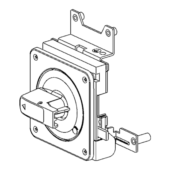
TemBreak
Breaker-Mounted External Operating Handle
Instruction Manual
(Type): T2HB80
This device allows the breaker installed in a motor
control center or switchboard to be operated manually
without the need for opening the panel of the motor
control center or switchboard.
Please retain this manual for future reference. The Manufacturer assumes no responsibility for
damages resulting from non-application or incorrect application of the instructions provided herein.
Contact Us:
7-2-10 Kamihigashi, Hiranoku, Osaka
547-0002, Japan
TEL:81-6-6791-9323/ FAX:81-6-6791-9274
http://www.terasaki.co.jp
Web Site: http://www.terasaki.co.jp
kiki-info@terasaki.co.jp
Email: int-sales@terasaki.co.jp
2G0829SAA
The Mounting Direction Changing Procedure
No.2
Handle catch
Screw head
Rotate the handle until the screw head is
visible at the handle catch.
Lock adjustment plate a (Metal)
Lock adjustment plate b (Plastic)
For overseas specifications
Packaged Items
Panel plate
Hook holder
M4 14- 4pcs.
M5 95- 2pcs. , M5 105- 2pcs.
Flat head screws black
Pan head screws
Gasket for dust protection optional
Orient the lock adjustment plate depending on the changes in breaker mounting direction. When
changing the handle to the left power supply type, for example, select orientation "B" from the table
shown below.
Lock adjustment plate orientations
for Upper power
for Left power
supply type
supply type
Mounting direction
Specifications
Japanese
Specifications
Standard
Lock adjustment plate
orientations
Overseas
Specifications
Standard
Applicable Breaker Types
Handle type
S630-CF, S630-NF, S630-NE, S800-CF, S800-NF, S800-NE
S1000-CE
T2HB80
S630-GN, S800-NN, S1000-NN
ZAS630-CF, ZAS630-NF, ZAS800-CF, ZAS800-NF
ZS630-CF, ZS630-NF, ZS800-CF, ZS800-NF
Assembly Tools
Handle
4.5 50
Safety Notices
Be sure to read these Instructions and other associated documents accompanying the product
thoroughly to be familiarize yourself with the product handling, safety information, and all other
precautions before mounting, using, servicing, or inspecting the product. In these Instructions,
safety notices are divided into " Warning" and " Caution" according to the hazard level:
Warning : A warning notice with this symbol indicates that neglecting the suggested procedure
or practice could be fatal or result in serious personal injury.
Caution : A caution notice with this symbol indicates that neglecting the suggested procedure or
Key optional
practice could result in moderate or slight personal injury and/or property damage.
"B"
for Right power
supply type
Handle installation positions
for Upper power
supply type
Mounting direction
Handle installation
positions
Standard
Note that failing to observe caution notices could result in serious injury/damage in some situations.
Because safety notices contain important information, be sure to read and observe them.
Applicable breaker types
Never touch live terminals. Doing so may result in electric shock.
Electrical work should only be undertaken by suitably qualified persons.
Prior to commencing any work on the product, open an upstream circuit breaker or isolator
No.2
to ensure that no voltage is applied to the product. Otherwise, electrical shock may result.
To remain the switchboard panel closed securely, use appropriate hardware in addition to
the panel lock of the handle. Using the panel lock only may result in damage to the
switchboard panel.
When the breaker trips open automatically, remove the cause, then return the handle to
the |(ON) position. Should a fault be interrupted, the breaker must be inspected.
Otherwise, a fire may result.
Do not apply excessive force to the operating knob. Otherwise, damage may occur.
Visually check the inside from the handle catch to see if the handle is engaged with the
gear properly. See the table below.
Referring to the table below, install the handle in the
position matched to the change in breaker mounting
Mounting direction
direction.
Handle and gear
engagement
for Left power
for Right power
supply type
supply type
Warning
Operation Precautions
Caution
Installation Precautions
OFF
Operation Precautions
ON
Handle and gear engagement
for Upper power
for Left power
for Right power
supply type
supply type
supply type
Standard
1.5 - 2.0N m
No.2
Advertisement

Related Manuals for TERASAKI TemBreak T2HB80


Summary of Contents for TERASAKI TemBreak T2HB80
- Page 1 547-0002, Japan Warning : A warning notice with this symbol indicates that neglecting the suggested procedure TEL:81-6-6791-9323/ FAX:81-6-6791-9274 http://www.terasaki.co.jp Web Site: http://www.terasaki.co.jp or practice could be fatal or result in serious personal injury. kiki-info@terasaki.co.jp Email: int-sales@terasaki.co.jp Caution : A caution notice with this symbol indicates that neglecting the suggested procedure or...
- Page 2 Mounting Panel Opening Procedure Reset Open Type For detailed mounting dimensions, refer to the catalogue. Panel knob M8 25 mm 14.8-18.6N m M5 95 mm 3.6-4.4N m M5 105 mm 3.6-4.4N m M4 14 mm OFF Open Type 1.0-1.7N m The figure shows the upper power supply type.