Table of Contents
Advertisement
Quick Links
Advertisement
Table of Contents

Related Manuals for Supermicro X6DHT-G

Summary of Contents for Supermicro X6DHT-G
- Page 1 ® UPER X6DHT-G USER’S MANUAL Revision 1.1a...
- Page 2 Santa Clara County in the State of California, USA. The State of California, County of Santa Clara shall be the exclusive venue for the resolution of any such disputes. Supermicro's total liability for all claims will not exceed the price paid for the hardware product.
-
Page 3: Manual Organization
This manual is written for system integrators, PC technicians and knowledgeable PC users. It provides information for the installation and use of the X6DHT-G motherboard. The X6DHT-G supports single or dual Intel EM64T (Nocona ) processors at a 800 MHz front side bus. Based upon... -
Page 4: Table Of Contents
Checklist ... 1-1 Contacting Supermicro ... 1-2 X6DHT-G Image ... 1-3 X6DHT-G Layout ... 1-4 X6DHT-G Quick Reference ... 1-5 Motherboard Features ... 1-6 Intel E7520 (Lindenhurst) Chipset: System Block Diagram ... 1-8 Chipset Overview ... 1-9 Special Features ... 1-10 PC Health Monitoring ... - Page 5 Chassis Intrusion ... 2-14 Serial Ports ... 2-14 Universal Serial Bus (USB0/1) ... 2-15 Extra Universal Serial Bus Headers (USB2/3) ... 2-15 GLAN (Ethernet Ports) ... 2-16 ATX PS/2 Keyboard and Mouse Ports ... 2-16 Fan Headers ... 2-17 Power LED/Speaker Header ... 2-17 Wake-On-Ring ...
- Page 6 X6DHT-G User's Manual No Video ... 3-1 Memory Errors ... 3-2 Losing the System’s Setup Configuration ... 3-2 Technical Support Procedures ... 3-2 Frequently Asked Questions ... 3-3 Returning Merchandise for Service ... 3-4 Chapter 4: BIOS Introduction ... 4-1 Running Setup ...
-
Page 7: Chapter 1: Introduction
Checklist Congratulations on purchasing your computer motherboard from an ac- knowledged leader in the industry. Supermicro boards are designed with the utmost attention to detail to provide you with the highest standards in quality and performance. Check that the following items have all been in- cluded with your motherboard. -
Page 8: Contacting Supermicro
X6DHT-G User's Manual Contacting Supermicro Headquarters Address: Super Micro Computer, Inc. 980 Rock Ave. San Jose, CA 95131 U.S.A. Tel: +1 (408) 503-8000 Fax: +1 (408) 503-8008 Email: marketing@supermicro.com (General Information) support@supermicro.com (Technical Support) Web Site: www.supermicro.com Europe Address: Super Micro Computer B.V. -
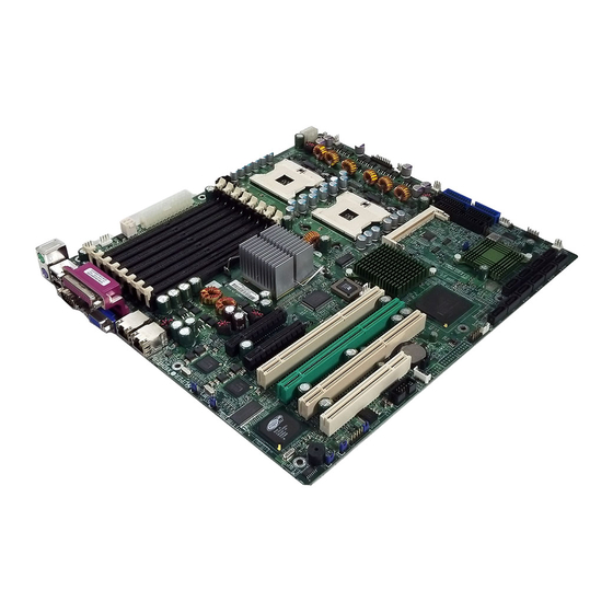
Page 9: X6Dht-G Image
Chapter 1: Introduction Figure 1-1. X6DHT-G Image... -
Page 10: X6Dht-G Layout
X6DHT-G User's Manual Figure 1-2. JPW1 LAN1 LAN2 Notes: 1. Jumpers not indicated are for testing only. 2. See Chapter 2 for detailed information on jumpers, I/O ports and JF1 front panel connections. 3. " " indicates the location of Pin 1. - Page 11 Quick Reference (X6DHT-G) (*Please refer to Chapter 2 for pin definitions and detailed information.) Jumper Description 3rd PW Supply Detect Alarm Reset Enable JBT1 CMOS Clear JPL1/JPL2 GLAN1/GLAN2 Enable JPG1 VGA Enable JPS1 Marvell SATA Controller Enable Watch Dog Enable...
-
Page 12: Motherboard Features
X6DHT-G User's Manual Motherboard Features ® • Single or dual Intel (system) bus speed. M e m o r y • Eight 184-pin DIMM sockets supporting up to 16 GB (DDR 333) or 32 GB (DDR 266) Registered ECC DDR 333/266 (PC2700/PC2100) SDRAM Chipset •... - Page 13 Chapter 1: Introduction ACPI Features • Microsoft OnNow • Slow blinking LED for suspend state indicator • Main switch override mechanism Onboard I/O • One IPMI 2.0 socket • Two Intel 82541G1 Gigabit Ethernet controllers • 2 EIDE Ultra DMA/100 bus master interfaces •...
- Page 14 X6DHT-G User's Manual 1_PCIX-100 1_PCIX-100 Slot Slot SATA SATA HC2_8Ports HC2_8Ports PCIX BUS(100 MHZ) PCIX BUS(100 MHZ) 1_PCIX-100 1_PCIX-100 GRN_Slot GRN_Slot 1_PCIX-133 1_PCIX-133 Slot Slot PCIX BUS(133 MHZ) PCIX BUS(133 MHZ) 1_PCIX-E 1_PCIX-E (X8)Slot (X8)Slot 1_PCIX-E 1_PCIX-E (X8)Slot (X8)Slot Figure 1-9.
-
Page 15: Chipset Overview
Chipset Overview Built upon the functionality and the capability of the 7520 Lindenhurst chipset, The X6DHT-G motherboard provides the performance and feature set required for dual processor-based servers, with configuration options optimized for communications, presentation, storage, computation or data- base applications. The Intel E7520 (Lindenhurst) chipset... -
Page 16: Special Features
X6DHT-G User's Manual Special Features Recovery from AC Power Loss BIOS provides a setting for you to determine how the system will respond when AC power is lost and then restored to the system. You can choose for the system to remain powered off (in which case you must hit the power switch to turn it back on) or for it to automatically return to a power- on state. -
Page 17: Acpi Features
damage to the CPU. The onboard chassis thermal circuitry can monitor the overall system temperature and alert users when the chassis temperature is too high. CPU Fan Auto-Off in Sleep Mode The CPU fan activates when the power is turned on. It continues to operate when the system enters Standby mode. - Page 18 X6DHT-G User's Manual In addition to enabling operating system-directed power management, ACPI provides a generic system event mechanism for Plug and Play and an oper- ating system-independent interface for configuration control. ACPI lever- ages the Plug and Play BIOS data structures while providing a processor architecture-independent implementation that is compatible with the Win- dows 2000, Windows 2003 and Windows Vista Operating Systems.
-
Page 19: Power Supply
It is even more important for processors that have high CPU clock rates. The SUPER X6DHT-G accommodates ATX 24-pin power supplies. Although most power supplies generally meet the specifications required by the CPU, some are inadequate. You should use one that will supply at least 400W of power. - Page 20 X6DHT-G User's Manual cessor interrupt system. Both UARTs provide legacy speed with baud rate of up to 115.2 Kbps as well as an advanced speed with baud rates of 250 K, 500 K, or 1 Mb/s, which support higher speed modems.
-
Page 21: Chapter 2: Installation
Static-Sensitive Devices Electrostatic Discharge (ESD) can damage electronic components. To pre- vent damage to your system board, it is important to handle it very carefully. The following measures are generally sufficient to protect your equipment from ESD. Precautions • Use a grounded wrist strap designed to prevent static discharge. •... -
Page 22: Xeon Em64T Processor And Heatsink Installation
X6DHT-G User's Manual Xeon EM64T Processor and Heatsink Installation When handling the processor package, avoid placing direct pressure on the label area of the fan. motherboard on a conductive surface, which can damage the BIOS battery and prevent the system from booting up. - Page 23 CEK Heatsink Installation 1. Do not apply any thermal grease to the heatsink or the CPU die-the required amount has already been applied. 2. Place the heatsink on top of the CPU so that the four mounting holes are aligned with those on the retention mechanism.
- Page 24 X6DHT-G User's Manual To Un-install the Heatsink Caution! We do not recommend that the CPU or the heatsink be removed. How- ever, if you do need to un-install the heatsink, please follow the instructions below to uninstall the heatsink to prevent damage done to the CPU or the CPU socket.
- Page 25 Triangle Mounting the Motherboard in the Chassis All motherboards have standard mounting holes to fit different types of chassis. Make sure that the locations of all the mounting holes for both the motherboard and the chassis match. Although a chassis may have both plastic and metal mounting fasteners, metal ones are highly recommended because they ground the motherboard to the chassis.
-
Page 26: Installing Dimms
Repeat for all modules (see step 1 above). Memory Support The X6DHT-G supports up to 16/32 GB Registered ECC DDR 333/266 (PC2700/PC2100) memory. All motherboards were designed to support 2GB (DDR333)/4GB (DDR 266) modules in each slot, but has only been verified... -
Page 27: I/Oports/Control Panel Connectors
Figure 2-2. To Install: In- s e r t m o d u l e vertically and p r e s s d o w n until it snaps i n t o p l a c e . Pay attention t o t h e a l i g n - ment notch at the bottom. - Page 28 JF1 contains header pins for various buttons and indicators that are nor- mally located on a control panel at the front of the chassis. These connec- tors are designed specifically for use with Supermicro server chassis. See Figure 2-4 for the descriptions of the various control panel buttons and LED indicators.
-
Page 29: Connecting Cables
Connecting Cables ATX Power Connector The main power supply connector (JPW1) on the X6DHT-G meets the SSI (Superset ATX) specification. You can only use a 24-pin power supply cable on the motherboard. Make sure that the orientation of the connector is correct. You... -
Page 30: Nmi Button
X6DHT-G User's Manual NMI Button The non-maskable interrupt button header is located on pins 19 and 20 of JF1. Refer to the table on the right for pin definitions. Power LED The Power LED connection is lo- cated on pins 15 and 16 of JF1. -
Page 31: Hdd Led
HDD LED The HDD LED connection is located on pins 13 and 14 of JF1. Attach the hard drive LED cable here to display disk activity (for any hard drives on the system, including SCSI, Serial ATA and IDE). See the table on the right for pin definitions. -
Page 32: Overheat/Fanfail Led
X6DHT-G User's Manual Overheat/FanFail LED Connect an LED to the OH/Fan Fail connection on pins 7 and 8 of JF1 to provide advanced warning of chassis overheating or system fan failure. Refer to the table on the right for pin definitions. -
Page 33: Reset Button
Reset Button The Reset Button connection is lo- cated on pins 3 and 4 of JF1. At- tach it to the hardware reset switch on the computer case. Refer to the table on the right for pin definitions. Power Button The Power Button connection is located on pins 1 and 2 of JF1. -
Page 34: Chassis Intrusion
X6DHT-G User's Manual Chassis Intrusion A Chassis Intrusion header is lo- cated at JL1. Attach the appropri- ate cable to inform you of a chas- sis intrusion. Serial Ports The COM1 serial port is located under the parallel port and COM2... -
Page 35: Universal Serial Bus
Universal Serial Bus Two USB 2.0 ports are located be- side the PS/2 keyboard/mouse ports. USB0 is the bottom connector and USB1 is the top connector. See the table on the right for pin definitions. Front Panel Universal Serial Bus Headers Extra USB headers (FPUSB2/FPUSB3) can be used for front side USB access. -
Page 36: Glan (Ethernet Ports)
X6DHT-G User's Manual GLAN (Giga-bit Ethernet Ports) A G-bit Ethernet port (designated JLAN1/JLAN2) is located beside the VGA port on the IO backplane. This port accepts RJ45 type cables. ATX PS/2 Keyboard and PS/2 Mouse Ports The ATX PS/2 keyboard and PS/2... -
Page 37: Fan Headers
Fan Headers The X6DHT-G has eight fan headers (Fan1 to Fan8). Note: Fans 5-8 are 4- pin fans. However, Pins 1-3 of the fan headers are backward compatible with the traditional 3-pin fans. See the table on the right for pin definitions. *The on-... -
Page 38: Wake-On-Ring
X6DHT-G User's Manual Wake-On-Ring The Wake-On-Ring header is des- ignated JWOR. This function al- lows your system "awakended" by an incoming call to the modem when in suspend state. See the table on the right for pin definitions. You must have a Wake-On-Ring card and cable to use this feature. -
Page 39: Smb
System Management header is located at J11. Connect the appropriate cable here to uti- lize SMB on your system. See the table on the right for pin defini- tions. SMB Power (I Connector C Connector (J32), located be- tween the 8-pin PWR Connector and the 24-pin PWR Connector, monitors the status of PWR Sup- ply, Fan and system temperature. -
Page 40: Sata Activity Output Led
X6DHT-G User's Manual Marvell SATA SMB Power C) Connector The Marvell SATA I C Connector (JS10), located between IDE1 Slot and Chassis Intrusion Header, monitors the status of PWR Sup- ply, Fan and system temperature for Marvell Serial ATA ports. See the table on the right for pin defini- tions. -
Page 41: Overheat Led
LAN2 Pin Definitions (JOH) Number PWR Supply Fail LED Pin Definitions (PSF) Number This Note: This feature is only available when using redundant Supermicro power supplies. 12V 8-pin SMBus P W R P W R JPS1 JWOR 2-21 Chapter 2: Installation... -
Page 42: Jumper Settings
X6DHT-G User's Manual Jumper Settings Explanation of Jumpers To modify the operation of the motherboard, jumpers can be used choose between settings. umpers create shorts between two pins to change the function of the connector. Pin 1 is identified with a square solder pad on the printed circuit board. -
Page 43: Cmos Clear
CMOS Clear JBT1 is used to clear CMOS. Instead of pins, this "jumper" consists of contact pads to prevent the accidental clearing of CMOS. To clear CMOS, use a metal object such as a small screwdriver to touch both pads at the same time to short the connection. -
Page 44: Vga Enable/Disable
Alarm Reset The system will notify you in the event of a power supply failure. This feature as- sumes that Supermicro redundant power supply units are installed in the chassis. If you only have a single power supply installed, you should not connect anything to this jumper to prevent false alarms. -
Page 45: Rd Pwr Fault Detect
3rd PWR Supply PWR Fault Detect (J3P) The system can notify you in the event of a power supply failure. sumes that three power supply units are installed in the chassis, with one acting as a backup. If you only have one or two power supply units installed, you should disable this (the default setting) with J3P to prevent false alarms. -
Page 46: Onboard Indicators
X6DHT-G User's Manual Onboard Indicators GLAN LEDs The Gigabit Ethernet LAN ports (located beside the Video port) has two LEDs. The yellow LED indicates activity while the other LED may be green, orange or off to indicate the speed of the connec- tion. -
Page 47: Sata Presence Leds
Marvell SATA Presence LED Indicators Marvell Serial ATA Presence LED Indicators (DS1-DS8), located above Marvell SATA Ports 0-7, in- dicate the presence of Marvell SATA ports (0-7). See the table on the right for pin definitions. Marvell SATA Activity LED Indicators Marvell Serial ATA Activity LED In- dicators (DS9-DS16), located... -
Page 48: Parallel Port
X6DHT-G User's Manual Parallel Port, Floppy, IPMI and Hard Disk Drive Connections Note the following when connecting the floppy and hard disk drive cables: • The floppy disk drive cable has seven twisted wires. • A red mark on a wire typically designates the location of pin 1. -
Page 49: Floppy Connector
Floppy Connector The floppy connector is lo- cated between the IDE con- nectors and the IPMI socket. See the table below for pin definitions. IPMI 2.0 Socket The IPMI 2.0 Socket is located next to the Floppy Drive. See the table below for pin definitions. -
Page 50: Ide Connectors
X6DHT-G User's Manual IDE Connectors IDE Connectors are located on the edge of the mother- board. See the table on the right for pin definitions. JPW1 LAN1 LAN2 IDE Connector Pin Definitions Pin Number Function Reset IDE Host Data 7... -
Page 51: Chapter 3: Troubleshooting
Troubleshooting Procedures Use the following procedures to troubleshoot your system. followed all of the procedures below and still need assistance, refer to the ‘Technical Support Procedures’ and/or ‘Returning Merchandise for Service’ section(s) in this chapter. Note: Always disconnect the power cord before adding, changing or installing any hardware components. -
Page 52: Memory Errors
X6DHT-G User's Manual If you are a system integrator, VAR or OEM, a POST diagnos- tics card is recommended. For I/O port 80h codes, refer to Memory Errors 1. Make sure the DIMM modules are properly and fully installed. 2. Determine if different speeds of DIMMs have been installed and verify that the BIOS setup is configured for the fastest speed of RAM used. -
Page 53: Frequently Asked Questions
Question: What are the various types of memory that my mother- board can support? Answer: The X6DHT-G has eight 184-pin DIMM slots that support regis- tered ECC/Non ECC DDR 333/266 (PC2700/PC2100) SDRAM modules. It is strongly recommended that you do not mix memory modules of different speeds and sizes. -
Page 54: Returning Merchandise For Service
X6DHT-G User's Manual load the BIOS file to your computer. Unzip the BIOS update file and you will find the readme.txt (flash instructions), the phlash.exe (BIOS flash utility) files. Copy these files into a bootable floppy and reboot your system. Then, follow Readme.txt to continue flashing the BIOS. -
Page 55: Chapter 4: Bios
Introduction This chapter describes the Phoenix BIOS™ Setup utility for the X6DHT-G. The Phoenix ROM BIOS is stored in a flash chip and can be easily upgraded using a floppy disk-based program. Note: Due to periodic changes to the BIOS, some settings may have been added or deleted and might not yet be recorded in this manual. -
Page 56: Running Setup
X6DHT-G User's Manual Running Setup *Default settings are in bold text unless otherwise noted. The BIOS setup options described in this section are selected by choos- ing the appropriate text from the main BIOS Setup screen. All displayed text is described in this section, although the screen display is often all you need to understand how to set the options (See the next page). -
Page 57: Main Bios Setup Menu
Chapter 4: BIOS Main BIOS Setup Menu Main Setup Features System Time To set the system date and time, key in the correct information in the appropriate fields. Then press the <Enter> key to save the data. System Date Using the arrow keys, highlight the month, day and year fields, and enter the correct data. - Page 58 X6DHT-G User's Manual Serial ATA This setting allows the user to enable or disable the function of Serial ATA. The options are Disabled and Enabled. Serial ATA RAID Enable Select Enable to enable Serial ATA RAID Functions. (*For the Windows OS environment, use the RAID driver if this feature is set to Enabled.
- Page 59 Type This item allows the user to select the type of IDE hard drive. Select Auto to allow the BIOS to automatically determine the hard drive's capacity, number of heads, etc.). Enter a number from 1-39 to select a predetermined type of hard drive, CDROM and ATAPI Removable. The option "User"...
-
Page 60: Advanced Setup
X6DHT-G User's Manual Transfer Mode This option allows the user to set the transfer mode. The options are Standard, Fast PIO1, Fast PIO2, Fast PIO3, Fast PIO4, FPIO3/DMA1 and FPIO4/DMA2. Ultra DMA Mode This option allows the user to select Ultra DMA Mode. The options are Disabled, Mode 0, Mode 1, Mode 2, Mode 3, Mode 4, and Mode 5. - Page 61 Chapter 4: BIOS Boot Features Access the submenu to make changes to the following settings. Quick Boot Mode If enabled, this feature will speed up the POST (Power On Self Test) routine by skipping certain tests after the computer is turned on. The settings are Enabled and Disabled.
- Page 62 X6DHT-G User's Manual Memory Cache Cache System BIOS Area This setting allows you to designate a reserve area in the system memory to be used as a System BIOS buffer to allow the BIOS to write (cache) its data into this reserved memory area. Select "Write Protect" to enable this function, and this area will be reserved for BIOS ROM access only.
- Page 63 Chapter 4: BIOS Cache Extended Memory If enabled, this feature will allow the data stored in the extended memory area to be cached (written) into a buffer, a storage area in the Static DRM (SDROM) or written into L1, L2, L3 cache inside the CPU to speed up CPU operations.
- Page 64 X6DHT-G User's Manual ROM Scan Ordering This feature allows the user to decide which Option ROM to be activated first. The options are Onboard first and Add-On first. Reset Configuration Data If set to Yes, this setting clears the Extended System Configuration Data- (ESCD) area.
- Page 65 Chapter 4: BIOS Large Disk Access Mode This setting determines how large hard drives are to be accessed. The options are DOS or Other (for Unix, Novelle NetWare and other operating systems). Advanced Chipset Control Access the submenu to make changes to the following settings. Force Compliance Mode This feature allows you to enable the PCI-Express Compliance Mode.
- Page 66 X6DHT-G User's Manual SERR Signal Condition This setting specifies the ECC Error conditions that an SERR# is to be asserted. The options are None, Single Bit, Multiple Bit, and Both. Enabling Multi-Media Timer Select Yes to activate a set of timers that are alternative to the traditional 8254 timers for the OS use.
- Page 67 Chapter 4: BIOS No Execute Mode Memory Protection (*Available when supported by the CPU and the OS.) Set to Enabled to enable Execute Disable Bit and allow the processor to classify areas in memory where an application code can execute and where it cannot, and thus preventing a worm or a virus from inserting and creating a flood of codes to overwhelm the processor or damage the system during an attack.
- Page 68 X6DHT-G User's Manual I/O Device Configuration Access the submenu to make changes to the following settings. KBC Clock Input This setting allows you to select clock frequency for KBC. The options are 6MHz, 8MHz, 12MHz, and 16MHz. Onboard COM 1 This setting allows you to assign control of serial port A.
- Page 69 Mode This feature allows you to specify the parallel port mode. The options are Output only, Bi-Directional, EPP and ECP. DMA Channel This item allows you to specify the DMA channel for the parallel port. The options are DMA1 and DMA3. Floppy Disk Controller This setting allows you to assign control of the floppy disk controller.
- Page 70 X6DHT-G User's Manual Console Redirection Access the submenu to make changes to the following settings. COM Port Address This item allows you to specify which COM port to redirect the console redirection to--Onboard COM A or Onboard COM B. This setting can also be Disabled.
- Page 71 Chapter 4: BIOS Hardware Monitor Logic CPU Temperature Threshold This option allows the user to set a CPU temperature threshold that will activate the alarm system when the CPU temperature reaches this pre-set temperature threshold. The options are 70 C, 75 C, 80 C and 85 C.
- Page 72 X6DHT-G User's Manual Security Choose Security from the Phoenix BIOS Setup Utility main menu with the arrow keys. You should see the following display. Security setting options are displayed by highlighting the setting using the arrow keys and pressing <Enter>.
- Page 73 Chapter 4: BIOS Fixed Disk Boot Sector This setting may offer some protection against viruses when set to Write Protect, which protects the boot sector on the hard drive from having a virus written to it. The other option is Normal. Password on Boot This setting allows you to require a password to be entered when the system boots up.
- Page 74 X6DHT-G User's Manual Boot Choose Boot from the Phoenix BIOS Setup Utility main menu with the arrow keys. You should see the following display. Highlighting a setting with a + or - will expand or collapse that entry. See details on how to change the order and specs of boot devices in the Item Specific Help window.
-
Page 75: Exit
Chapter 4: BIOS Exit Choose Exit from the Phoenix BIOS Setup Utility main menu with the arrow keys. You should see the following display. All Exit BIOS settings are described in this section. Exit Saving Changes Highlight this item and hit <Enter> to save any changes you made and to exit the BIOS Setup utility. - Page 76 X6DHT-G User's Manual NOTES 4-22...
-
Page 77: Appendix Abios Post Messages
Appendix A: BIOS POST Messages Appendix A BIOS POST Messages During the Power-On Self-Test (POST), the BIOS will check for problems. If a problem is found, the BIOS will activate an alarm or display a message. The following is a list of such BIOS messages. - Page 78 X6DHT-G User's Manual System CMOS checksum bad - Default configuration used System CMOS has been corrupted or modified incorrectly, perhaps by an application program that changes data stored in CMOS. The BIOS installed Default Setup Values. If you do not want these values, enter Setup and enter your own values.
- Page 79 Appendix A: BIOS POST Messages System cache error - Cache disabled RAM cache failed and BIOS disabled the cache. On older boards, check the cache jumpers. You may have to replace the cache. See your dealer. A disabled cache slows system performance considerably. CPU ID: CPU socket number for Multi-Processor error.
- Page 80 X6DHT-G User's Manual Fixed Disk n Fixed disk n (0-3) identified. Invalid System Configuration Data Problem with NVRAM (CMOS) data. I/O device IRQ conflict I/O device IRQ conflict error. PS/2 Mouse Boot Summary Screen: PS/2 Mouse installed. nnnn kB Extended RAM Passed Where nnnn is the amount of RAM in kilobytes successfully tested.
- Page 81 Appendix A: BIOS POST Messages Parity Check 2 nnnn Parity error found in the I/O bus. BIOS attempts to locate the address and display it on the screen. If it cannot locate the address, it displays ????. Press <F1> to resume, <F2> to Setup, <F3> for previous Displayed after any recoverable error message.
- Page 82 X6DHT-G User's Manual Notes...
-
Page 83: Appendix Bbios Post Codes
BIOS POST Codes This section lists the POST (Power On Self Test) codes for the PhoenixBIOS. POST codes are divided into two categories: recoverable and terminal. Recoverable POST Errors When a recoverable type of error occurs during POST, the BIOS will display an POST code that describes the problem. - Page 84 X6DHT-G User's Manual POST Code Description 8254 timer initialization 8237 DMA controller initialization Reset Programmable Interrupt Controller 1-3-1-1 Test DRAM refresh 1-3-1-3 Test 8742 Keyboard Controller Set ES segment register to 4 GB Auto size DRAM Initialize POST Memory Manager...
- Page 85 POST Code Description Test RAM between 512 and 640 kB Test extended memory Test extended memory address lines Jump to UserPatch1 Configure advanced cache registers Initialize Multi Processor APIC Enable external and CPU caches Setup System Management Mode (SMM) area Display external L2 cache size Load custom defaults (optional) Display shadow-area message...
- Page 86 X6DHT-G User's Manual POST Code Description Check for SMART Drive (optional) Shadow option ROMs Set up Power Management Initialize security engine (optional) Enable hardware interrupts Determine number of ATA and SCSI drives Set time of day Check key lock Initialize typematic rate...
- Page 87 POST Code Description Re-map I/O and memory for PCMCIA Initialize digitizer and display message Unknown interrupt The following are for boot block in Flash ROM POST Code Description Initialize the chipset Initialize the bridge Initialize the CPU Initialize system timer Initialize system I/O Check force recovery boot Checksum BIOS ROM...
- Page 88 X6DHT-G User's Manual Notes...
-
Page 89: Operating System
After all the hardware has been installed, you must first configure the Adaptec Embedded Serial ATA RAID Driver before you install the Windows operating system. The necessary drivers are all included on the Supermicro bootable CDs that came packaged with your motherboard. - Page 90 X6DHT-G User's Manual ATA Operate Mode You can select from the following two modes: Combined Mode and Enhanced Mode. Combined Mode: In this mode, system BIOS assigns the traditional IRQ 14 and IRQ 15 for the use of HDD. Up to 4 ATA devices are supported by this mode.
- Page 91 Appendix C: Software Installation Configuring BIOS settings for the SATA RAID Functions (En- hanced Mode) 1. Press the <Del> key during system bootup to enter the BIOS Setup Utility. (*Note: If it is the first time to power on the system, we recommend that you load the Optimized Default Settings.
- Page 92 RAID mirroring (RAID 1) allows the data to be simultaneously written to two drives, so critical data is always available even if a single hard disk fails. Due to the built-in functionality, the X6DHT-G is specially designed to keep pace with the increasing performance demands of computer systems by improving disk I/O throughput and providing data accessibility regardless of a single disk failure.
- Page 93 Appendix C: Software Installation Managing Arrays Select this option to view array properties, and delete arrays. The following sections describe the operations Of "Managing Arrays". To select this option, use the arrow keys and the <enter> key to select "Managing Arrays" from the main menu (as shown above).
- Page 94 X6DHT-G User's Manual Viewing Array Properties To view the properties of an existing array: 1. At the BIOS prompt, press Ctrl+A. 2. From the ARC menu, select Array Configuration Utility (ACU). 3. From the ACU menu, select Manage Arrays (as shown on the previous screen.)
- Page 95 Appendix C: Software Installation Creating Arrays Before creating arrays, make sure the disks for the array are connected and installed in your system. Note that disks with no usable space, or disks that are un-initialized are shown in gray and cannot be used. See Initializ- ing Disk Drives.
- Page 96 X6DHT-G User's Manual 5. Press Enter when both disks for the new array are selected. The Array Properties menu displays (as the screen shown below). Assigning Array Properties Once you've create a new array, you are ready to assign the properties to the array.
- Page 97 2. Under the item "Arrays Label", type in an label and press Enter. Note: The label shall not be more than 15 characters. 3. For RAID 0, select the desired stripe size. (*Note: Available stripe sizes are 16, 32, and 64 KB-default. It is recommended that you do not change the default setting.) 4.
- Page 98 X6DHT-G User's Manual 5. When you are finished, press Done (as the screen shown below). Notes: 1. Before adding a new drive to an array, back up any data contained on the new drive. Otherwise, all data will be lost.
- Page 99 Appendix C: Software Installation Adding a Bootable Array To make an array bootable: 1. From the Main menu, select Manage Arrays. 2. From the List of Arrays, select the array you want to make bootable, and press Ctrl+B. 3. Enter Y to create a bootable array when the following message is displayed: "This will make all other existing bootable array non-bootable.
- Page 100 X6DHT-G User's Manual Initializing Disk Drives If an installed disk does not appear in the disk selection list for creating a new array, or if it appears grayed out, you may have to initialize it before you can use it as part of an array. Drives attached to the controller must be initialized before they can be used in an array.
- Page 101 Appendix C: Software Installation 4. Use the up and down arrow keys to highlight the disk you wish to initialize and press Insert (as shown in the screen below). C-13...
- Page 102 X6DHT-G User's Manual 5. Repeat Step 4 so that both drives to be initialized are selected (as shown in the screen below). 6. Press Enter. 7. Read the warning message as shown in the screen. 8. Make sure that you have selected the correct disk drives to initialize. If correct, type Y to continue.
- Page 103 Appendix C: Software Installation Rebuilding Arrays Note 1: Rebuilding applies to Fault Tolerant array (RAID 1) only. If an array Build process (or initialization) is interrupted or critical with one member missing, you must perform a Rebuild to get the array to Optimal status.
-
Page 104: Using The Disk Utilities
X6DHT-G User's Manual Using the Disk Utilities The Disk Utilities enable you to format or verify the media of your Serial ATA hard disks. To access the disk utilities: 1. Turn on your computer and press Ctrl+A when prompted to access the ARC utility (as shown in the screen below.) - Page 105 Appendix C: Software Installation 2. From the ARC menu, select Disk Utilities as shown in the screen below. 3 Select the desired disk and press Enter (as shown in the screen below.) C-17...
- Page 106 X6DHT-G User's Manual You can choose from the following options: 1. Format Disk—Simulates a low-level format of the hard drive by writing zeros to the entire disk. Serial ATA drives are low-level formatted at the factory and do not need to be low-level formatted again.
- Page 107 Appendix C: Software Installation C-2 Installing Intel's Hance Rapids Driver by Adaptec and the OS a. Insert Supermicro's bootable CD that came with the package into the CD Drive during the system reboot, and the screen:"Super Micro Driver Diskette Maker" will appear.
- Page 108 X6DHT-G User's Manual C-3 Installing Other Software Programs and Drivers A. Installing Drivers other than Adaptec Embedded Serial ATA RAID Controller Driver After you've installed the Windows Operating System, a screen as shown below will appear. You are ready to install software programs and drivers that have not yet been installed.
- Page 109 Appendix C: Software Installation Supero Doctor III The Supero Doctor III program is a Web-base management tool that supports remote management capability. It includes Remote and Local Management tools. The local management is called the SD III Client. The Supero Doctor III program included on the CDROM that came with your motherboard allows to monitor the environment and operations of your system.
- Page 110 (Remote Control) Notes: 1. SD III Software Revision 1.0 can be downloaded from our Web site at: ftp://ftp.supermicro.com/utility/Supero_Doctor_III/. You can also download SDIII User's Guide at: http://www.supermicro.com/PRODUCT/Manuals/SDIII/ UserGuide.pdf. For Linux, we will still recommend Supero Doctor II. 2. For detailed information on Adaptec's SCSI SATA RAID Utility, please refer to the CDs that came with your motherboard.