
Related Manuals for Supermicro 7034A-T


Summary of Contents for Supermicro 7034A-T
- Page 1 ® UPER 7034A-T UPER ORKSTATION 7034A-i UPER ORKSTATION USER’S MANUAL...
- Page 2 The State of California, County of Santa Clara shall be the exclusive venue for the resolution of any such disputes. Supermicro's total liability for all claims will not exceed the price paid for the hardware product. Unless you request and receive written permission from SUPER MICRO COMPUTER, you may not copy any part of this document.
-
Page 3: Preface
Chapter 2: Server Installation This chapter describes the steps necessary to set up and check out the configu- ration of the SuperWorkstation 7034A-T/7034A-i prior to powering up the system. If your system was ordered without processor and memory components, this chapter will refer you to the appropriate sections of the manual for their instal- lation. -
Page 4: Appendix A: Bios Error Beep/Post Codes
Chapter 4: System Safety You should thoroughly familiarize yourself with this chapter for a general overview of safety precautions that should be followed when installing and servicing the SuperWorkstation 7034A-T/7034A-i. Chapter 5: Advanced Serverboard Setup Chapter 5 provides detailed information on the X6DAL-TG/X6DAL-G serverboard, including the locations and functions of connections, headers and jumpers. - Page 5 Preface Notes...
-
Page 6: Table Of Contents
UPER ORKSTATION 7034A-T/7034A-i Manual Preface About This Manual ... iii Manual Organization ... iii Chapter 1: Introduction Overview ... 1-1 Serverboard Features ... 1-2 Server Chassis Features ... 1-3 Contacting Supermicro ... 1-5 Chapter 2: Server Installation Overview ... 2-1 Unpacking the System ... - Page 7 Chapter 5: Advanced Serverboard Setup Handling the Serverboard ... 5-1 Processor and Heatsink Installation ... 5-2 Connecting Cables ... 5-5 Connecting Data Cables ... 5-5 Connecting Power Cables ... 5-5 Connecting the Control Panel ... 5-6 I/O Ports ... 5-7 Installing Memory ...
- Page 8 UPER ORKSTATION 7034A-T/7034A-i Manual Jumper Settings ... 5-18 Explanation of Jumpers ... 5-18 CMOS Clear ... 5-18 Serial ATA Enable/Disable ... 5-18 GLAN Enable/Disable ... 5-19 Audio Enable/Disable ... 5-19 Alarm Reset ... 5-19 Power Force On Enable/Disable ... 5-19 Watch Dog Enable/Disable ...
- Page 9 Table of Contents Appendices: Appendix A: BIOS Error Beep/POST Codes ... A-1 Appendix B: BIOS POST Checkpoint Codes ... B-1 Appendix C: System Specifications ... C-1...
- Page 10 UPER ORKSTATION 7034A-T/7034A-i Manual Notes...
-
Page 11: Chapter 1: Introduction
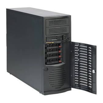
Overview The Supermicro SuperWorkstation 7034A-T/7034A-i is a high-end, dual proces- sor workstation in a tower configuration. The 7034A-T/7034A-i is comprised of two main subsystems: the SC733T-645/SC733i-645 high-end server chassis and the X6DAL-TG/X6DAL-G Intel to our web site for information on operating systems that have been certified for use with the SuperWorkstation 7034A-T/7034A-i. -
Page 12: Serverboard Features
UPER ORKSTATION 7034A-T/7034A-i Manual Serverboard Features At the heart of the SuperWorkstation 7034A-T/7034A-i lies the X6DAL-TG/ X6DAL-G, a dual processor serverboard based on the Intel E7525 chipset and designed to provide maximum performance. Below are the main fea- tures of the X6DAL-TG/X6DAL-G. (See Figure 1-1 for a block diagram of the E7525 chipset). -
Page 13: Server Chassis Features
CPU overheat sensors, virus protection and BIOS rescue. Server Chassis Features The SuperWorkstation 7034A-T/7034A-i is a high-end, scaleable tower plat- form designed with today's most state-of-the-art features. The following is a general outline of the main features of the SC733T-645/SC733i-645 chas- sis. -
Page 14: System Block Diagram
UPER ORKSTATION 7034A-T/7034A-i Manual Note: the 4-pin fan headers on the 7034A-T/7034A-i serverboard may present some confusion to users who decide to add CPU heatsinks that have 3-pin fan headers. Heatsinks with 3-pin fan headers may be connected to the serverboard, but these fans will not be controlled by PWM and will constantly run at full speed, which may generate too much noise for the workspace. -
Page 15: Contacting Supermicro
Contacting Supermicro Headquarters Address: SuperMicro Computer, Inc. 980 Rock Ave. San Jose, CA 95131 U.S.A. Tel: +1 (408) 503-8000 Fax: +1 (408) 503-8008 Email: marketing@supermicro.com (General Information) support@supermicro.com (Technical Support) Web Site: www.supermicro.com Europe Address: SuperMicro Computer B.V. Het Sterrenbeeld 28, 5215 ML... - Page 16 UPER ORKSTATION 7034A-T/7034A-i Manual Notes...
-
Page 17: Chapter 2: Server Installation
2-1 Overview This chapter provides a quick setup checklist to get your SuperWorkstation 7034A-T/7034A-i up and running. Following these steps in the order given should enable you to have the system operational in a minimal amount of time. This quick setup assumes that your SuperWorkstation 7034A-T/7034A-i system has come to you with the processors and memory preinstalled. -
Page 18: Checking The Serverboard Setup
Allow the power supply unit and the SATA hard drives (7034A-T only) to cool before touching them. Always keep the chassis front door and all panels closed when not ser- vicing to maintain proper cooling. - Page 19 5. Check all cable connections and airflow Make sure all power and data cables are properly connected and not blocking the chassis airflow. See Chapter 5 for details on cable connec- tions. Figure 2-1. Accessing the Inside of the 7034A-T/7034A-i...
-
Page 20: Checking The Drive Bay Setup
4. Check the SATA/IDE disk drives Depending upon your the configuration, your system may have one or more SATA (7034A-T) or IDE (7034A-i) hard drives already installed. If you need to install an SATA or IDE hard drive, please refer to Chapter 6. -
Page 21: Chapter 3: System Interface
Overview There are several LEDs on the control panel to keep you constantly informed of the overall status of the system and the activity and health of specific components. There are also two buttons on the chassis control panel. Control Panel Buttons There are two push buttons located on the front of the chassis. -
Page 22: Control Panel Leds
UPER ORKSTATION 7034A-T/7034A-i Manual Control Panel LEDs The control panel located on the front of the SC733T-645/SC733i-645 chassis has four LEDs that provide you with critical information related to different parts of the system. This section explains what each LED indicates when illuminated and any corrective action you may need to take. -
Page 23: Lan (Ethernet) Port Leds
LAN (Ethernet) Port LEDs The LAN port has a yellow and a green LED. The yellow (left) LED indicates activity while the other (right) LED may be green, orange or off to indicate the speed of the connection. See the tables below for the functions associated with these LEDs. - Page 24 UPER ORKSTATION 7034A-T/7034A-i Manual Notes...
-
Page 25: Chapter 4: System Safety
Electrical Safety Precautions Basic electrical safety precautions should be followed to protect yourself from harm and the SuperWorkstation 7034A-T/7034A-i from damage: Be aware of the locations of the power on/off switch on the chassis as well as the room's emergency power-off switch, disconnection switch or electrical outlet. -
Page 26: General Safety Precautions
General Safety Precautions Follow these rules to ensure general safety: Keep the area around the SuperWorkstation 7034A-T/7034A-i clean and free of clutter. The SuperWorkstation 7034A-T/7034A-i weighs approximately 40 lbs. When lifting the system, two people at either end should lift slowly with their feet spread out to distribute the weight. -
Page 27: Esd Safety Precautions
where power is present. After accessing the inside of the system, close the system back up and (if rackmounted) secure it to the rack unit with the retention screws after ensuring that all connections have been made. ESD Precautions Electrostatic discharge (ESD) is generated by two objects with different electrical charges coming into contact with each other. -
Page 28: Operating Precautions
Operating Precautions Care must be taken to assure that all chassis covers are in place when the 7034A-T/7034A-i is operating to ensure proper cooling. Out of warranty damage to the 7034A-T/7034A-i system can occur if this practice is not strictly followed. -
Page 29: Chapter 5: Advanced Serverboard Setup
Advanced Serverboard Setup This chapter covers the steps required to install processors and heatsinks to the X6DAL-TG/X6DAL-G serverboard, connect the data and power cables and install add-on cards. All serverboard jumpers and connections are described and a layout and quick reference chart are included in this chapter. Remember to close the chassis completely when you have finished working on the serverboard to protect and cool the system sufficiently. -
Page 30: Processor And Heatsink Installation
UPER ORKSTATION 7034A-T/7034A-i Manual Processor and Heatsink Installation When handling the processor package, avoid placing direct pressure on the label area of the fan. Also, do not place the serverboard on a conductive surface, which can damage the BIOS battery and prevent the system from booting up. - Page 31 Heatsink Installation* 1. Do not apply any thermal com- pound to the heatsink or the CPU die; the required amount has al- ready been applied. 2. Place the heatsink on top of the CPU so that the four mounting holes are aligned with those on the retention mechanism.
- Page 32 UPER ORKSTATION 7034A-T/7034A-i Manual Removing the Heatsink/CPU IMPORTANT: Removal of the heatsink or the CPU is not recom- mended. However, if you do need to remove the heatsink, please follow the instructions below to prevent damaging the CPU or the CPU socket.
-
Page 33: Connecting Cables
The following data cables (with their serverboard connector locations noted) should be connected. See the serverboard layout figure in this chapter for connector locations. SATA drive cable (J52-J55, 7034A-T) IDE drive cable (JA1, 7034A-i) Control Panel cable (JF1, see next page) -
Page 34: Connecting The Control Panel
UPER ORKSTATION 7034A-T/7034A-i Manual Connecting the Control Panel JF1 contains header pins for various front control panel connectors. See Figure 5-2 for the pin locations of the various front control panel buttons and LED indicators. Please note that even and odd numbered pins are on opposite sides of each header. -
Page 35: I/O Ports
Figure 5-3 below for the colors and locations of the various I/O ports. Figure 5-3. Rear Panel I/O Ports Installing Memory Note: Check the Supermicro web site for recommended memory modules: http://www.supermicro.com/TECHSUPPORT/FAQs/Memory_vendors.htm Exercise extreme care when installing or removing DIMM modules to prevent any possible damage. - Page 36 UPER ORKSTATION 7034A-T/7034A-i Manual Memory Support The X6DAL-TG/X6DAL-G supports up to 12/24 GB of registered ECC DDR333/266 (PC2700/PC2100) SDRAM memory. The serverboard was designed to support 4 GB DDR266 modules in each slot but has only been verified with 2 GB modules.
-
Page 37: Adding Pci Cards
Adding PCI Cards PCI slots: The X6DAL-TG/X6DAL-G has six PCI expansion slots, which includes one PCI-Express x16 slot, one PCI-Express x8 slot, two PCI-X 66 MHz slots and two 32-bit 33MHz PCI slots. The SC733T-645/SC733i-645 chassis allows all six slots to be populated. PCI card installation: Before installing a PCI add-on card, make sure you install it into a slot that supports the speed of the card (see step 1, above). -
Page 38: Serverboard Details
UPER ORKSTATION 7034A-T/7034A-i Manual Serverboard Details Figure 5-6. SUPER X6DAL-TG/X6DAL-G Layout* ATX PWR Force PW-On Fault DIMM 1B DIMM 1A DIMM 2B DIMM 2A DIMM 3B DIMM 3A J 4 3 J F 2 Spkr *Notes: Jumpers not noted are for test purposes only. -
Page 39: X6Dal-Tg/X6Dal-G Quick Reference
X6DAL-TG/X6DAL-G Quick Reference Jumper Description Alarm Reset SMB Data to PCI Enable/Disable SMB Clock to PCI Enable/Disable Audio Enable/Disable JBT1 CMOS Clear Force Power On Enable/Disable JPL1 LAN1 Enable/Disable JPS1* SATA Controller Enable/Disable Watch Dog Connector Description ATX PWR Primary 24-pin ATX PWR Connector DIMM#1A-#3B Memory (DIMM) Slots DS7/DS8... -
Page 40: Connector Definitions
UPER ORKSTATION 7034A-T/7034A-i Manual Connector Definitions ATX Power Connector The X6DAL-TG/X6DAL-G includes a 24-pin main power supply connector (PW1) and a 4-pin CPU PWR con- nector (PWR3). Both connections are required. These power connec- tors meet the SSI EPS 12V specifi- cation. -
Page 41: Hdd Led
HDD LED The HDD LED connection is located on pins 13 and 14 of JF1. Attach the hard drive LED cable to these pins to display hard disk drive activity. Re- fer to the table on the right for pin definitions. -
Page 42: Reset Button
UPER ORKSTATION 7034A-T/7034A-i Manual Reset Button The Reset Button connection is lo- cated on pins 3 and 4 of JF1. Attach it to the hardware reset switch on the computer case. Refer to the table on the right for pin definitions. -
Page 43: Fan Headers
Fan Headers There are six fan headers (FAN1- FAN6) on the X6DAL-TG/X6DAL-G. See the table on the right for pin defi- nitions. Note: These fan headers are 4-pin fans. Pins#1-#3 of the fan headers are backward compatible with tradi- tional 3-pin fans. Fan speed is con- trolled by Thermal Management via a Hardware Monitor and BIOS (Ad- vanced Setting) -
Page 44: Power Led/Speaker/Keylock
UPER ORKSTATION 7034A-T/7034A-i Manual Power LED/Speaker/Keylock On the JF2 header, pins 1, 3, 5 and 7 are for the speaker, pins 2, 4 and 6 are for the power LED and pins 8 and 9 are for the keylock. See the table on the right for speaker pin definitions. -
Page 45: Power Fault
Definition P/S 1 Fail Signal P/S 2 Fail Signal P/S 3 Fail Signal Reset (from MB) Note: This feature is only available when using redundant Supermicro power supplies. SATA SMB (J35) Pin Definitions Number Definition SMB PWR Pin Definitions (J27) -
Page 46: Jumper Settings
UPER ORKSTATION 7034A-T/7034A-i Manual Jumper Settings Explanation of Jumpers To modify the operation of the serverboard, jumpers can be used choose optional settings. create shorts between two pins to change the function of the connector. Pin 1 is identified with a square solder pad on the printed circuit board. -
Page 47: Glan Enable/Disable
The default setting is enabled. Alarm Reset The system will notify you in the event of a power supply failure. This feature assumes that Supermicro redundant power supply units are installed in the chassis. If you only have a single power supply installed,... -
Page 48: Watch Dog Enable/Disable
UPER ORKSTATION 7034A-T/7034A-i Manual Watch Dog Enable/Disable JWD enables the Watch Dog func- tion. Watch Dog is a system moni- tor that can reboot the system when a software application is "hung up". Pins 1-2 will cause WD to reset the system if an application is hung up. -
Page 49: 5-10 Onboard Indicators
5-10 Onboard Indicators LAN LEDs The Ethernet port has two LEDs. The yellow LED indicates activity while the other LED may be green, orange or off to indicate the speed of the connection. See the table on the right for the functions associated with this second LED. -
Page 50: 5-11 Floppy And Hard Disk Drive Connections
UPER ORKSTATION 7034A-T/7034A-i Manual 5-11 Floppy and Hard Disk Drive Connections Note the following when connecting the floppy and hard disk drive cables: • The floppy disk drive cable has seven twisted wires. • A red mark on a wire typically designates the location of pin 1. -
Page 51: Ide Connectors
IDE Connectors There are no jumpers to configure the onboard IDE#1 and #2 connectors. See the table on the right for pin definitions. Chapter 5: Advanced Serverboard Setup IDE Connector Pin Definitions (IDE1, IDE2) Pin Number Function Pin Number Reset IDE Host Data 7 Host Data 6 Host Data 5... - Page 52 UPER ORKSTATION 7034A-T/7034A-i Manual Notes 5-24...
-
Page 53: Chapter 6: Advanced Chassis Setup
Advanced Chassis Setup This chapter covers the steps required to install components and perform simple maintenance on the SC733T-645/SC733i-645 chassis. Following the component installation steps in the order given will eliminate most common problems. If some steps are unnecessary, skip ahead to the next step. Tools Required The only tool you will need is a Philips screwdriver. -
Page 54: Front Control Panel
UPER ORKSTATION 7034A-T/7034A-i Manual Front Control Panel The front control panel must be connected to the JF1 connector on the serverboard to provide you with system status and alarm indications. A ribbon cable has bundled these wires together to simplify this connection. Connect the cable from JF1 on the serverboard (making sure the red wire plugs into pin 1) to the appropriate connector on the front control panel PCB (printed circuit board). - Page 55 Figure 6-2. Chassis Front View 7034A-T 5.25" Drive Bays Floppy Drive Bay Main Power System Reset Front Side USB System LEDs Front Bezel Lock (7034A-T only) 9-cm Fan Bay (inside chassis) Chapter 6: Advanced Chassis Setup 7034A-i...
- Page 56 UPER ORKSTATION 7034A-T/7034A-i Manual Figure 6-3. Chassis Rear View Power Supply Power Supply Fan I/O Backplane 12-cm Exhaust Fan PCI Expansion Slots...
-
Page 57: System Fans
Installing a new system fan Disassemble the housing and replace the failed fan with an identical one (available from Supermicro). After the new fan has been installed, reas- semble the fan housing and install it by reversing the removal procedure. - Page 58 UPER ORKSTATION 7034A-T/7034A-i Manual Figure 6-4. Removing the 12-cm Exhaust Fan Figure 6-5. Removing the 9-cm Chassis Fan...
-
Page 59: Drive Bay Installation
Drive Bay Installation 7034A-T: A swinging bezel covers the front of the chassis but does not need to be removed to access the drives. simply unlock the bezel and swing it open. 7034A-i: The bezel that covers the front of the chassis must be removed to access the drives. - Page 60 UPER ORKSTATION 7034A-T/7034A-i Manual Mounting a SATA drive in a drive carrier: The SATA drives are mounted in drive carriers to simplify their installation and removal from the chassis. These carriers also work to promote proper airflow for the system.
- Page 61 SATA backplane: All four SATA drives plug into the SATA backplane. There are two jumpers and two headers on the SATA backplane, as noted below. A ribbon cable from JA1 on the serverboard should be connected to the JP26 connector on the SATA backplane. There are also two power connectors on the backplane - both should be connected.
-
Page 62: Installing Components In The 5.25" Drive Bays
Installing Components in the 5.25" Drive Bays Drive bay configuration The 7034A-T/7034A-i has two empty 5.25" drive bays above the SATA/IDE drive bays. Components such as a floppy drive, IDE hard drives or CD-ROM drives can be installed in these 5.25" drive bays. -
Page 63: Power Supply
Power Supply The 7034A-T/7034A-i has a single 645W redundant cooling power supply (part# PWS-0060) that features noise-suppression technology for silent operation. The power supply has the capability to automatically sense and operate at 100 - 240V AC. This power supply also has PFC (Power Factor Correction) built in. - Page 64 UPER ORKSTATION 7034A-T/7034A-i Manual Notes 6-12...
-
Page 65: Chapter 7: Bios
When an option is selected in the left frame, it is highlighted in white. Often a text message will accompany it. (Note: The AMI BIOS has default text messages built in. Supermicro retains the option to include, omit, or change any of these text messages.) The AMI BIOS setup/utility uses a key-based navigation system called hot keys. -
Page 66: 7-2 Main Setup
UPER ORKSTATION 7034A-T/7034A-i Manual 7-2 Main Setup When you first enter the AMI BIOS Setup Utility, you will enter the Main setup screen. You can always return to the Main setup screen by selecting the Main tab on the top of the screen. The Main BIOS Setup screen is shown below. -
Page 67: Advanced Settings
Chapter 7: BIOS System Memory This option allows the AMI BIOS to display the status of memory installed in the system. Size This option allows the AMI BIOS to display the size of memory installed in the system. System Time/System Date Use this option to change the system time and date. - Page 68 UPER ORKSTATION 7034A-T/7034A-i Manual CPU Configuration Sub Menu Configure Advanced CPU Settings This option allows the user to configure Advanced CPU settings for the processor(s) installed in the system. Ratio CMOS Setting This option allows the user to set the ratio between the CPU Core Clock and the FSB Frequency.
- Page 69 IDE Configuration Sub Menu The screen for the Primary IDE Master is shown below: When you select this Sub Menu, the AMI BIOS automatically displays the status of the following items: Onboard PCI IDE Operate Mode This feature allows the user to set the Onboard PCI IDE Operation Mode. The options are: Native Mode and Legacy Mode.
- Page 70 UPER ORKSTATION 7034A-T/7034A-i Manual S-ATA Ports Definition This feature allows the user to configure Serial ATA Ports. The options are: P0-Master/P1-Slave, P0-Slave/P1-Master P-ATA Only S-ATA Running Enhanced Mode Select Yes if you want the function of Serial ATA Enanced Mode to be enabled at all times.
- Page 71 Chapter 7: BIOS LBA/Large Mode LBA (Logical Block Addressing) is a method of addressing data on a disk drive. In the LBA mode, the maximum drive capacity is 137 GB. For drive capacities over 137 GB, your system must be equipped with 48-bit LBA mode addressing.
- Page 72 UPER ORKSTATION 7034A-T/7034A-i Manual to allow the BIOS to use Single Word DMA mode 0. It has a data transfer rate of 2.1 MBs. Select SWDMA1 to allow the BIOS to use Single Word DMA mode 1. It has a data transfer rate of 4.2 MBs. Select SWDMA2 to allow the BIOS to use Single Word DMA mode 2.
-
Page 73: Floppy Configuration
Chapter 7: BIOS ATA(PI) 80Pin Cable Detection This feature allows the AMI BIOS to auto-detect 80Pin ATA(PI) Cable. The options are: Host & Device, Host and Device. Floppy Configuration This option allows the user to configure the settings for the Floppy Drives installed in the system. - Page 74 UPER ORKSTATION 7034A-T/7034A-i Manual PCI/PnP Configuration This feature allows the user to set PCI/PnP configurations for the following items: Plug & Play OS Select Yes to allow the OS to configure Plug & Play devices. (*This is not required for system boot if you system has an OS that supports Plug &...
- Page 75 Chapter 7: BIOS IRQ3/IRQ4/IRQ5/IRQ7/IRQ9/IRQ10/IRQ11/IRQ14 This feature specifies the availability of an IRQ to be used by a PCI, PnP device. Select Reserved for the IRQ to be used by a Legacy ISA device. The options are: Available, Reserved. DMA Channel 0/DMA Channel 1/DMA Channel 3/DMA Channel 5/ DMA Channel 6/DMA Channel 7 Select Available to indicate that a specific DMA channel is available to be used by a PCI/PnP device.
-
Page 76: Advanced Chipset Settings
UPER ORKSTATION 7034A-T/7034A-i Manual Serial Port1 Address This option specifies the base I/O port address and Interrupt Request ad- dress of serial port 1. accessing any system resources. When this option is set to Disabled, the serial port physically becomes unavailable. Select "3F8/IRQ4" to allow the serial port to use 3F8 as its I/O port address and IRQ 4 for the interrupt address. - Page 77 NorthBridge Configuration This feature allows the user to configure the settings for Intel Lindenhurst NorthBridge chipset. Memory Remap Feature Select Enabled to allow remapping of overlapped PCI memory above the total physical memory. The options are Enabled and Disabled. Memory Mirroring and Sparing Select Enabled to enable Memory RAS (-Mirroring and Sparing) to allow the system to create a mirror copy of data written to the memory for data security.
- Page 78 UPER ORKSTATION 7034A-T/7034A-i Manual APCI Configuration This item allows the user to enable or disable ACPI support for the operating system. General ACPI Configuration Use this feature to configure additional ACPI options. Select "Yes" if the operating system supports ACPI. Select No if the operating system does not support ACPI.
-
Page 79: Power Configuration
Power Configuration This feature allows the user to configure PnP settings. Power Button Mode This setting allows you to decide if the power button will go into the On/ Off mode or the Suspend mode if it is pressed. The and Suspend. - Page 80 UPER ORKSTATION 7034A-T/7034A-i Manual Memory Buffer Event Logging This setting allows you to enable or disable Memory Buffer Event logging. The options are Enabled or Disabled. PCI Error Logging This setting allows you to enable or disable PCI Error logging. The options are Enabled or Disabled.
-
Page 81: Usb Configuration
Spread Spectrum Select Enabled to enable Spread Sperctrum. The options are Disabled and Enabled. Remote Access Configuration You can use this screen to select options for the Remote Access Configu- ration. Use the up and down <Arrow> keys to select an item. Use the <Plus>... -
Page 82: System Health Monitor
UPER ORKSTATION 7034A-T/7034A-i Manual USB 2.0 Controller Mode This setting allows you to configure USB 2.0 Controller Mode. The options are Hi-Speed (480 Mbps) or Full Speed-12Mbps. System Health Monitor This feature allows the AMI BIOS to automatically display the status of the... - Page 83 The options are "Disable", "3-pin (Server)", "3-pin (Workstation)", "4-pin (Server)" and "4-pin (Workstation)". The recommended setting for the 7034A-T/7034A-i is "4-pin (Workstation)". Note: loading the default settings into BIOS may change this setting. If you do load BIOS defaults, you should reenter BIOS setup and change this setting back to "4-pin (Workstation)", then save and exit.
- Page 84 UPER ORKSTATION 7034A-T/7034A-i Manual Boot Settings Configuration This item allows the user to configure the boot settings for the system. Quick Boot Select Enabled to allow theh AMI BIOS to skip certain test during POST in order to shorten the time needed for the system to bootup. The options are Enabled, and Disabled.
- Page 85 Chapter 7: BIOS Boot up Num-Lock Set this value to allow the Number Lock setting to be modified during boot up. The default setting is On. The options are On and Off. PS/2 Mouse Support Set this value to allow the PS/2 mouse support to be modified. The options are Auto, Enabled and Disabled.
-
Page 86: Boot Device Priority
UPER ORKSTATION 7034A-T/7034A-i Manual Boot Device Priority This feature allows the user to specify the sequence of priority for the Boot Device. The settings are "1st Floppy Drive", "CD ROM", "HDD", and "Disabled." The default settings are: · 1st boot device –1st Floppy Drive ·... -
Page 87: Security Settings
Chapter 7: BIOS Security Settings the AMI BIOS provides a Supervisor and a User password. If you use both passwords, the Supervisor password must be set first. Change Supervisor Password Select this option and press <Enter> to access the sub menu, and then, type in the password. -
Page 88: Exit Options
UPER ORKSTATION 7034A-T/7034A-i Manual Exit Options Select the Exit tab from the AMI BIOS Setup Utility screen to enter the Exit the BIOS Setup screen. Saving Changes and Exit When you have completed the system configuration changes, select this option to leave the BIOS Setup and reboot system configuration parameters can take effect. - Page 89 Chapter 7: BIOS Load Optimal Defaults To set this feature, select Load Optimal Defaults from the Exit menu and press <Enter>. Then, Select "OK" to allow the BIOS to automatically load Optimal Defaults to the BIOS Settings. The Optimal settings are designed for maximum system performance, but may not work best for all computer ap- plications.
- Page 90 UPER ORKSTATION 7034A-T/7034A-i Manual Notes 7-26...
- Page 91 BIOS Error Beep/POST Codes During the POST (Power-On Self-Test) routines, which are performed each time the system is powered on, errors may occur. Non-fatal errors are those which, in most cases, allow the system to continue the boot-up process. The error messages normally appear on the screen.
- Page 92 UPER ORKSTATION 7034A-T/7034A-i Manual DS7/DS8 LED POST Codes LED Indicators DS7 DS8 Off On Off Off Description/Message PWR On SPD Read OK Memory Size-OK Starting Bus Initialization...
-
Page 93: Appendix B: Bios Post Checkpoint Codes
BIOS POST Checkpoint Codes When AMIBIOS performs the Power On Self Test, it writes checkpoint codes to I/O port 0080h. If the computer cannot complete the boot process, diagnostic equipment can be attached to the computer to read I/O port 0080h. Uncompressed Initialization Codes The uncompressed initialization checkpoint codes are listed in order of execution: Checkpoint... - Page 94 UPER ORKSTATION 7034A-T/7034A-i Manual Bootblock Recovery Codes The bootblock recovery checkpoint codes are listed in order of execution: Checkpoint Code Description The onboard floppy controller if available is initialized. Next, beginning the base 512 KB memory test. Initializing the interrupt vector table next.
- Page 95 initialization before the keyboard BAT command is issued. The keyboard controller input buffer is free. Next, issuing the BAT command to the keyboard controller. The keyboard controller BAT command result has been verified. Next, performing any necessary initialization after the keyboard controller BAT command test.
- Page 96 UPER ORKSTATION 7034A-T/7034A-i Manual Checkpoint Code Description Interrupt vector initialization is done. Clearing the password if the POST DIAG switch is on. Any initialization before setting video mode will be done next. Initialization before setting the video mode is complete. Configuring the monochrome mode and color mode settings next.
- Page 97 Checkpoint Code Description Patterns written in base memory. Determining the amount of memory below 1 MB next. The amount of memory below 1 MB has been found and verified. Determining the amount of memory above 1 MB memory next. The amount of memory above 1 MB has been found and verified. Checking for a soft reset and clearing the memory below 1 MB for the soft reset next.
- Page 98 UPER ORKSTATION 7034A-T/7034A-i Manual Checkpoint Code Description The DMA page register test passed. Performing the DMA Controller 1 base register test next. The DMA controller 1 base register test passed. Performing the DMA controller 2 base register test next. The DMA controller 2 base register test passed. Programming DMA controllers 1 and 2 next.
- Page 99 Checkpoint Code Description Initializing the bus option ROMs from C800 next. See the last page of this chapter for additional information. Initializing before passing control to the adaptor ROM at C800. Initialization before the C800 adaptor ROM gains control has com- pleted.
- Page 100 UPER ORKSTATION 7034A-T/7034A-i Manual Notes...
-
Page 101: Appendix C: System Specifications
Single or dual 604-pin Intel Xeon processors at a front side (system) bus speed of 800 MHz. (Please refer to the support section of our web site for a complete listing of supported processors: www.supermicro.com). Chipset Intel E7525 chipset BIOS ®... - Page 102 UPER ORKSTATION 7034A-T/7034A-i Manual Serverboard (7034A-T/7034A-i) Model: X6DAL-TG/X6DAL-G (Extended ATX) Dimensions: 12 x 10 in (305 x 254 mm) Chassis (7034A-T/7034A-i) Model: SC733T-645/SC733i-645 (tower) Dimensions: (WxHxD) 6.94" x 17.125 x 24.125 in. (17.6 x 435 x 612.8 Weight Gross (Bare Bone): 40 lbs. (18.2 kg.) System Cooling (all fan speed controlled by BIOS setting: p.
- Page 103 Appendix C: System Specifications Safety: EN 60950/IEC 60950-Compliant UL Listed (USA) CUL Listed (Canada) TUV Certified (Germany) CE Marking (Europe)
- Page 104 UPER ORKSTATION 7034A-T/7034A-i Manual Notes...