Table of Contents
Advertisement
Quick Links
Advertisement
Table of Contents

Related Manuals for Supermicro 5038K-i


Summary of Contents for Supermicro 5038K-i
- Page 1 5038K-i User's Manual Revision 1.0...
- Page 2 This product, including software and documentation, is the property of Supermicro and/or its licensors, and is supplied only under a license. Any use or reproduction of this product is not allowed, except as expressly permitted by the terms of said license.
-
Page 3: About This Manual
K1SPE motherboard and the GS5A-753B chassis. Chapter 2: System Installation This chapter describes the steps necessary to setup the 5038K-i and check out the system confi guration prior to powering up the system. Chapter 3: System Interface... - Page 4 5038K-i User's Manual Chapter 7: BIOS The BIOS chapter includes an introduction to BIOS and provides detailed information on running the CMOS Setup Utility. Appendix A: BIOS Error Beep Codes Appendix B: System Specifi cations...
- Page 5 Preface Notes...
-
Page 6: Table Of Contents
5038K-i User's Manual Table of Contents Chapter 1 Introduction Overview ......................1-1 Motherboard Features ..................1-2 Processors ...................... 1-2 Memory ......................1-2 SATA ......................1-2 PCI Expansion Slots ..................1-3 Onboard Controllers/Ports ................1-3 Other Features ....................1-3 Recovery from AC Power Loss ............... 1-4 PC Health Monitoring .................. - Page 7 Table of Contents Chapter 3 System Interface Overview ......................3-1 Control Panel Button ..................3-1 Power ......................3-1 Reset ....................... 3-1 Front Panel Components ................3-2 Chapter 4 Standardized Warning Statements for AC Systems About Standardized Warning Statements ............4-1 Warning Defi...
- Page 8 5038K-i User's Manual 5-10 Installing Drivers .................... 5-22 SuperDoctor 5 ....................5-23 5-11 Motherboard Battery ..................5-24 Chapter 6 Advanced Chassis Setup Static-Sensitive Devices .................. 6-1 Precautions ..................... 6-1 Removing Power from the System ..............6-2 Accessing the Inside of the System..............6-2 Left Side and Right Side Covers ..............
-
Page 9: Chapter 1 Introduction
Chapter 1 Introduction Overview The 5038K-i is a high-end workstation comprised of two main subsystems: the GS5A-753B mid-tower chassis and the K1SPE single Intel® processor motherboard. Please refer to our web site for information on operating systems that have been certifi... -
Page 10: Motherboard Features
5038K-i User's Manual Motherboard Features At the heart of the 5038K-i lies the K1SPE, a single processor motherboard based on the Intel® PCH C612 chipset. Below are the main features of the K1SPE. (See Figure 1-1 for a block diagram of the chipset). -
Page 11: Pci Expansion Slots
Chapter 1: Introduction PCI Expansion Slots The K1SPE has the following available expansion ports on the motherboard: • Two (2) PCI Express 3.0 x16 slots (CPU Slot4/Slot6) • One (1) PCI Express 2.0 x4 (in x8) slot (PCH Slot2) Onboard Controllers/Ports Both the motherboard and chassis include the following I/O ports: •... -
Page 12: Recovery From Ac Power Loss
5038K-i User's Manual • LED Indicators for: CPU/system overheat LED, Power/suspend state indicator, Fan failure LED, LAN activity LED, BMC (BaseBoard Management) LED and UID/Remote UID LED • System resource alert via SuperDoctor® 5 • SuperDoctor® 5, Watch Dog, NMI, SPM, SUM-InBand, SUM-OOB... -
Page 13: System Resource Alert
Chapter 1: Introduction System Resource Alert This feature is available when the system is used with SuperDoctor 5 in the Windows OS environment. SuperDoctor is used to notify the user of certain system events. For example, you can also confi gure SuperDoctor to provide you with warnings when the system temperature, CPU temperatures, voltages and fan speeds go beyond predefi... -
Page 14: Super I/O
Large motherboard tray cut-out for CPU cooler back-plates System Power The 5038K-i features a single 750 Watt power supply. This power supply unit has been designed to operate at a low noise level to make it ideal for use in a noise... -
Page 15: Hard Drives
Chapter 1: Introduction Hard Drives The 5038K-i standard confi guration includes two 5.25" drive bays, four 2.5" drive bays, and six combination bays that can house either 3.5" or 2.5" drives. • Each 5.25" bay can be confi gured to accept a 3.5"drive, or one or two 2.5" drives (with optional bracket (MCP-220-00044-ON)). -
Page 16: System Block Diagram
5038K-i User's Manual Figure 1-1. Intel PCH C612 Chipset: System Block Diagram Note: This is a general block diagram. Please see Chapter 5 for details. Processor DMI2 SLOT 4 PCIe X16 G3 PCI-E X16 DMI2 4GB/s SLOT 6 LAN2 MDI... -
Page 17: Contacting Supermicro
Super Micro Computer, Inc. 980 Rock Ave. San Jose, CA 95131 U.S.A. Tel: +1 (408) 503-8000 Fax: +1 (408) 503-8008 Email: marketing@supermicro.com (General Information) support@supermicro.com (Technical Support) Website: www.supermicro.com Europe Address: Super Micro Computer B.V. Het Sterrenbeeld 28, 5215 ML... - Page 18 5038K-i User's Manual Notes 1-10...
-
Page 19: Chapter 2 Installation
Installation Overview This chapter provides a quick setup checklist to get your 5038K-i up and running. Following these steps in the order given should enable you to have the system operational within a minimum amount of time. This quick setup assumes that your system has come to you with the motherboard pre-installed. -
Page 20: Accessing The Inside Of The System
5038K-i User's Manual Accessing the Inside of the System You may need to access the system periodically to perform maintenance or install components such as hard drives. The system features two removable side covers, allowing easy access to the system interior. -
Page 21: Front Bezel
Chapter 2: Installation Front Bezel Remove the front bezel by pulling it off from the bottom of the bezel. Figure 2-2. Removing the Front Bezel... - Page 22 5038K-i User's Manual Notes...
-
Page 23: Chapter 3 System Interface
Chapter 3 System Interface Overview The control panel on the 5038K-i has one LED, a power button and a reset button. This LED keeps you constantly informed of hard drive status and activity. Control Panel Button A single push-button is located on the front of the chassis. -
Page 24: Front Panel Components
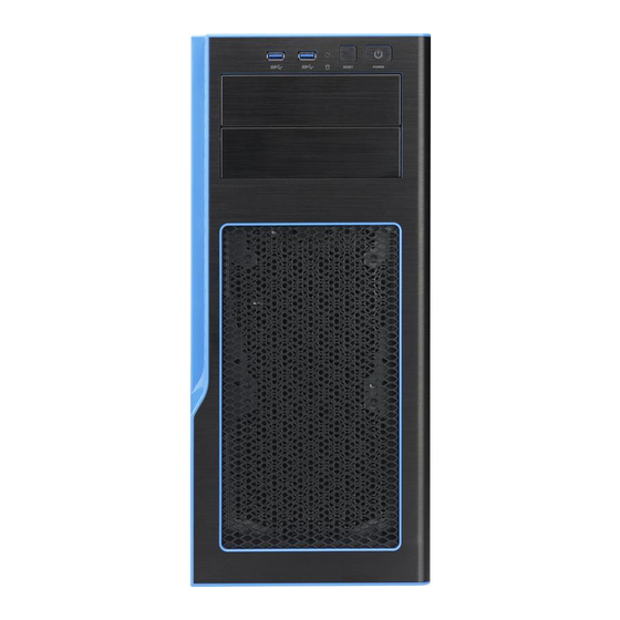
5038K-i User's Manual Front Panel Components The 5038K-i features a front panel allowing easy access to the chassis power and communication ports. In addition to the Power and Reset buttons, two USB 3.0 ports are also provided on the Front Panel. An LED indicates activity for the HHD. -
Page 25: Chapter 4 Standardized Warning Statements For Ac Systems
The following statements are industry standard warnings, provided to warn the user of situations which have the potential for bodily injury. Should you have questions or experience difficulty, contact Supermicro's Technical Support department for assistance. Only certifi ed technicians should attempt to install or confi gure components. - Page 26 5038K-i User's Manual Warnung WICHTIGE SICHERHEITSHINWEISE Dieses Warnsymbol bedeutet Gefahr. Sie befi nden sich in einer Situation, die zu Verletzungen führen kann. Machen Sie sich vor der Arbeit mit Geräten mit den Gefahren elektrischer Schaltungen und den üblichen Verfahren zur Vorbeugung vor Unfällen vertraut.
- Page 27 Warning Statements for AC Systems ﺟﺴﺪﯾﺔ اﺻﺎﺑﺔ ﺗﺘﺴﺒﺐ ﻓﻲ ﺣﺎﻟﺔ ﯾﻤﻜﻦ أن اﻧﻚ ﻓﻲ ﺧﻄﺮ ﯾﻌﻨﻲ ھﺬا اﻟﺮﻣﺰ !ﺗﺤﺬﯾﺮ اﻟﺪواﺋﺮ ﺑﺎﻟﻤﺨﺎطﺮ اﻟﻨﺎﺟﻤﺔ ﻋﻦ ﻦ ﻋﻠﻰ ﻋﻠﻢ ، ﻛ ﻣﻌﺪات ﺗﻌﻤﻞ ﻋﻠﻰ أي ﻗﺒﻞ أن اﻟﻜﮭﺮﺑﺎﺋﯿﺔ ﺣﻮادث أي وﻗﻮع ﻤﻨﻊ ﻟ اﻟﻮﻗﺎﺋﯿﺔ...
-
Page 28: Installation Instructions
5038K-i User's Manual Installation Instructions Warning! Read the installation instructions before connecting the system to the power source. 設置手順書 システムを電源に接続する前に、 設置手順書をお読み下さい。 警告 将此系统连接电源前,请先阅读安装说明。 警告 將系統與電源連接前,請先閱讀安裝說明。 Warnung Vor dem Anschließen des Systems an die Stromquelle die Installationsanweisungen lesen. ¡Advertencia! Lea las instrucciones de instalación antes de conectar el sistema a la red de alimentación. -
Page 29: Circuit Breaker
Chapter 4: Warning Statements for AC Systems Circuit Breaker Warning! This product relies on the building's installation for short-circuit (overcurrent) protection. Ensure that the protective device is rated not greater than: 250 V, 20 A. サーキッ ト ・ ブレーカー この製品は、 短絡 (過電流) 保護装置がある建物での設置を前提としています。 保護装置の定格が250 V、... -
Page 30: Power Disconnection Warning
5038K-i User's Manual ﻓﻲ اﻟﺘﻲ ﺗﻢ ﺗﺜﺒﯿﺘﮭﺎ ﻣﻦ اﻟﺪواﺋﺮاﻟﻘﺼﯿﺮة اﻟﺤﻤﺎﯾﺔ ﻣﻌﺪات ﯾﻌﺘﻤﺪ ﻋﻠﻰ ھﺬا اﻟﻤﻨﺘﺞ اﻟﻤﺒﻨﻰ أﻛﺜﺮ ﻣﻦ ﻟﯿﺲ ﻮﻗﺎﺋﻲ اﻟ اﻟﺠﮭﺎز ﺗﻘﯿﯿﻢ أن ﺗﺄﻛﺪ ﻣﻦ 20A, 250V 경고! 이 제품은 전원의 단락(과전류)방지에 대해서 전적으로 건물의 관련 설비에 의존합니다. 보호장치의 정격이 반드시 250V(볼트), 20A(암페어)를 초과하지... - Page 31 Chapter 4: Warning Statements for AC Systems Warnung Das System muss von allen Quellen der Energie und vom Netzanschlusskabel getrennt sein, das von den Spg.Versorgungsteilmodulen entfernt wird, bevor es auf den Chassisinnenraum zurückgreift, um Systemsbestandteile anzubringen oder zu entfernen. ¡Advertencia! El sistema debe ser disconnected de todas las fuentes de energía y del cable eléctrico quitado de los módulos de fuente de alimentación antes de tener acceso el interior del chasis para instalar o para quitar componentes de sistema.
-
Page 32: Equipment Installation
5038K-i User's Manual Equipment Installation Warning! Only trained and qualifi ed personnel should be allowed to install, replace, or service this equipment. 機器の設置 トレーニングを受け認定された人だけがこの装置の設置、 交換、 またはサービスを許可 されています。 警告 只有经过培训且具有资格的人员才能进行此设备的安装、更换和维修。 警告 只有經過受訓且具資格人員才可安裝、更換與維修此設備。 Warnung Das Installieren, Ersetzen oder Bedienen dieser Ausrüstung sollte nur geschultem, qualifi... -
Page 33: Restricted Area
Chapter 4: Warning Statements for AC Systems Waarschuwing Deze apparatuur mag alleen worden geïnstalleerd, vervangen of hersteld door geschoold en gekwalifi ceerd personeel. Restricted Area Warning! This unit is intended for installation in restricted access areas. A restricted access area can be accessed only through the use of a special tool, lock and key, or other means of security. -
Page 34: Battery Handling
5038K-i User's Manual אזור עם גישה מוגבלת !אזהרה יש להתקין את היחידה באזורים שיש בהם הגבלת גישה. הגישה ניתנת בעזרת .('כלי אבטחה בלבד )מפתח, מנעול וכד ﻣﺤﻈﻮرة ﻣﻨﺎطﻖ ﻟﺘﺮﻛﯿﺒﮭﺎ ﻓﻲ ھﺬه اﻟﻮﺣﺪة ﺗﺨﺼﯿﺺ ﺗﻢ ،أداة ﺧﺎﺻﺔ ﻣﻦ ﺧﻼل اﺳﺘﺨﺪام ﻓﻘﻂ... - Page 35 Chapter 4: Warning Statements for AC Systems Warnung Bei Einsetzen einer falschen Batterie besteht Explosionsgefahr. Ersetzen Sie die Batterie nur durch den gleichen oder vom Hersteller empfohlenen Batterietyp. Entsorgen Sie die benutzten Batterien nach den Anweisungen des Herstellers. Attention Danger d'explosion si la pile n'est pas remplacée correctement. Ne la remplacer que par une pile de type semblable ou équivalent, recommandée par le fabricant.
-
Page 36: Redundant Power Supplies
5038K-i User's Manual Redundant Power Supplies Warning! This unit might have more than one power supply connection. All connections must be removed to de-energize the unit. 冗長電源装置 このユニッ トは複数の電源装置が接続されている場合があります。 ユニッ トの電源を切るためには、 すべての接続を取り外さなければなりません。 警告 此部件连接的电源可能不止一个,必须将所有电源断开才能停止给该部件供电。 警告 此裝置連接的電源可能不只一個,必須切斷所有電源才能停止對該裝置的供電。 Warnung Dieses Gerät kann mehr als eine Stromzufuhr haben. Um sicherzustellen, dass der Einheit kein trom zugeführt wird, müssen alle Verbindungen entfernt werden. -
Page 37: Backplane Voltage
Chapter 4: Warning Statements for AC Systems اﻣﺪاد اﻟﻄﺎﻗﺔ ﺑﻮﺣﺪات ﻋﺪة اﺗﺼﺎﻻت ﺠﮭﺎز اﻟ ﯾﻜﻮن ﻟﮭﺬا ﻗﺪ اﻟﻜﮭﺮﺑﺎء ﻋﻦ ﻮﺣﺪة اﻟ ﻟﻌﺰل ﻛﺎﻓﺔ اﻻﺗﺼﺎﻻت ﯾﺠﺐ إزاﻟﺔ 경고! 이 장치에는 한 개 이상의 전원 공급 단자가 연결되어 있을 수 있습니다. 이 장치에 전원을... -
Page 38: Comply With Local And National Electrical Codes
5038K-i User's Manual Attention Lorsque le système est en fonctionnement, des tensions électriques circulent sur le fond de panier. Prendre des précautions lors de la maintenance. מתח בפנל האחורי !הרה אז קיימת סכנת מתח בפנל האחורי בזמן תפעול המערכת. יש להיזהר במהלך... -
Page 39: Product Disposal
Chapter 4: Warning Statements for AC Systems ¡Advertencia! La instalacion del equipo debe cumplir con las normas de electricidad locales y nacionales.Attention L'équipement doit être installé conformément aux normes électriques nationales et locales. תיאום חוקי החשמל הארצי !אזהרה הציוד חייבת להיות תואמת לחוקי החשמל המקומיים והארציים התקנת... -
Page 40: Hot Swap Fan Warning
5038K-i User's Manual Warnung Die Entsorgung dieses Produkts sollte gemäß allen Bestimmungen und Gesetzen des Landes erfolgen. ¡Advertencia! Al deshacerse por completo de este producto debe seguir todas las leyes y reglamentos nacionales. Attention La mise au rebut ou le recyclage de ce produit sont généralement soumis à des lois et/ou directives de respect de l'environnement. - Page 41 Chapter 4: Warning Statements for AC Systems 当您从机架移除风扇装置,风扇可能仍在转动。小心不要将手指、螺丝起子和其他 物品太靠近风扇 警告 當您從機架移除風扇裝置,風扇可能仍在轉動。小心不要將手指、螺絲起子和其他 物品太靠近風扇。 Warnung Die Lüfter drehen sich u. U. noch, wenn die Lüfterbaugruppe aus dem Chassis genommen wird. Halten Sie Finger, Schraubendreher und andere Gegenstände von den Öffnungen des Lüftergehäuses entfernt. ¡Advertencia! Los ventiladores podran dar vuelta cuando usted quite ell montaje del ventilador del chasis.
-
Page 42: Power Cable And Ac Adapter
fi re. Electrical Appliance and Material Safety Law prohibits the use of UL or CSA -certifi ed cables (that have UL/CSA shown on the code) for any other electrical devices than products designated by Supermicro only. 電源コードとACアダプター... - Page 43 Appareils électroménagers et de loi sur la sécurité Matériel interdit l'utilisation de UL ou CSA câbles certifi és qui ont UL ou CSA indiqué sur le code pour tous les autres appareils électriques que les produits désignés par Supermicro seulement.
- Page 44 Elektrisch apparaat en veiligheidsinformatiebladen wet verbiedt het gebruik van UL of CSA gecertifi ceerde kabels die UL of CSA die op de code voor andere elektrische apparaten dan de producten die door Supermicro alleen.
-
Page 45: Chapter 5 Advanced Motherboard Setup
Chapter 5: Advanced Motherboard Setup Chapter 5 Advanced Motherboard Setup This chapter covers the steps required to connect the K1SPE data and power cables and install add-on cards. All motherboard jumpers and connections are also described. A layout and quick reference chart are included in this chapter for your reference. -
Page 46: Connecting Cables
5038K-i User's Manual Connecting Cables Now that the motherboard is installed, the next step is to connect the cables to the board. These include the data (ribbon) cables for the peripherals and control panel and the power cables. Connecting Data Cables The cables used to transfer data from the peripheral devices have been carefully routed to prevent them from blocking the fl... -
Page 47: I/O Ports
Chapter 5: Advanced Motherboard Setup I/O Ports The I/O ports are in conformance with the PC 99 specifi cation. See Figure 5-2 below for the colors and locations of the various I/O ports. Figure 5-2. I/O Ports 1. COM Port1 2. -
Page 48: Installing Memory Modules
5038K-i User's Manual Installing Memory Modules Note: Check the Supermicro web site for recommended memory modules. CAUTION! Exercise extreme care when installing or removing DIMM modules to prevent any possible damage. DIMM Installation 1. Insert the desired number of DIMMs into the memory slots, starting with DIMMA1 (see the next page for the location). -
Page 49: Removing Memory Modules
Chapter 5: Advanced Motherboard Setup 5. Use two thumbs together to press the notches on both ends of the module straight down into the slot until the module snaps into place. Press both notches straight down into the memory slot. 6. -
Page 50: Motherboard Details
5038K-i User's Manual Motherboard Details Figure 5-3. K1SPE Layout USB5/6(2.0) USB0/1(2.0) LAN2 LAN1 USB2/3(3.0) USB7/8(3.0) COM1 LAN Controller K1SPA/E(-T) IPMI_LAN BIOS LICENSE Rev. 1.00 BMC FW Chip LEDM1 LED2 JITP2 BIOS JPI2C1 JBT1 CMOS CLEAR BATTERY LED1 I-SATA1 I-SATA2 I-SATA3 Notes: •... - Page 51 Chapter 5: Advanced Motherboard Setup K1SPE Motherboard Jumpers Description Default Setting Jumper JBT1 Clear CMOS/Reset BIOS Confi guration See Sectio 5-7 for details JI2C1/JI2C2 SMBus to PCI-E Slots Enabled Pins 1-2 (Enabled) JPB1 BMC Enable Pins 1-2 (Enabled) JPBR1 BIOS Recovery Enable Pins 1-2 (Normal) JPG1 VGA Enable...
- Page 52 5038K-i User's Manual K1SPE Motherboard Connectors Connectors Description Battery Onboard CMOS battery (BT1) (See the end of this chapter for battery disposal instructions.) COM1 Serial port header FAN 1/2/3/4/5, A, B System cooling/CPU fans 1-5, A & B headers Speaker/LED header...
-
Page 53: Connector Defi Nitions
Chapter 5: Advanced Motherboard Setup Connector Defi nitions NMI Button NMI Button Pin Defi nitions (JF1) The non-maskable interrupt button Pin# Defi nition header is located on pins 19 and 20 Control of JF1. Refer to the table on the right Ground for pin defi... - Page 54 5038K-i User's Manual Overheat (OH)/Fan Fail/PWR Fail/ OH/Fan Fail/ PWR Fail/Blue_ UID LED UID LED Pin Defi nitions (JF1) Connect an LED cable to pins 7 and Pin# Defi nition 8 of the front control panel to use the Blue UID LED...
- Page 55 Chapter 5: Advanced Motherboard Setup Power Connectors ATX Power 24-pin Connector Pin Defi nitions (J24) A 24-pin main power supply connector Pin# Defi nition Pin # Defi nition (J24) and two 8-pin CPU power +3.3V +3.3V connectors (JPWR1/JPWR2) on the -12V (NC) +3.3V motherboard.
- Page 56 5038K-i User's Manual Internal Speaker/Buzzer Internal Buzzer Pin Defi nition (SP1) The Internal Speaker (SP1) can be Pin# Defi nitions used to provide audible notifi cations Pin 1 Pos. (+) Beep In using various beep codes. See the Pin 2 Neg.
- Page 57 Chapter 5: Advanced Motherboard Setup COM Port/Serial Port Headers COM (Serial) Port Header Pin Defi nitions (COM1/COM2) A COM port header is located on the Pin # Defi nition Pin # Defi nition I/O back panel. Another serial port (COM2) is located on the motherboard. See the layout below for the locations.
- Page 58 5038K-i User's Manual Ethernet Port/IPMI LAN Two Ethernet LAN ports are located on the I/O back panel. These LAN ports provide Gigabit (GbE) LAN support on the K1SPE. In addition, an IPMI-dedicated LAN, located above USB 0/1 (2.0) ports on the I/O back panel, provides KVM support for IPMI 2.0.
- Page 59 Chapter 5: Advanced Motherboard Setup T-SGPIO 1/2/3 Headers T-SGPIO Header Pin Defi nitions (SGPIO1/2/3) Three SGPIO (Serial Link General Pin# Defi nition Defi nition Purpose Input/Output) headers are located on the motherboard. These SGPIO ports support onboard S-SATA Ground Data 3.0 (S-SATA 1-4) and I-SATA 3.0 ports Load Ground...
-
Page 60: Jumper Settings
5038K-i User's Manual Jumper Settings Explanation of Jumpers To modify the operation of the Connector Pins motherboard, jumpers can be used to choose between optional settings. Jumpers create shorts between two Jumper pins to change the function of the connector. Pin 1 is identifi ed with a square solder pad on the printed circuit board. - Page 61 Chapter 5: Advanced Motherboard Setup LAN Port Enable/Disable LAN Port Enable Jumper Settings (JPL1) JPL1 is used to enable or disable Jumper Setting Defi nition the LAN port on the motherboard. Pins 1-2 Enabled (default) The default setting is Enabled. See Pins 2-3 Disabled the tables on the right for link speed...
- Page 62 5038K-i User's Manual BMC Enable BMC Enable Jumper Settings (JPB1) Jumper JPB1 allows you to enable Jumper Setting Defi nition t h e o n b o a r d B M C ( B a s e b o a r d...
-
Page 63: Onboard Indicators
Chapter 5: Advanced Motherboard Setup Onboard Indicators LAN LEDs GLAN LED Link Speed Activity Two onboard LAN ports are located on the IO back panel. Each Ethernet LAN port has two LEDs. The yellow LED LAN Port Activity LED (Left) indicates activity. - Page 64 5038K-i User's Manual BMC Heartbeat LED BMC Heartbeat LED Status (LEDM1) A BMC Heartbeat LED is located Color/State Defi nition at LED M1 on the mother board. Green: Blinking BMC: Normal When this LED is blinking, the BMC functions normally. See the table at right for more information.
-
Page 65: Sata 3.0 Connections
All SATA ports provide serial-link signal connections, which are faster than the connections of Parallel ATA. Note: For more information on the SATA HostRAID confi guration, please refer to the Intel SATA HostRAID user's guide posted on our website at http://www.supermicro.com. 5-21... -
Page 66: 5-10 Installing Drivers
5-10 Installing Drivers After all the hardware and operating system have been installed, you need to install certain drivers. The necessary drivers are all included on the Supermicro CD that came packaged with your motherboard. After inserting this CD into your CD-ROM drive, the display shown in Figure 5-4 should appear. -
Page 67: Superdoctor 5
Chapter 5: Advanced Motherboard Setup SuperDoctor 5 ® The Supermicro SuperDoctor 5 is a hardware and operating system services monitoring program that functions in a command-line or web-based interface in Windows and Linux operating systems. The program monitors system health... -
Page 68: 5-11 Motherboard Battery
5038K-i User's Manual Figure 5-6. SuperDoctor 5 Interface Display Screen (Remote Control) 5-11 Motherboard Battery Caution: There is a danger of explosion if the onboard battery is installed upside down, which will reverse its polarites (see Figure 5-7). This battery must be replaced only with the same or an equivalent type recommended by the manufacturer (CR2032). -
Page 69: Chapter 6 Advanced Chassis Setup
Chapter 6: Advanced Chassis Setup Chapter 6 Advanced Chassis Setup This chapter covers the steps required to install components and perform simple maintenance. Following the component installation steps in the order given will eliminate most common problems. If some steps are unnecessary, skip ahead to the step that follows. -
Page 70: Removing Power From The System
5038K-i User's Manual Figure 6-1. Front and Rear View Removing Power from the System Before performing most setup or maintenance tasks, use the following procedure to ensure that power has been removed from the system. 1. Use the operating system to power down the system, following the on-screen prompts. -
Page 71: Left Side And Right Side Covers
Chapter 6: Advanced Chassis Setup Left Side and Right Side Covers Removing a Side Chassis Cover 1. Power down the system as described in section 6-2. 2. Remove the two thumb screws on the rear of the chassis. 3. Slide the cover back toward the rear of the chassis. Figure 6-2. -
Page 72: Installing Drives
5038K-i User's Manual Installing Drives Warning: Enterprise level hard disk drives are recommended for use in Supermicro chassis and servers. For information on recommended HDDs, visit the Supermicro Web site at http://www.supermicro.com/products/nfo/fi les/ storage/SBB-HDDCompList.pdf The standard confi guration includes two 5.25" drive bays, four 2.5" drive bays, and six combination bays that can house either 3.5"... - Page 73 Chapter 6: Advanced Chassis Setup Figure 6-5. Release Tabs for the Drive Tray Release Tab Release Tab 3. Push the drive tray toward the front of the chassis and out. 4. Slide the DVD drive into the chassis until it clicks into place. Installing a Storage Device in the 5.25"...
- Page 74 5038K-i User's Manual 3. Push the drive tray toward the front of the chassis and out. 4. Secure the storage drive to the drive tray with screws through the bottom of the tray. To install two 2.5" drives, use the optional bracket (P/N MCP-220- 00044-0N) as shown.
- Page 75 Chapter 6: Advanced Chassis Setup Figure 6-8. Mounting Tray for 3.5" Drive Figure 6-9. Mounting Tray for 2.5" Drive Note: Refer to the following FTP site for RAID setup guidelines: <ftp://ftp.supermicro. com/driver/SAS/LSI/LSI_SAS_EmbMRAID_SWUG.pdf> and Supermicro’s web site for additional inmformation < http://www.supermicro.com/support/manuals/>.
-
Page 76: Fans And Cooling
Note: The fans in this system should NOT be modifi ed by the user. For any issues with the fans, please contact Supermicro technical support or your service contact if you have purchased a service package for this system. -
Page 77: Water Cooled Heat Sink
Making any changes to the default setup risks damaging the motherboard, processor, or cooling unit. For any issues that you suspect with the cooling unit, please contact Supermicro for assistance. Figure 6-11. Example 240 mm Radiator... -
Page 78: Air Flow
5038K-i User's Manual Air Flow Make sure cables do not obstruct the cooling airfl ow. Dust Filters The chassis features a dust fi lter in front of the front fans, and two magnetic dust fi lters, one on top of the chassis and one on the bottom. They can be lifted off and cleaned to improve system air fl... -
Page 79: Installing Expansion Cards
8. Secure the expansion card bracket to the rear of the chassis with the thumb screw. 9. Replace the chassis side cover and power up the system. Power Supply The 5038K-i system comes with a 750 Watt power supply mounted on the rear fl oor of the chassis. 6-11... - Page 80 5038K-i User's Manual Notes 6-12...
-
Page 81: Chapter 7 Bios
When an option is selected in the left frame, it is highlighted in white. Often a text message will accompany it. Note: The AMI BIOS has default text messages built in. Supermicro retains the option to include, omit, or change any of these text messages. -
Page 82: How To Start The Setup Utility
Flashing the wrong BIOS can cause irreparable damage to the system. In no event shall Supermicro be liable for direct, indirect, special, incidental, or consequential damages arising from a BIOS update. If you have to update the BIOS, do not shut down or reset the system while the BIOS is updating to avoid possible boot failure. - Page 83 Day MM/DD/YYYY format. The time is entered in HH:MM:SS format. Note: The time is in the 24-hour format. For example, 5:30 P.M. appears as 17:30:00. Supermicro K1SPE Series BIOS Version: This item displays the version of the BIOS ROM used in the system.
-
Page 84: Advanced Setup Confi Gurations
5038K-i User's Manual Advanced Setup Confi gurations Use the arrow keys to select Advanced setup and press <Enter> to access the submenu items: Warning: Take Caution when changing the Advanced settings. An incorrect value, DRAM frequency or BIOS timing setting may cause the system to malfunction. When this occurs, restore the setting to the manufacture default setting. - Page 85 Chapter 7: BIOS Wait For 'F1' If Error Select Enabled to force the system to wait until the 'F1' key is pressed if an error occurs. The options are Disabled and Enabled. INT19 (Interrupt 19) Trap Response Interrupt 19 is the software interrupt that handles the boot disk function. When this item is set to Immediate, the ROM BIOS of the host adaptors will "capture"...
- Page 86 5038K-i User's Manual CPU Confi guration This submenu displays the following CPU information as detected by the BIOS. It also allows the user to confi gure CPU settings. Per-Socket Confi guration • Processor Socket • Processor ID •...
- Page 87 Chapter 7: BIOS and "Lock Chipset" for Virtualization media support. The options are Enable and Disable. (Refer to Intel and Microsoft websites for more information.) VMX (Available when supported by the CPU and the OS) Select Enable for CPU-related Virtualization support. This feature is used in conjunc- tion with the items: "Clear MCA,"...
- Page 88 5038K-i User's Manual APIC Physical Mode (Available when supported by the CPU and the OS) Select Enable to enable the physical destination mode in the Advanced Program- mable Interrupt Controller (APIC). The options are Disable and Enable. Down Stream PECI (Platform Environment Control Interface)
- Page 89 Chapter 7: BIOS P-state Coordination This feature is used to change the P-state (Power-Performance State) coordi- nation type. P-state is also known as "SpeedStep" for Intel processors. Select HW_ALL to change the P-state coordination type for hardware components only. Select SW_ALL to change the P-state coordination type for all software installed in the system.
-
Page 90: North Bridge
5038K-i User's Manual Chipset Confi guration Warning! Please set the correct settings for the items below. A wrong confi guration setting may cause the system to malfunction. North Bridge This feature allows the user to confi gure Intel North Bridge settings. - Page 91 Chapter 7: BIOS IOU1 (II0 PCIe Port 3) This item confi gures the PCI-E port Bifuraction setting for a PCI-E port specifi ed by the user. The options are x4x4x4x4, x4x4x8, x8x4x4, x8x8, x16, and Auto. No PCIe Port Active ECO Use this item to select a work-around setting when there is no active PCI-E port detected in the system.
- Page 92 5038K-i User's Manual Non-Fatal Err (Error) Over Select Enable to force a non-fatal error that has occurred to the port specifi ed by the user to be prorogated to the II0 core error logic. The options are Disable and Enable.
- Page 93 Chapter 7: BIOS Intel VT for Directed I/O (VT-d) Intel VT for Direct I/O (VT-d) ® Intel VT for Directed I/O (VT-d) Select Enable to use Intel Virtualization Technology support for Direct I/O VT-d support by reporting the I/O device assignments to the VMM (Virtual Machine Monitor) through the DMAR ACPI tables.
- Page 94 5038K-i User's Manual Halt On Mem (Memory) Training Error Select Enabled to put memory training errors on halt. The options are Enabled and Disabled. ECC Support Select Enabled to enable Error Checking & Correction (ECC) support for onboard memory modules. The options are Auto, Enabled and Disabled.
- Page 95 Chapter 7: BIOS Data Scrambling Select Enabled to enable data scrambling to enhance system performance and data integrity. The options are Enabled and Disabled. Allow SBE during Training Select Enabled to use the "Specifi cations by Example" (SBE) model in memory training.
- Page 96 5038K-i User's Manual Memory Topology This item displays the information of a DIMM module as detected by the AMI BIOS. The following items will display: • Mc1.Ch0.Dimm0 (Memory Controller 1 Channel 0. DIMM Slot 0) • Mc1.Ch1.Dimm0 (Memory Controller 1 Channel 1. DIMM Slot 0) •...
-
Page 97: Memory Map
Chapter 7: BIOS MEMTRIP (Memory Trip) When this item is set to Enabled, the MEMTRIPP (Memory Trip) will trigger the THERMTRIP (Thermal Trip) signal when needed. The options are Disabled and Enabled. Memory Map Channel Interleaving Use this item to set DIMM channel interleaving mood to enhance memory per- formance. -
Page 98: South Bridge
5038K-i User's Manual South Bridge The following South Bridge information will display: USB Confi guration • USB Module Version • USB Controllers • USB Devices Legacy USB Support Select Enabled to support onboard legacy USB devices. Select Auto to disable legacy support if there are no legacy USB devices present. - Page 99 Chapter 7: BIOS USB Transfer Time-out Use this item to set the time-out value to allow a USB device to perform a control transfer, a bulk transfer or an interrupt transfer. The options are 1 sec., 5 sec., 10 sec., and 20 sec. Device Reset Time-out Use this item to set the time-out value to allow a USB mass storage device to initiate and to execute a reset command upon all related sub-components within this mass...
- Page 100 5038K-i User's Manual SATA AHCI LPM (Link Power Management) Select Enabled to support Link Power Management for the onboard SATA AHCI connections. The options are Enabled and Disabled. SATA AHCI ALPM (Aggressive Link Power Management) When this item is set to Enabled, the SATA AHCI controller manages the power usage of the SATA links.
- Page 101 Chapter 7: BIOS SATA Test Mode Select Enabled to enable SATA Test mode support. The options are Enabled and Disabled. SATA Port 0~ Port 5 This item indicates that a SATA port specifi ed by the user is installed (present) or not. •...
- Page 102 5038K-i User's Manual RAID Option ROM UI Banner Select Enabled use the RAID Option ROM User-Interface banner on a SATA device specifi ed by the user for system boot. The options are Enabled and Disabled. IRRT (Intel Rapid Recovery Technology) on ESATA Select Enabled to use Intel®...
- Page 103 Chapter 7: BIOS Serial ATA Port 0~ Port 5 This item displays the information detected on the installed SATA drives on the particular SATA port. • Model number of drive and capacity • Software Preserve Support SATA Port 0~ Port 5 Select Enabled to enable a SATA port specifi...
- Page 104 5038K-i User's Manual Confi gure sSATA as Select IDE to confi gure an sSATA drive specifi ed by the user as an IDE drive. Select AHCI to confi gure an sSATA drive specifi ed by the user as an AHCI drive. Select RAID to confi...
- Page 105 Chapter 7: BIOS (Port 0~ Port 5 ) Hot Plug Select Enabled to enable hot-plugging support for a port specifi ed by the user, which will allow the user to replace an sSATA disk drive installed on this port without shutting down the system. The options are Enabled and Disabled. (Port 0~ Port 5 ) Confi...
- Page 106 5038K-i User's Manual SATA Test Mode Select Enabled to enable SATA Test mode support. The options are Enabled and Disabled. sSATA RSTe Boot Info Select Enabled to provide full int13h support for the sSATA controller that is attached to a device specifi ed by the user. Please set the CMS Storage OPROM policy to Legacy for this feature to be effective.
- Page 107 Chapter 7: BIOS RAID OROM Prompt Delay Use this item to set the time delay value of a RAID OROM prompt used by an sSATA device specifi ed by the user. The options are 2 Seconds, 4 Seconds, 6 Seconds, and 8 Seconds. sSATA AHCI LPM (Link Power Management) Select Enabled to support Link Power Management for the onboard sSATA AHCI connections.
- Page 108 5038K-i User's Manual (Port 0 ~ Port 5) Spin Up Device On an edge detect from 0 to 1, set this item to allow the PCH to start a COMRE- SET initialization to the device. The options are Enabled and Disabled.
- Page 109 Chapter 7: BIOS PCI Latency Timer Use this item to confi gure the PCI latency timer for a device installed on a PCI bus. Select 32 to set the PCI latency timer to 32 PCI clock cycles. The options are 32, 64, 96, 128, 160, 192, 224, and 248 (PCI Bus Clocks).
- Page 110 5038K-i User's Manual Onboard LAN1 Option ROM/Onboard LAN2 Option ROM Use this option to select the type of device installed in LAN Port1 and LAN Port2 for system boot. The default setting for LAN1 Option ROM is PXE, for LAN2 Op- tion ROM is Disabled.
- Page 111 Chapter 7: BIOS Maximum Payload Select Auto for the system BIOS to automatically set the maximum payload value for a PCI-E device to enhance system performance. The options are Auto, 128 Bytes, 256 Bytes, 512 Bytes, 1024 Bytes, 2048 Bytes, and 4096 Bytes. Extended Synch Select Enabled to support generations of Extended Synchronization patters.
-
Page 112: Serial Port Console Redirection
5038K-i User's Manual Change Port 1 Settings/Change Port 2 Settings This feature specifi es the base I/O port address and the Interrupt Request address of Serial Port 1 or Serial Port 2. Select Auto for the BIOS to automatically assign the base I/O and IRQ address to a serial port specifi... - Page 113 Chapter 7: BIOS Data Bits Use this item to set the data transmission size for Console Redirection. The options are 7 (Bits) and 8 (Bits). Parity A parity bit can be sent along with regular data bits to detect data transmission errors.
- Page 114 5038K-i User's Manual Putty KeyPad Use this item to select Function Keys and KeyPad settings for Putty, which is a terminal emulator designed for the Windows OS. The options are VT100, LINUX, XTERMR6, SCO, ESCN, and VT400. Redirection After BIOS Post Use this item to enable or disable legacy Console Redirection after BIOS POST (Power-On Self-Test).
- Page 115 Chapter 7: BIOS Parity A parity bit can be sent along with regular data bits to detect data transmission errors. Select Even if the parity bit is set to 0, and the number of 1's in data bits is even. Select Odd if the parity bit is set to 0, and the number of 1's in data bits is odd.
- Page 116 5038K-i User's Manual Redirection After BIOS Post Use this feature to enable or disable legacy Console Redirection after BIOS POST (Power-On Self-Test). When this feature is set to Bootloader, legacy Console Redirection is disabled before booting the OS. When this feature is set to Always Enable, legacy Console Redirection remains enabled upon OS boot.
- Page 117 Chapter 7: BIOS Flow Control Use this item to set the fl ow control for Console Redirection to prevent data loss caused by buffer overfl ow. Send a "Stop" signal to stop data-sending when the receiving buffer is full. Send a "Start" signal to start data-sending when the receiving buffer is empty.
- Page 118 DFX (Device Function On-Hide) support for the system to work properly. (EV DFX is under "IIO Confi guration" in the "Chipset/North Bridge" submenu on Page 4-10). For more information on TPM, please refer to the TPM manual at http://www.supermicro. com/manuals/other/AOM-TPM-9655V_9655H.pdf ...
- Page 119 Chapter 7: BIOS iSCSI Confi guration This item displays iSCSI confi guration information: iSCSI Initiator Name Use this item to enter the name of the iSCSI Initiator, which is a unique name used in the world. The name must in the IQN format. The following submenu will be available for confi...
- Page 120 5038K-i User's Manual Stop Bits A stop bit indicates the end of a serial data packet. Select 1 Stop Bit for standard serial data communication. Select 2 Stop Bits if slower devices are used. The options are 1 and 2.
- Page 121 Chapter 7: BIOS SOL/COM2 SOL/COM2 Console Redirection Select Enabled to use the SOL port for Console Redirection. The options are En- abled and Disabled. *If the item above set to Enabled, the following items will become available for user's confi guration: SOL/COM2 Console Redirection Settings Use this feature to specify how the host computer will exchange data with the client computer, which is the remote computer used by the user.
- Page 122 5038K-i User's Manual Stop Bits A stop bit indicates the end of a serial data packet. Select 1 Stop Bit for standard serial data communication. Select 2 Stop Bits if slower devices are used. The options are 1 and 2.
- Page 123 Chapter 7: BIOS EMS Console Redirection Select Enabled to use a COM port selected by the user for EMS Console Redirec- tion. The options are Enabled and Disabled. *If the item above set to Enabled, the following items will become available for user's confi...
- Page 124 5038K-i User's Manual Trusted Computing (Available when a TPM device is installed and detected by the BIOS) Confi guration Security Device Support If this feature and the TPM jumper on the motherboard are both set to Enabled, onboard security devices will be enabled for TPM (Trusted Platform Module) sup- port to enhance data integrity and network security.
- Page 125 Chapter 7: BIOS ACPI Settings WHEA Support Select Enabled to support the Windows Hardware Error Architecture (WHEA) plat- form and provide a common infrastructure for the system to handle hardware errors within the Windows OS environment to reduce system crashes and to enhance system recovery and health monitoring.
-
Page 126: Event Logs
5038K-i User's Manual Event Logs Use this feature to confi gure Event Log settings. Change SMBIOS Event Log Settings This feature allows the user to confi gure SMBIOS Event settings. Enabling/Disabling Options SMBIOS Event Log Select Enabled to enable SMBIOS (System Management BIOS) Event Logging during system boot. - Page 127 Chapter 7: BIOS When Log is Full Select Erase Immediately to immediately erase all errors in the SMBIOS event log when the event log is full. Select Do Nothing for the system to do nothing when the SMBIOS event log is full. The options are Do Nothing and Erase Immediately. SMBIOS Event Log Standard Settings Log System Boot Event Select Enabled to log system boot events.
-
Page 128: Ipmi
5038K-i User's Manual IPMI Use this feature to confi gure Intelligent Platform Management Interface (IPMI) settings. BMC (BaseBoard Management Controller) Firmware Revision This item indicates the BMC fi rmware revision used in your system. IPMI Status This item indicates the status of the IPMI fi rmware installed in your system. - Page 129 Chapter 7: BIOS When SEL is Full This feature allows the user to determine what the AMI BIOS should do when the system event log is full. Select Erase Immediately to erase all events in the log when the system event log is full. The options are Do Nothing and Erase Immediately. Note: After making changes on a setting, be sure to reboot the system for the changes to take effect.
-
Page 130: Security Settings
5038K-i User's Manual IPMI Function Support Select Enabled to enable IPMI function support. The options are Enabled and Disabled. Security Settings This menu allows the user to confi gure the following security settings for the system. Password Check Select Setup for the system to prompt for a password upon entering the BIOS setup utility. -
Page 131: Key Management
Chapter 7: BIOS Secure Boot Menu The following items will display: • System Mode • Secure Boot • Vendor Keys Secure Boot Control Select Enable for secure boot support to ensure system security at bootup. The options are Enabled and Disabled. Secure Boot Mode This item allows the user to select the desired secure boot mode for the system. - Page 132 5038K-i User's Manual Key Exchange Key This feature allows the user to confi gure and save Key-Exchange-Key settings. Authorized Signatures This feature allows the user to set and save authorized signatures and grant access to those whose names appear on the list.
-
Page 133: Boot Settings
Chapter 7: BIOS Boot Settings Use this feature to confi gure Boot Settings: Boot Confi guration New Boot Option Policy This item allows the user to decide the placement order of a newly detected UEFI boot option. The options are Default, Place First, and Place Last. Boot Mode Select Use this item to select the type of device to be used for system boot. - Page 134 5038K-i User's Manual When the item above -"Boot Mode Select" is set to UEFI, the following items will be display for confi guration: • Boot Order #1 - Boot Order #8 Add New Boot Option Use this item to select a new boot device to add to the boot priority list.
-
Page 135: Save & Exit
Chapter 7: BIOS Save & Exit Select the Save & Exit tab from the BIOS setup screen to confi gure the settings below. Save Options Save Changes and Exit When you have completed the system confi guration changes, select this option to save all changes you've made and exit from the BIOS setup utility. - Page 136 5038K-i User's Manual Discard Changes Select this option and press <Enter> to discard all the changes you've made and return to the AMI BIOS setup utility. Default Options Restore Optimized Defaults Select this item and press <Enter> to load the manufacture default settings which are designed for maximum system performance but not for maximum stability.
-
Page 137: Appendix A Bios Error Beep Codes
Appendix A: POST Error Beep Codes Appendix A BIOS Error Beep Codes During the POST (Power-On Self-Test) routines, which are performed each time the system is powered on, errors may occur. Non-fatal errors are those which, in most cases, allow the system to continue with bootup. - Page 138 5038K-i User's Manual Notes...
-
Page 139: Appendix B System Specifi Cations
Appendix B: System Specifi cations Appendix B System Specifi cations Processors Single non-fabric Intel® Xeon Phi™ x200 processor in an Intel® LGA 3647 (P0) socket Note: Please refer to our web site for a complete listing of supported processors. Chipset Intel PCH C612 BIOS 128 Mb AMI BIOS®... - Page 140 5038K-i User's Manual Motherboard K1SPE Dimensions: 12.00" (L) x 9.875" (W) (304.80 mm x 250.83 mm) Chassis GS5A-753B Form Factor: mid tower, Dimensions (as tower): HxWxD: 18.1" x 7.9" x 19.4" (460mm x 200mm x 493mm) Weight Gross (Bare Bone): 24.2 lbs. (10.98 kg)
- Page 141 Appendix B: System Specifi cations Regulatory Compliance Electromagnetic Emissions: FCC Class B, EN 55022 Class B, EN 61000-3-2/-3- 3, CISPR 22 Class B Electromagnetic Immunity: EN 55024/CISPR 24, (EN 61000-4-2, EN 61000-4-3, EN 61000-4-4, EN 61000-4-5, EN 61000-4-6, EN 61000-4-8, EN 61000-4-11) Safety: CSA/EN/IEC/UL 60950-1 Compliant, UL or CSA Listed (USA and Canada), CE Marking (Europe) California Best Management Practices Regulations for Perchlorate Materials:...
- Page 142 5038K-i User's Manual (continued from front) The products sold by Supermicro are not intended for and will not be used in life support systems, medical equipment, nuclear facilities or systems, aircraft, aircraft devices, aircraft/emergency communication devices or other critical systems whose failure to perform be reasonably expected to result in signifi...
-
Page 143: C-1 Overview To Uefi Bios
Flashing the wrong BIOS can cause irreparable damage to the system. In no event shall Supermicro be liable for direct, indirect, special, incidental, or consequential damages arising from a BIOS update. If you need to update the BIOS, do not shut down or reset the system while the BIOS is updating to avoid possible boot failure. - Page 144 SUPERSERVER 5038K-i User's Manual Note: If you cannot locate the "Super.ROM" fi le in your driver disk, visit our website at www.supermicro.com to download the BIOS image to a USB fl ash device and rename it "Super ROM". 2. Insert the USB device that contains the new BIOS image ("Super.ROM") into your USB drive and power on the system 3.
- Page 145 Appendix C: UEFI BIOS Recovery 6. After the process has completed, press any key to reboot the system. 7. Using a different system, extract the BIOS package into a bootable USB fl ash drive. 8. When the DOS prompt appears, enter AMI.BAT BIOSname.###. Note: Do not interrupt this process until BIOS fl...
- Page 146 SUPERSERVER 5038K-i User's Manual 9. After receiving the message that the BIOS update is complete, unplug the AC power cable from the power supply to clear CMOS, then plug the AC power cable in the power supply again to power on the system.