Table of Contents
Advertisement
Quick Links
Advertisement
Table of Contents

Related Manuals for Asus P8H77-V LE


Summary of Contents for Asus P8H77-V LE
- Page 1 P8H77-V LE...
- Page 2 Product warranty or service will not be extended if: (1) the product is repaired, modified or altered, unless such repair, modification of alteration is authorized in writing by ASUS; or (2) the serial number of the product is defaced or missing.
-
Page 3: Table Of Contents
Contents Safety information ... vi About this guide ... vi P8H77-V LE specifications summary ... viii Chapter 1 Product introduction Welcome! ... 1-1 Package contents ... 1-1 Special features ... 1-1 1.3.1 Product highlights ... 1-1 1.3.2 Innovative ASUS features ... 1-4 Before you proceed ... - Page 4 Managing and updating your BIOS ... 2-1 2.1.1 ASUS Update utility ... 2-1 2.1.2 ASUS EZ Flash 2 ... 2-2 2.1.3 ASUS CrashFree BIOS 3 utility ... 2-3 2.1.4 ASUS BIOS Updater ... 2-4 BIOS setup program ... 2-6 Main menu ... 2-10 2.3.1 System Language [English] ...
- Page 5 2.7.10 Boot Option Priorities ... 2-27 2.7.11 Boot Override ... 2-27 Tools menu ... 2-28 2.8.1 ASUS EZ Flash 2 Utility ... 2-28 2.8.2 ASUS O.C. Profile ... 2-28 2.8.3 ASUS SPD Information ... 2-28 Exit menu ... 2-29 Appendices...
-
Page 6: Safety Information
Safety information Electrical safety • To prevent electric shock hazard, disconnect the power cable from the electric outlet before relocating the system. • When adding or removing devices to or from the system, ensure that the power cables for the devices are unplugged before the signal cables are connected. If possible, disconnect all power cables from the existing system before you add a device. -
Page 7: Conventions Used In This Guide
Refer to the following sources for additional information and for product and software updates. ASUS websites The ASUS website provides updated information on ASUS hardware and software products. Refer to the ASUS contact information. Optional documentation Your product package may include optional documentation, such as warranty flyers, that may have been added by your dealer. -
Page 8: P8H77-V Le Specifications Summary
Dual-channel memory architecture Supports Intel ** Hyper DIMM support is subject to the physical characteristics of *** Refer to www.asus.com or this User Manual for the Memory **** When you install a total memory of 4GB capacity or more, Expansion slots 1 x PCI Express 3.0/2.0 x16 slot [bue] (at x16 mode)*... - Page 9 Jack-Retasking Optical S/PDIF out port at back I/O support an 8-channel audio output H77 Express Chipset - supports ASUS USB 3.0 Boost ® - 2 x USB 3.0/2.0 ports at mid-board for front panel support - 2 x USB 3.0/2.0 ports at back panel (blue) H77 Express Chipset ®...
- Page 10 1 x COM connector 64 Mb Flash ROM, UEFI BIOS, PnP, DMI2.0, WfM2.0, SM BIOS 2.5, ACPI 2.0a, Multi-language BIOS, ASUS EZ Flash 2, ASUS CrashFree BIOS 3, F12 PrintScreen function, F3 Shortcut function, and ASUS DRAM SPD (Serial Presence Detect) memory information WfM 2.0, DMI 2.0, WOL by PME, WOR by PME, PXE...
- Page 11 P8H77-V LE specifications summary Support DVD Drivers ASUS Utilities ASUS Update Anti-virus software (OEM version) Form Factor uATX Form Factor, 12”x 8.6” (30.5cm x 21.8cm) * Specifications are subject to change without notice.
-
Page 13: Chapter 1 Product Introduction
® The motherboard delivers a host of new features and latest technologies, making it another standout in the long line of ASUS quality motherboards! Before you start installing the motherboard, and hardware devices on it, check the items in your package with the list below. - Page 14 Complete USB 3.0 Integration ASUS facilitates the strategic USB 3.0 accessibility for both the front and rear panel – 4 USB 3.0 ports in total. Experience the latest plug & play connectivity at speeds up to 10 times faster than USB 2.0. The P8H77-V LE affords greater convenience to high speed connectivity.
-
Page 15: Intel Smart Response Technology
S/PDIF out connector at the back I/O This motherboard provides convenient connectivity to external home theater audio systems via the optical S/PDIF (SONY-PHILIPS Digital Interface) out connecor at the back I/O. The S/PDIF transfers digital audio without converting it to analog format and keeps the best signal quality. Intel Smart Response Technology ®... -
Page 16: Innovative Asus Features
- F12 BIOS snapshot hotkey for sharing UEFI information and troubleshooting - New F3 Shortcut for most accessed information - ASUS DRAM SPD (Serial Presence Detect) information for accessing memory information, detecting faulty DIMMs, and helping with difficult POST situations. -
Page 17: Network Icontrol
ASUS TurboV Feel the adrenaline rush of real-time OC-now a reality with the ASUS TurboV. This easy OC tool allows you to overclock without exiting or rebooting the OS; and its user-friendly interface makes overclock with just a few clicks away. Moreover, the ASUS OC profiles in TurboV provides the best O.C. -
Page 18: Before You Proceed
Due to Intel support Windows ASUS CrashFree BIOS 3 ASUS CrashFree BIOS 3 is an auto-recovery tool that allows you to restore a corrupted BIOS file using the bundled support DVD or USB flash disk that contains the latest BIOS file. -
Page 19: Motherboard Overview
Place six screws into the holes indicated by circles to secure the motherboard to the chassis. Do not overtighten the screws! Doing so can damage the motherboard. Place this side towards the rear of the chassis Chapter 1: Product introduction P8H77-V LE... -
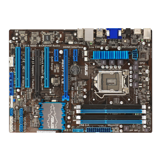
Page 20: Motherboard Layout
System panel connector (20-8 pin F_PANEL) Clear RTC RAM (3-pin CLRTC) USB 2.0 connectors (10-1 pin USB5~10) Serial port connectors (10-1 pin COM1) Front panel audio connector (10-1 pin AAFP) Digital audio connector (4-1 pin SPDIF_OUT) ASUS P8H77-V LE Page 1-30 1-29 1-31 1-23... -
Page 21: Central Processing Unit (Cpu)
Contact your retailer immediately if the PnP cap is missing, or if you see any damage to the PnP cap/socket contacts/motherboard components. ASUS will shoulder the cost of repair only if the damage is shipment/transit-related. • Keep the cap after installing the motherboard. ASUS will process Return Merchandise Authorization (RMA) requests only if the motherboard comes with the cap on the LGA1155 socket. -
Page 22: Installing The Cpu
1.6.1 Installing the CPU The LGA1156 CPU is incompatible with the LGA1155 socket. DO NOT install a LGA1156 CPU on the LGA1155 socket. 1-10 ASUS P8H77-V LE... - Page 23 Chapter 1: Product introduction 1-11...
-
Page 24: Cpu Heatsink And Fan Assembly Installation
1.6.2 CPU heatsink and fan assembly installation To install the CPU heatsink and fan assembly 1-12 Apply the Thermal Interface Material to the CPU heatsink and CPU before you install the heatsink and fan if necessary. ASUS P8H77-V LE... - Page 25 To uninstall the CPU heatsink and fan assembly Chapter 1: Product introduction 1-13...
-
Page 26: System Memory
The figure illustrates the location of the DDR3 DIMM sockets: P8H77-V LE P8H77-V LE 240-pin DDR3 DIMM sockets Recommended memory configurations One DIMM: We recommend you install one memory module in either of the blue slots (DIMM_A2 or DIMM_B2) to get better performance. -
Page 27: Memory Configurations
• The maximum 32GB memory capacity can be supported with 8GB or above DIMMs. ASUS will update the memory QVL once the DIMMs are available in the market. • The default memory operation frequency is dependent on its Serial Presence Detect (SPD), which is the standard way of accessing information from a memory module. - Page 28 P8H77-V LE Motherboard Qualified Vendors Lists (QVL) DDR3 1600 MHz capability Vendors Part No. A-DATA AM2U16BC2P1 A-DATA AX3U1600XB2G79-2X(XMP) A-DATA AM2U16BC4P2 A-DATA AX3U1600GC4G9-2G(XMP) A-DATA AX3U1600XC4G79-2X(XMP) CORSAIR TR3X3G1600C8D(XMP) CORSAIR CMD12GX3M6A1600C8(XMP) CORSAIR CMP4GX3M2A1600C8(XMP) CORSAIR CMP4GX3M2A1600C9(XMP) CORSAIR CMP4GX3M2C1600C7(XMP) CORSAIR CMX4GX3M2A1600C9(XMP) CORSAIR CMX4GX3M2A1600C9(XMP) CORSAIR TR3X6G1600C8 G(XMP)
- Page 29 P8H77-V LE Motherboard Qualified Vendors Lists (QVL) DDR3 1600 MHz capability (continued) Vendors Part No. KINGSTON KHX1600C9D3P1K2/8G Super Talent WA160UX6G9 Transcend JM1600KLN-8GK Asint SLZ3128M8-EGJ1D(XMP) Asint SLA302G08-EGG1C(XMP) Asint SLA302G08-EGJ1C(XMP) Elixir M2P2G64CB8HC9N-DG(XMP) 2GB Mushkin 998659(XMP) Mushkin 998659(XMP) PATRIOT PGS34G1600LLKA SanMax SMD-4G68HP-16KZ P8H77-V LE Motherboard Qualified Vendors Lists (QVL)
- Page 30 P8H77-V LE Motherboard Qualified Vendors Lists (QVL) DDR3 1333 MHz capability (continued) Vendors Part No. ELPIDA EBJ10UE8EDF0-DJ-F ELPIDA EBJ21UE8EDF0-DJ-F F3-10600CL8D-2GBHK G.SKILL (XMP) G.SKILL F3-10600CL9D-2GBNQ F3-10666CL7T-3GBPK G.SKILL (XMP) F3-10666CL8D- G.SKILL 4GBECO(XMP) F3-10666CL7T-6GBPK G.SKILL (XMP) F3-10666CL7D-8GBRH G.SKILL (XMP) GEIL GV32GB1333C9DC GEIL GG34GB1333C9DC...
- Page 31 P8H77-V LE Motherboard Qualified Vendors Lists (QVL) DDR3 1333 MHz capability (continued) Vendors Part No. Size KVR1333D3N9/4G-SP KINGSTON (low profile) Micron MT4JTF12864AZ-1G4D1 Micron MT8JTF12864AZ-1G4F1 Micron MT8JTF25664AZ-1G4D1 Micron MT8JTF25664AZ-1G4M1 Micron MT16JTF25664AZ-1G4F1 2GB Micron MT16JTF51264AZ-1G4D1 4GB NANYA NT4GC64B8HG0NF-CG AL7F8G73F-DJ2 AL8F8G73F-DJ2 SAMSUNG M378B2873FHS-CH9...
- Page 32 2 DIMMs: Supports two (2) modules inserted into either the blue slots or the • 4 DIMMs: Supports four (4) modules inserted into both the blue and black Visit the ASUS website at www.asus.com for the latest QVL. 1-20 Chip Size Chip NO.
-
Page 33: Installing A Dimm
1.7.3 Installing a DIMM Unplug the power supply before adding or removing DIMMs or other system components. Failure to do so can cause severe damage to both the motherboard and the components. Press the retaining clips outward to unlock a DIMM socket. Align a DIMM on the socket such that the notch on the DIMM matches the DIMM slot key on the socket. -
Page 34: Expansion Slots
This motherboard has two PCI Express 3.0/2.0 x16 slots that supports PCI Express 3.0/2.0 x16 graphic cards complying with the PCI Express specifications. 1.8.5 PCI slots The PCI slots support cards such as a LAN card, SCSI card, USB card, and other cards that comply with PCI specifications. 1-22 ASUS P8H77-V LE... -
Page 35: Clear Rtc Ram
CMOS RTC RAM data. The onboard button cell battery powers the RAM data in CMOS, which include system setup information such as system passwords. P8H77-V LE P8H77-V LE Clear RTC RAM To erase the RTC RAM: 1. Turn OFF the computer and unplug the power cord. -
Page 36: Connectors
Rear Speaker Out Line Out Front Speaker Out Mic In Mic In – – Speed Activity Link LAN port 6-channel 8-channel Rear Speaker Out Rear Speaker Out Front Speaker Out Front Speaker Out Bass/Center Bass/Center – Side Speaker Out ASUS P8H77-V LE... - Page 37 USB 2.0 ports 1 ~ 2. These four 4-pin Universal Serial Bus (USB) ports are available for connecting USB 2.0/1.1 devices. USB 3.0 ports 1 and 2. These two 9-pin Universal Serial Bus (USB) ports are available for connecting USB 3.0 devices. •...
-
Page 38: Front Panel Audio Connector
HD Audio or legacy AC`97 audio standard. Connect one end of the front panel audio I/O module cable to this connector. P8H77-V LE P8H77-V LE Front panel audio connector • We recommend that you connect a high-definition front panel audio module to this connector to avail of the motherboard’s high-definition audio capability. - Page 39 • If you are uncertain about the minimum power supply requirement for your system, refer to the Recommended Power Supply Wattage Calculator at http://support.asus. com/PowerSupplyCalculator/PSCalculator.aspx?SLanguage=en-us for details. Digital audio connector (4-1 pin SPDIF_OUT) This connector is for an additional Sony/Philips Digital Interface (S/PDIF) port.
- Page 40 The serial port bracket (COM1) is purchased separately. P8H77-V LE P8H77-V LE Serial port (COM1) connector USB 2.0 connectors (10-1 pin USB_5~10) These connectors are for USB 2.0 ports. Connect the USB module cable to any of these connectors, then install the module to a slot opening at the back of the system chassis.
- Page 41 This connector is for the additional USB 3.0 ports. Connect the USB 3.0 bracket cable to this connector, then install the USB 3.0 bracket to the rear side of the chassis. If your chassis support customized front panel installation, with ASUS USB 3.0 header, you can have a front panel USB 3.0 solution.
- Page 42 P8H77-V LE P8H77-V LE SATA 3.0Gb/s connectors • These connectors are set to [AHCI] by default. If you intend to create a Serial ATA RAID set using these connectors, set the SATA Mode Selection item in the BIOS to [RAID].
-
Page 43: System Panel Connector
System panel connector (20-8 pin PANEL) This connector supports several chassis-mounted functions. P8H77-V LE P8H77-V LE System panel connector • System power LED (2-pin PLED) This 2-pin connector is for the system power LED. Connect the chassis power LED cable to this connector. The system power LED lights up when you turn on the system power, and blinks when the system is in sleep mode. -
Page 44: Onboard Switches
If the installed DIMMs still fail to boot after the whole tuning process, the DRAM_LED lights continuously. Replace the DIMMs with ones recommended in the Memory QVL (Qualified Vendors Lists) in this user manual or on the ASUS website at www.asus.com. -
Page 45: Onboard Leds
The illustration below shows the location of the onboard LED. P8H77-V LE P8H77-V LE Onboard LED DRAM LED DRAM LED checks the DRAM in sequence during motherboard booting process. If an error is found , the LED next to the error device will continue lighting until the problem is solved. -
Page 46: Software Support
The contents of the Support DVD are subject to change at any time without notice. Visit the ASUS website at www.asus.com for updates. To run the Support DVD Place the Support DVD to the optical drive. -
Page 47: Chapter 2 Bios Information
BIOS in the future. Copy the original motherboard BIOS using the ASUS Update utility. 2.1.1 ASUS Update utility The ASUS Update is a utility that allows you to manage, save, and update the motherboard BIOS in Windows environment. ®... -
Page 48: Asus Ez Flash 2
Follow the onscreen instructions to complete the updating process. 2.1.2 ASUS EZ Flash 2 The ASUS EZ Flash 2 feature allows you to update the BIOS without using an OS-based utility. Before you start using this utility, download the latest BIOS file from the ASUS website at www.asus.com. -
Page 49: Asus Crashfree Bios 3 Utility
2.1.3 ASUS CrashFree BIOS 3 utility The ASUS CrashFree BIOS 3 is an auto recovery tool that allows you to restore the BIOS file when it fails or gets corrupted during the updating process. You can restore a corrupted BIOS file using the motherboard support DVD or a USB flash drive that contains the updated BIOS file. -
Page 50: Asus Bios Updater
2.1.4 ASUS BIOS Updater The ASUS BIOS Updater allows you to update BIOS in DOS environment. This utility also allows you to copy the current BIOS file that you can use as a backup when the BIOS fails or gets corrupted during the updating process. -
Page 51: Updating The Bios File
To update the BIOS file using BIOS Updater At the FreeDOS prompt, type bupdater /pc /g and press <Enter>. D:\>bupdater /pc /g The BIOS Updater screen appears as below. ASUSTek BIOS Updater for DOS V1.18 Current ROM BOARD: P8H77-V LE VER: 0236 DATE: 02/09/2012 PATH: P8H77VL.ROM... -
Page 52: Bios Setup Program
• The BIOS setup screens shown in this section are for reference purposes only, and may not exactly match what you see on your screen. • Visit the ASUS website at www.asus.com to download the latest BIOS file for this motherboard. - Page 53 Displays the CPU/motherboard temperature, CPU/5V/3.3V/12V voltage output, CPU/chassis fan speed UEFI BIOS Utility - EZ Mode P8H77-V LE BIOS Version : 0236 CPU Type : Intel(R) Core(TM) i5-2500 CPU 0 @ 3.30GHz Total Memory : 1024 MB (DDR3 1333MHz) Friday [10/08/2010]...
-
Page 54: Advanced Mode
The Advanced Mode provides advanced options for experienced end-users to configure the BIOS settings. The figure below shows an example of the Advanced Mode. Refer to the following sections for the detailed configurations. To access the EZ Mode, click Exit, then select ASUS EZ Mode. Back button Menu items... -
Page 55: Scroll Bar
Pop-up window Select a menu item and press <Enter> to display a pop-up window with the configuration options for that item. Scroll bar A scroll bar appears on the right side of a menu screen when there are items that do not fit on the screen. -
Page 56: Main Menu
Installed. After you set a password, these items show Installed. 2-10 Advanced Monitor 0236 x64 02/09/2012 8.0.0.1296 3300 MHz 1024 MB (DDR3) 1333 MHz English [Mon 09/27/2010] [16:46:15] Administrator [Español] [Русский] Exit Boot Tool Choose the system default language ASUS P8H77-V LE... -
Page 57: Administrator Password
Administrator Password If you have set an administrator password, we recommend that you enter the administrator password for accessing the system. Otherwise, you might be able to see or change only selected fields in the BIOS setup program. To set an administrator password: Select the Administrator Password item and press <Enter>. -
Page 58: Ai Tweaker Menu
F5: Optimized Defaults F10: Save ESC: Exit F12: Print Screen →←: Select Screen ↑↓: Select Item Enter: Select +/-: Change Opt. F1: General Help F2: Previous Values F5: Optimized Defaults F10: Save ESC: Exit F12: Print Screen ASUS P8H77-V LE... -
Page 59: Ai Overclock Tuner [Manual]
Target CPU Turbo-Mode Speed : xxxxMHz Displays the current CPU Turbo-Mode speed. Target DRAM Speed : xxxxMHz Displays the current DRAM speed. 2.4.1 Ai Overclock Tuner [Manual] Allows you to select the CPU overclocking options to achieve the desired CPU internal frequency. -
Page 60: Gpu Boost [Ok]
Use the <+> and <-> keys to adjust the value. Short Duration Power Limit [Auto] Allows you to limit the turbo ratio’s long duration power. Use the <+> and <-> keys to adjust the value. 2-14 SpeedStep Technology (EIST). ® ASUS P8H77-V LE... -
Page 61: Digi+ Vrm
Primary Plane Current Limit [Auto] Maximum instantaneous current allowed at any given time for CPU cores Use <+> and <-> key to adjust the value at 0.125A increment. . Secondary Plane Current Limit [Auto] Maximum instantaneous current allowed at any given time for Internal Graphics cores. Use <+>... -
Page 62: Cpu Voltage [Offset Mode]
Offset Mode Sign [+] This item appears only when you set the iGPU Voltage item to [Offset Mode]. To offset the voltage by a positive value. [–] To offset the voltage by a negative value. 2-16 ASUS P8H77-V LE... -
Page 63: Dram Voltage [Auto]
iGPU Offset Voltage [Auto] This item appears only when you set the iGPU Voltage item to [Offset Mode] and allows you to set the iGPU Offset voltage. The values range from 0.005V to 0.635V with a 0.005V interval. iGPU Manual Voltage [Auto] This item appears only when you set the iGPU Voltage item to [Manual Mode] and allows you to set a fixed iGPU voltage. -
Page 64: Advanced Menu
Version 2.10.1208. Copyright (C) 2012 American Megatrends, Inc. Exit Boot Tool Trusted Computing (TPM) settings →←: Select Screen ↑↓: Select Item Enter: Select +/-: Change Opt. F1: General Help F2: Previous Values F5: Optimized Defaults F10: Save ESC: Exit F12: Print Screen ASUS P8H77-V LE... -
Page 65: Cpu Power Management Configuration
Execute Disable Bit [Enabled] [Enabled] Enables the No-Execution Page Protection Technology. [Disabled] Forces the XD feature flag to always return to zero (0). Intel Virtualization Technology [Disabled] ® [Enabled] Allows a hardware platform to run multiple operating systems separately and simultaneously, enabling one system to virtually function as several systems. -
Page 66: Pch Configuration
S3 entry. Key in the desired value using the numeric keypad. 2.5.3 SATA Configuration While entering Setup, the BIOS automatically detects the presence of SATA devices. The SATA Port items show Not Present if no SATA device is installed to the corresponding SATA port. 2-20 ASUS P8H77-V LE... -
Page 67: System Agent Configuration
SATA Mode Selection [IDE] Allows you to set the SATA configuration. [IDE] Set to [IDE] when you want to use the Serial ATA hard disk drives as Parallel ATA physical storage devices. [AHCI] Set to [AHCI] when you want the SATA hard disk drives to use the AHCI (Advanced Host Controller Interface). -
Page 68: Usb Configuration
Sets the front panel audio connector (AAFP) mode to high definition audio. [AC97] Sets the front panel audio connector (AAFP) mode to legacy AC’97 Realtek LAN Controller [Enabled] [Enabled] Enables the Realtek LAN controller. [Disabled] Disables the controller. 2-22 ASUS P8H77-V LE... -
Page 69: Apm
Realtek PXE OPROM [Disabled] This item appears only when you set the previous item to [Enabled] and allows you to enable or disable the PXE OptionRom of the Realtek LAN controller. Configuration options: [Enabled] [Disabled] Serial Port Configuration The sub-items in this menu allow you to set the serial port configuration. Serial Port [Enabled] Allows you to enable or disable the serial port (COM).Configuration options: [Enabled] [Disabled]... -
Page 70: Monitor Menu
Version 2.10.1208. Copyright (C) 2012 American Megatrends, Inc. Exit Boot Tool →←: Select Screen ↑↓: Select Item Enter: Select +/-: Change Opt. F1: General Help F2: Previous Values F5: Optimized Defaults F10: Save ESC: Exit F12: Print Screen ASUS P8H77-V LE... -
Page 71: Chassis Fan Speed Low Limit [600 Rpm]
CPU Fan Profile [Standard] This item appears only when you enable the CPU Q-Fan Control feature and allows you to set the appropriate performance level of the CPU fan. [Standard] Sets to [Standard] to make the CPU fan automatically adjust depending on the CPU temperature. -
Page 72: Boot Menu
[Disabled] Disables the full screen logo display feature. Set this item to [Enabled] to use the ASUS MyLogo 2™ feature. Post Report [5 sec] This item appears only when the Full Screen Logo item is set to [Disabled] and allows you to set the waiting time for the system to display the post report. -
Page 73: Fast Boot [Enabled]
• To select the boot device during system startup, press <F8> when ASUS Logo appears. • To access Windows OS in Safe Mode, press <F8> after POST. -
Page 74: Tools Menu
> ASUS SPD Information 2.8.1 ASUS EZ Flash 2 Utility Allows you to run ASUS EZ Flash 2. Press [Enter] to launch the ASUS EZ Flash 2 screen. For more details, see section 2.1.2 ASUS EZ Flash 2. 2.8.2 ASUS O.C. Profile This item allows you to store or load multiple BIOS settings. -
Page 75: Exit Menu
Load Optimized Defaults Save Changes & Reset Discard Changes & Exit ASUS EZ Mode Launch EFI Shell from filesystem device Load Optimized Defaults This option allows you to load the default values for each of the parameters on the Setup menus. - Page 76 2-30 ASUS P8H77-V LE...
-
Page 77: Appendices
Cet appareil est conforme aux normes CNR exemptes de licence d’Industrie Canada. Le fonctionnement est soumis aux deux conditions suivantes : (1) cet appareil ne doit pas provoquer d’interférences et (2) cet appareil doit accepter toute interférence, y compris celles susceptibles de provoquer un fonctionnement non souhaité de l’appareil. ASUS P8H77-V LE... -
Page 78: Canadian Department Of Communications Statement
ASUS Recycling/Takeback Services ASUS recycling and takeback programs come from our commitment to the highest standards for protecting our environment. We believe in providing solutions for you to be able to responsibly recycle our products, batteries, other components as well as the packaging materials. Please go to http://csr.asus.com/english/Takeback.htm for the detailed recycling information in different... -
Page 79: Asus Contact Information
ASUS COMPUTER INTERNATIONAL (America) Address Telephone Web site Technical Support Telephone Support fax Online support ASUS COMPUTER GmbH (Germany and Austria) Address Web site Online contact Technical Support Telephone Support Fax Online support * EUR 0.14/minute from a German fixed landline; EUR 0.42/minute from a mobile phone.