Asus P8H61-M LX3 Manual
P8h61-m lx3 series
Hide thumbs
Also See for P8H61-M LX3:
- User manual (68 pages) ,
- Guía de inicio rápido (12 pages) ,
- Quick start manual (14 pages)
Table of Contents
Advertisement
Advertisement
Table of Contents

Related Manuals for Asus P8H61-M LX3


Summary of Contents for Asus P8H61-M LX3
- Page 1 P8H61-M LX3 Series • P8H61-M LX3 • P8H61-M LX3 PLUS...
- Page 2 Product warranty or service will not be extended if: (1) the product is repaired, modified or altered, unless such repair, modification of alteration is authorized in writing by ASUS; or (2) the serial number of the product is defaced or missing.
-
Page 3: Table Of Contents
Welcome! ..................1-1 Package contents ................. 1-1 Special features ................1-1 1.3.1 Product highlights ............1-1 1.3.2 Innovative ASUS features ..........1-3 Before you proceed ..............1-4 Motherboard overview ..............1-5 1.5.1 Placement direction ............1-5 1.5.2 Screw holes ..............1-5 1.5.3... - Page 4 Managing and updating your BIOS ..........2-1 2.1.1 ASUS Update utility ............2-1 2.1.2 ASUS EZ Flash 2 ............2-2 2.1.3 ASUS CrashFree BIOS 3 utility ........2-3 2.1.4 ASUS BIOS Updater ............2-4 BIOS setup program ..............2-7 Main menu .................. 2-11 2.3.1 System Language [English] ...........2-11...
- Page 5 Setup Mode [EZ Mode] ..........2-24 2.7.6 Boot Option Priorities ............ 2-24 2.7.7 Boot Override ..............2-24 Tools menu ................. 2-25 2.8.1 ASUS EZ Flash Utility ........... 2-25 2.8.2 ASUS SPD Information ..........2-25 2.8.3 ASUS O.C. Profile ............2-25 Exit menu ..................2-26 Appendices...
-
Page 6: Safety Information
Safety information Electrical safety • To prevent electric shock hazard, disconnect the power cable from the electric outlet before relocating the system. • When adding or removing devices to or from the system, ensure that the power cables for the devices are unplugged before the signal cables are connected. If possible, disconnect all power cables from the existing system before you add a device. -
Page 7: Conventions Used In This Guide
Refer to the following sources for additional information and for product and software updates. ASUS websites The ASUS website provides updated information on ASUS hardware and software products. Refer to the ASUS contact information. Optional documentation Your product package may include optional documentation, such as warranty flyers, that may have been added by your dealer. -
Page 8: P8H61-M Lx3 Series Specifications Summary
2 x DIMM, max. 16GB, DDR3 1333 / 1066 MHz, non-ECC, un-buffered memory Dual-channel memory architecture Refer to www.asus.com for the latest Memory QVL (Qualified Vendors List). ** When you install a total memory of 4GB capacity or more, Windows 32-bit operating system may only recognize less ®... - Page 9 1 x I/O shield 1 x User Manual 1 x Support DVD Support DVD Drivers ASUS utilities ASUS Update Anti-virus software (OEM version) Form factor MicroATX form factor: 8.9 in x 6.8 in (22.6 cm x 17.3 cm) * Specifications are subject to change without notice.
-
Page 11: Chapter 1: Product Introduction
® The motherboard delivers a host of new features and latest technologies, making it another standout in the long line of ASUS quality motherboards! Before you start installing the motherboard, and hardware devices on it, check the items in your package with the list below. - Page 12 ACPI management function to provide efficient power management for advanced operating systems. 100% All High-quality Conductive Polymer Capacitors (P8H61-M LX3 PLUS only) This motherboard uses all high-quality conductive polymer capacitors for durability, improved lifespan, and enhanced thermal capacity. ASUS P8H61-M LX3 Series...
-
Page 13: Innovative Asus Features
DIMMs, and helping with difficult POST situations. AI Suite II With its fast user-friendly interface, ASUS AI Suite II consolidates all the exclusive ASUS features into one simple to use software package. It allows you to supervise overclocking, energy management, fan speed control, and voltage and sensor readings. -
Page 14: Before You Proceed
BIOS file using the bundled support DVD or USB flash disk that contains the latest BIOS file. ASUS EZ Flash 2 ASUS EZ Flash 2 is a utility that allows you to update the BIOS without using an OS-based utility. ErP ready The motherboard is European Union´s Energy-related Products (ErP) -
Page 15: Motherboard Overview
Motherboard overview Before you install the motherboard, study the configuration of your chassis to ensure that the motherboard fits into it. Ensure that you unplug the power cord before installing or removing the motherboard. Failure to do so can cause you physical injury and damage motherboard components. 1.5.1 Placement direction When installing the motherboard, ensure that you place it into the chassis in the correct... -
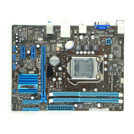
Page 16: Motherboard Layout
Clear RTC RAM (3-pin CLRTC) 1-17 ® DDR3 DIMM slots 1-12 USB connectors (10-1 pin USB56, USB78, 1-21 USB910) Intel H61 Serial ATA 3.0Gb/s connectors 1-20 Front panel audio connector (10-1 pin AAFP) 1-19 ® (7-pin SATA3G_1/2/3/4) ASUS P8H61-M LX3 Series... -
Page 17: Central Processing Unit (Cpu)
Contact your retailer immediately if the PnP cap is missing, or if you see any damage to the PnP cap/socket contacts/motherboard components. ASUS will shoulder the cost of repair only if the damage is shipment/transit-related. • Keep the cap after installing the motherboard. ASUS will process Return Merchandise Authorization (RMA) requests only if the motherboard comes with the cap on the LGA1155 socket. - Page 18 CPU notches. The CPU fits in only one correct orientation. DO NOT force the CPU into the socket to prevent bending Gold the connectors on the socket and triangle damaging the CPU! mark Alignment keys ASUS P8H61-M LX3 Series...
- Page 19 Apply some Thermal Interface Material to the exposed area of the CPU that the heatsink will be in contact with, ensuring that it is spread in an even thin layer. Some heatsinks come with pre- applied thermal paste. If so, skip this step.
-
Page 20: Installing The Cpu Heatsink And Fan
The type of CPU heatsink and fan assembly may differ, but the installation steps and functions should remain the same. The illustration above is for reference only. 1-10 ASUS P8H61-M LX3 Series... -
Page 21: Uninstalling The Cpu Heatsink And Fan
Connect the CPU fan cable to the connector on the motherboard labeled CPU_FAN. CPU_FAN P8H61-M LX3 Series P8H61-M LX3 Series CPU fan connector Do not forget to connect the CPU fan connector! Hardware monitoring errors can occur if you fail to plug this connector. 1.6.3 Uninstalling the CPU heatsink and fan To uninstall the CPU heatsink and fan:... -
Page 22: System Memory
DDR2 DIMM socket. DDR3 modules are developed for better performance with less power consumption. The figure illustrates the location of the DDR3 DIMM sockets: Channel Sockets Channel A DIMM_A1 Channel B DIMM_B1 P8H61-M LX3 Series P8H61-M LX3 Series 240-pin DDR3 DIMM sockets 1-12 ASUS P8H61-M LX3 Series... -
Page 23: Memory Configurations
1.7.2 Memory configurations You may install 1GB, 2GB, 4GB and 8GB unbuffered non-ECC DDR3 DIMMs into the DIMM sockets. • You may install varying memory sizes in Channel A and Channel B. The system maps the total size of the lower-sized channel for the dual-channel configuration. Any excess memory from the higher-sized channel is then mapped for single-channel operation. -
Page 24: Channel Memory Configuration
• A*: Supports one module inserted into either slot as single-channel memory configuration. • B*: Supports one pair of modules inserted into both the blue slots as one pair of dual- channel memory configuration. Visit the ASUS website at www.asus.com for the latest QVL. 1-14 ASUS P8H61-M LX3 Series... -
Page 25: Installing A Dimm
1.7.3 Installing a DIMM Unplug the power supply before adding or removing DIMMs or other system components. Failure to do so can cause severe damage to both the motherboard and the components. Press the retaining clips outward to DIMM notch unlock a DIMM socket. -
Page 26: Expansion Slots
This motherboard supports PCI Express x1 network cards, SCSI cards, and other cards that comply with the PCI Express specifications. 1.8.4 PCI Express x16 slot This motherboard has a PCI Express 2.0 x16 slot that supports PCI Express x16 2.0 graphic cards complying with the PCI Express specifications. 1-16 ASUS P8H61-M LX3 Series... -
Page 27: Jumpers
IRQ assignments for this motherboard Intel PCH SATA controller #0 – – – – shared – – – Intel PCH SATA controller #1 – – – – shared – – – Realtek 8111F controller – shared – – – – –... -
Page 28: Connectors
Mic In Bass/Center Bass/Center Lime (Front panel) – – – Side Speaker Out To configure an 8-channel audio output: Use a chassis with HD audio module in the front panel to support 8-channel audio output. 1-18 ASUS P8H61-M LX3 Series... -
Page 29: Internal Connectors
USB 2.0 ports 1 and 2. These two 4-pin Universal Serial Bus (USB) ports are for USB 2.0/1.1 devices. USB 2.0 ports 3 and 4. These two 4-pin Universal Serial Bus (USB) ports are for USB 2.0/1.1 devices. D-Sub port. This 15-pin port connects to a VGA monitor or other VGA-compatible devices. - Page 30 The system may become unstable or may not boot up if the power is inadequate. • If you are uncertain about the minimum power supply requirement for your system, refer to the Recommended Power Supply Wattage Calculator at http://support.asus. com/PowerSupplyCalculator/PSCalculator.aspx?SLanguage=en-us for details. Intel H61 Serial ATA 3.0Gb/s connectors (7-pin SATA3G_1~4)
- Page 31 • The two fan connectors support fans of maximum 2A (24 W) fan power. • Only the 4-pin CPU fan and chassis fan support the ASUS Q-Fan 2 and Fan Xpert features. USB connectors (10-1 pin USB56, USB78, USB910) These connectors are for USB 2.0 ports.
-
Page 32: Speaker Connector
Speaker connector (4-pin SPEAKER) The 4-pin connector is for the chassis-mounted system warning speaker. The speaker allows you to hear system beeps and warnings. SPEAKER P8H61-M LX3 Series PIN 1 P8H61-M LX3 Series Speaker out connector 1-22 ASUS P8H61-M LX3 Series... -
Page 33: Software Support
The contents of the Support DVD are subject to change at any time without notice. Visit the ASUS website at www.asus.com for updates. To run the Support DVD Place the Support DVD into the optical drive. - Page 34 1-24 ASUS P8H61-M LX3 Series...
-
Page 35: Chapter 2: Bios Information
BIOS in the future. Copy the original motherboard BIOS using the ASUS Update utility. 2.1.1 ASUS Update utility The ASUS Update is a utility that allows you to manage, save, and update the motherboard BIOS in Windows environment. ®... -
Page 36: Asus Ez Flash 2
Follow the onscreen instructions to complete the updating process. 2.1.2 ASUS EZ Flash 2 The ASUS EZ Flash 2 feature allows you to update the BIOS without using an OS-based utility. Before you start using this utility, download the latest BIOS file from the ASUS website at www.asus.com. -
Page 37: Asus Crashfree Bios 3 Utility
2.1.3 ASUS CrashFree BIOS 3 utility The ASUS CrashFree BIOS 3 is an auto recovery tool that allows you to restore the BIOS file when it fails or gets corrupted during the updating process. You can restore a corrupted BIOS file using the motherboard support DVD or a USB flash drive that contains the updated BIOS file. -
Page 38: Asus Bios Updater
2.1.4 ASUS BIOS Updater The ASUS BIOS Updater allows you to update BIOS in DOS environment. This utility also allows you to copy the current BIOS file that you can use as a backup when the BIOS fails or gets corrupted during the updating process. - Page 39 Backing up the current BIOS To backup the current BIOS file using the BIOS Updater Ensure that the USB flash drive is not write-protected and has enough free space to save the file. At the FreeDOS prompt, type bupdater /o[filename] and press <Enter>. D:\>bupdater /oOLDBIOS1.rom Filename Extension The [filename] is any user-assigned filename with no more than eight alphanumeric...
-
Page 40: Updating The Bios File
Select the Load Optimized Defaults item under the Exit menu. Refer to section 2.9 Exit menu for details. • Ensure to connect all SATA hard disk drives after updating the BIOS file if you have disconnected them. ASUS P8H61-M LX3 Series... -
Page 41: Bios Setup Program
• The BIOS setup screens shown in this section are for reference purposes only, and may not exactly match what you see on your screen. • Visit the ASUS website at www.asus.com to download the latest BIOS file for this motherboard. -
Page 42: Bios Menu Screen
Selects the boot device priority • The boot device options vary depending on the devices you installed to the system. • The Boot Menu(F8) button is available only when the boot device is installed to the system. ASUS P8H61-M LX3 Series... -
Page 43: Advanced Mode
The Advanced Mode provides advanced options for experienced end-users to configure the BIOS settings. The figure below shows an example of the Advanced Mode. Refer to the following sections for the detailed configurations. To access the EZ Mode, click Exit, then select ASUS EZ Mode. Back button Menu items... -
Page 44: Menu Items
You cannot select an item that is not user-configurable. A configurable field is highlighted when selected. To change the value of a field, select it and press <Enter> to display a list of options. 2-10 ASUS P8H61-M LX3 Series... -
Page 45: Main Menu
Main menu The Main menu screen appears when you enter the Advanced Mode of the BIOS Setup program. The Main menu provides you an overview of the basic system information, and allows you to set the system date, time, language, and security settings. EFI BIOS Utility - Advanced Mode Exit Main... -
Page 46: Administrator Password
To clear the user password, follow the same steps as in changing a user password, but press <Enter> when prompted to create/confirm the password. After you clear the password, the User Password item on top of the screen shows Not Installed. 2-12 ASUS P8H61-M LX3 Series... -
Page 47: Ai Tweaker Menu
Monitor Boot Tool Forces a DDR3 frequency slower than Target DRAM Speed : xxxxMHz the common tCK detected via SPD. According to Intel spec, ASUS H61 Series Memory Frequency Auto motherboard supports 1066/1333MHz DRAM (only). > DRAM Timing Control > CPU Power Management →←: Select Screen... -
Page 48: Dram Timing Control
Power Limit 1. Default setting is 1.25 times Power Limit 1. For Intel recommend, platform must be capable of supporting over Power Limit 2 for up to 10 msec. ASUS board can support over Power Limit 2 for a long duration. Use the <+> and <-> keys to adjust the value. -
Page 49: Advanced Menu
Primary Plane Current Limit [Auto] Maximum instantaneous current allowed at any given time for CPU cores. The value is represented in 1/8 A (0.125A) increment. Use the <+> and <-> keys to adjust the value. Secondary Plane Current Limit [Auto] Maximum instantaneous current allowed at any given time for internal graphics cores. -
Page 50: Cpu Configuration
Allows processor cores to run faster than marked frequency in specific condition. [Disabled] Disables this function. CPU C1E [Enabled] [Enabled] Enables the C1E support function. This item should be enabled in order to enable the Enhanced Halt State. [Disabled] Disables this function. 2-16 ASUS P8H61-M LX3 Series... -
Page 51: System Agent Configuration
CPU C3 Report [Enabled] Allows you to disable or enable the CPU C3 report to the operating system. Configuration options: [Disabled] [Enabled] CPU C6 Report [Enabled] Allows you to disable or enable the CPU C6 report to the operating system. Configuration options: [Enabled] [Disabled] 2.5.2 System Agent Configuration... -
Page 52: Usb Configuration
Disables the function. 2.5.6 Onboard Devices Configuration HD Audio Controller [Enabled] [Enabled] Enables the High Definition Audio Controller. [Disabled] Disables the controller. The following item appears only when you set the HD Audio Controller item to [Enabled]. 2-18 ASUS P8H61-M LX3 Series... -
Page 53: Apm
Front Panel Type [HD] Allows you to set the front panel audio connector (AAFP) mode to legacy AC’97 or high- definition audio depending on the audio standard that the front panel audio module supports. [HD] Sets the front panel audio connector (AAFP) mode to high definition audio. [AC97] Sets the front panel audio connector (AAFP) mode to legacy AC’97. -
Page 54: Monitor Menu
(RPM). If the fan is not connected to the motherboard, the field shows N/A. Select Ignore if you do not wish to display the detected speed. 2.6.3 CPU Q-Fan Control [Enabled] [Disabled] Disables the CPU Q-Fan control feature. [Enabled] Enables the CPU Q-Fan control feature. 2-20 ASUS P8H61-M LX3 Series... -
Page 55: Chassis Q-Fan Control [Enabled]
CPU Fan Speed Low Limit [600 RPM] This item appears only when you enable the CPU Q-Fan Control feature and allows you to disable or set the CPU fan warning speed. Configuration options: [Ignore] [200 RPM] [300 RPM] [400 RPM] [500 RPM] [600 RPM] CPU Fan Profile [Standard] This item appears only when you enable the CPU Q-Fan Control feature and allows you to set the appropriate performance level of the CPU fan. -
Page 56: Cpu Voltage, 3.3V Voltage, 5V Voltage, 12V Voltage
The onboard hardware monitor automatically detects the voltage output through the onboard voltage regulators. Select Ignore if you do not want to detect this item. 2.6.6 Anti Surge Support [Enabled] This item allows you to enable or disable the Anti Surge function. Configuration options: [Disabled] [Enabled] 2-22 ASUS P8H61-M LX3 Series... -
Page 57: Boot Menu
[Disabled] Disables the full screen logo display feature. Set this item to [Enabled] to use the ASUS MyLogo 2™ feature. Post Report [5 sec] This item appears only when the Full Screen Logo item is set to [Disabled] and allows you to set the waiting time for the system to display the post report. -
Page 58: Option Rom Messages [Force Bios]
• To select the boot device during system startup, press <F8> when ASUS Logo appears. • To access Windows OS in Safe Mode, press <F8> after POST. -
Page 59: Tools Menu
> ASUS O.C. Profile 2.8.1 ASUS EZ Flash Utility Allows you to run ASUS EZ Flash 2. Press [Enter] to launch the ASUS EZ Flash 2 screen. For more details, see section 2.1.2 ASUS EZ Flash 2. 2.8.2 ASUS SPD Information... -
Page 60: Exit Menu
This option allows you to enter the EZ Mode screen. Launch EFI Shell from filesystem device This option allows you to attempt to launch the EFI Shell application (shellx64.efi) from one of the available devices that have a filesystem. 2-26 ASUS P8H61-M LX3 Series... - Page 61 Chapter 2: BIOS information 2-27...
-
Page 62: Appendices
Appendices Notices Federal Communications Commission Statement This device complies with Part 15 of the FCC Rules. Operation is subject to the following two conditions: • This device may not cause harmful interference. • This device must accept any interference received including interference that may cause undesired operation. -
Page 63: Canadian Department Of Communications Statement
ASUS Recycling/Takeback Services ASUS recycling and takeback programs come from our commitment to the highest standards for protecting our environment. We believe in providing solutions for you to be able to responsibly recycle our products, batteries, other components as well as the packaging materials. Please go to http://csr.asus.com/english/Takeback.htm for the detailed recycling information in different... -
Page 64: Asus Contact Information
+1-510-739-3777 +1-510-608-4555 Web site usa.asus.com Technical Support Telephone +1-812-282-2787 Support fax +1-812-284-0883 Online support support.asus.com ASUS COMPUTER GmbH (Germany and Austria) Address Harkort Str. 21-23, D-40880 Ratingen, Germany +49-2102-959911 Web site www.asus.de Online contact www.asus.de/sales Technical Support Telephone +49-1805-010923* Support Fax...