
Related Manuals for UNI-T UT-P40


Summary of Contents for UNI-T UT-P40
- Page 1 UT-P40 AC/DCcurrentprobe UT-P40 交流/直流 電流探測鉗 UT-P30 ■ UT-P40 ■ INSTRUCTION MANUAL 使 用 說 明 書...
- Page 2 一般安全概述: 請仔細閱讀以下的安全防範措施以避免損傷並防止 損壞這個產品或任何連接到它的產品。為了避免潛 在的危險,請依所指示的 方法使用這個產品。 只有合格的人員可以執行服務程序。 ◆避免火災或人身傷害。 ◆正確的連接及拔除。在把探測鉗連結到要測試的電 路前,請先把探測鉗輸出端連接到測量儀器上。先把 探測鉗輸入端和地線從電路上拔除,才可把探測鉗從 測量儀器上拔除。 *注意:請盡量避免測試裸露線,如需測裸露線的話 請勿與測試端相接觸。 觀察所有的終端測定。為了避免火災或人身傷害,請 觀察所有在產品上的數據及標記。在連接產品前請先 閱讀手冊有關於進一 步測定的資訊。 ◆正確的更換電池。只能使用正確的類型和指定的電 池進行更換。 ◆沒有蓋子時請勿操作。蓋子或面板被去除時請勿操 作這個產品。 ◆避免曝露的電路。通電時,不要觸摸曝露的連接及 零件。...
- Page 3 ◆如有故障的疑慮,請勿操作。如果你懷疑產品有損 壞,請合格的服務人員檢查。 ◆在作業過程中必須確保所有的設備接地良好。 ◆請勿在潮濕的情況下操作。 ◆請勿在易燃的環境下操作。 ◆保持產品表面乾淨、乾燥。 安全聲明及標誌: 本手冊裡的名稱。這些名稱在本手冊中可能會出現。 注意。警告聲明指出那些可能導致損傷或喪 失生命的情況或做法。 小心警告。小心警告指出那些可能導致這產 品或其他所有物損壞的情況或做法。 產品上的聲明。這些聲明可能會出現在產品上: 危險 表示立即讀取標記時所造成的傷害。 注意 表示損傷危險不是立即的。 小心 表示對物產的傷害包括產品。 產品上的標誌。這些標誌可能會出現在產品上: 警告符號 雙層絕緣符號 準備啟動: 電流探測鉗 (圖 1)使一種通用示波器顯示 AC 及...
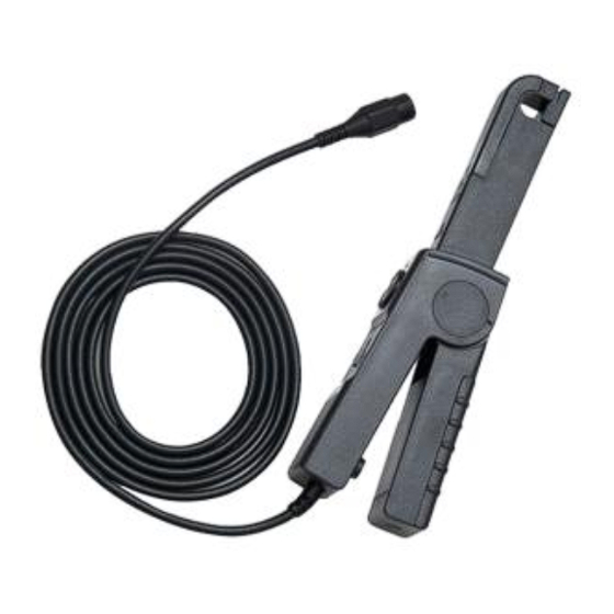
- Page 4 DC 電流訊號至 30Amps Peak (21A RMS)。該電 流 探測鉗也可以用多功能電表進行 AC 和 DC 的 數值 測 量(如下圖),選 購 本 公 司 附 件 MT-246N (BNC-to-banana)接頭轉接器即可用于測量。 Output Into Press Button Battery Cover Test Position Range Selection Max. 11¢Wire (Power On/Off)
- Page 5 探測鉗控制及指示 控制及指示 描述 電流流動記號。箭頭顯示探測器的極性來測量電流的流 動從正極到負極。 零位調整。當沒有通電時,轉動來調整探測棒輸出端至 零位。這也可以用在抵銷 DC 信號成分。測量 AC 數值時 不須做零位調整除非你的機器無法離析 DC 部分。 關 閉 / 範 圍 開 關 。 把 開 關 從 關 閉 滑 至 為 5mV/A 或 50mV/A 50mV/A 的範圍。無論選擇哪一個範圍,都會啟動探測 5mV/A 器,綠色燈將亮起。如果燈沒有亮,請參考電池注解及 安裝電池資料。 電池顯示燈。當探測棒是開啟時,綠色的電池顯示燈將 亮起。...
- Page 6 規格: UT-P40 適用於任何品牌示波器上使用。 示波器必須先預熱至少 20 分鐘並用在溫度(10-30) 與溼度(0-80)環境內。 表 1: 產品規格 尺寸 231 mm x67 mm x 36 mm 測量導體最大尺寸 10.3 mm 導線長度 200 cm 重量 310 g (不含電池重量) 表 2: 環境特性 工作時溫度 攝氏 0°C 到 + 50°C (華氏+32°F 到 + 122°F) 攝氏...
- Page 7 1. 把電流測試鉗的 BNC 頭連接到示波器的輸入端。 先設定示波器的頻道電壓輸入撥到到 DC 連結,電 壓靈敏刻度調到 5m V/div.。 2. 要 啟 動 電 流 測 試 鉗 , 把 開 關 移 至 5mV/A 或 50mV/A 的位置上。 (※UT-P40 電流探測鉗有綠色的 LED 電源/電池 顯示燈。如果 LED 燈沒有亮,請更換電池。) 3. 利用零位調整來設定零或補償探測鉗輸出端殘磁 直流電荷。 4. 要連接測試鉗到電路需打開夾片端並夾住導體。...
- Page 8 件 MT-246N (BNC-to-banana 轉接器) 連接至數 字電錶使用。MT-246N 有防呆裝飾,你只要把黑 色端接到電錶 COM(電錶印黑色), 然後紅色端接到V Ω輸入端(電錶印紅色)即可。 8. 如只要測量 AC 電流,把數字電錶調整至測量 AC 的位置。 9. 要測量 DC 電流,把數字電錶調整至測量 DC 的 位置。請注意測試鉗的電流箭頭以得到正確的極 性讀數。 10. 如要增加 UT-P40 電流探測鉗的測量敏感度, 把 測量的電線從夾片中穿過多繞幾圈,參考圖 2。 UT-P40 電流測試棒的敏感度是環繞夾片圈數的 好幾倍。 例如:50mV/A X5 圈=250mV/A *產品規格見 表 1 *環境特性見 表 2...
- Page 9 表 1-1: 電氣特性 電流範圍 5mV/A ; 50mV/A ±2% ±0.4A at 50mV/A (0.4A to 10 A p-p range) 典型 DC 精確度 ±2% ± 1A at 5mV/A (1A to 60 A p-p range) 最大工作電流 頻率範圍 DC to 100KHz (-3 dB) 典型的上升時間 3.5uS 噪音(Max) 2mV pk-pk 電池類型...
- Page 10 (範圍) 測定 5mV/A 50mV/A DC + peak AC peak AC peak-peak 1200 RMS CAT RMS CAT I 保養: CAT II 用這部分的資料來確保正確維護你的 UT-P40 AC/DC 電流探測鉗。 1. 關於乾電池的使用與注意事項: UT-P40 測試鉗用一顆長方形 9V 的電池。本機屬高 耗電產品,請指定使用鹼性電池。 當 UT-P40 的電池持續消耗著,可能會發生重大的增 益錯誤。綠色的 LED 燈將會持續的亮著直到電池降 到 6.5V。 如果測試棒有偵測到誤差,請立即更換新電池。...
- Page 11 當長時間(1 週以上)不使用本產品時,建議將乾電 池取出,因為乾電池會產生漏液,乾電池的電解液將 會銹蝕電路板,造成重大損壞,此外乾電池屬高污染 工業,因為乾電池的品質,我們無法掌控。 2.安裝電池 (1) 把測試鉗從電路上移開。 (2) 把側蓋板螺絲鬆開,就可看到乾電池,順便安裝 (或更換)乾電池。 (3) 觀察極性的同時,請把新的鹼性電池裝進指定的 鈕扣接頭,並且將乾電池放置在指定的位置。 把蓋子蓋上並輕輕的把螺絲鎖緊。 3. 清潔: 用微濕軟布沾點溫和的清潔液及水來清理電流探測 鉗的外表。要清理核心,把夾片打開並用沾了異丙 醇的棉布來清洗露出的表 面。用輕油來潤滑夾片的 齒合面。 不要用溶劑或研磨劑清洗。不要把電流探頭浸入液體 中。 4. 裝運的準備: 本公司有設計 UT-P40 專用的包裝箱,方便收納與裝 運,請勿任意丟棄。...
-
Page 12: General Safety Instructions
General Safety Instructions: Read the following safety instructions to avoid injury and prevent damage to this product or any products connected to it. Use this product only as specified. Only qualified personnel should perform service procedures. To Avoid Fire or Personal Injury Connect and Disconnect Properly. -
Page 13: Safety Terms And Symbols
Do not operate this product without the covers or panels. Avoid Exposed Circuitry. Do not touch exposed connections and components when power is present. Do Not Operate With Suspected Failures. If you suspect there is damage to this product, have it inspected by qualified service personnel. -
Page 14: Getting Started
DANGER Indicates an injury hazard immediately accessible as you read the marking. WARNING indicates injury hazard immediately accessible as you read the marking. CAUTION Indicates a hazard to property including the product. Symbols on the Product. These symbols may appear on the product: Attention refer to operation Instructions. - Page 15 PIC 1 Output Into Press Button Battery Cover Range Selection Test Position (Power On/Off) Max. 11¢Wire DC Zero Offset...
-
Page 16: Specifications
Shows the controls and indicators on the probe. current Control/Indicator Description Current flow symbol. The arrow shows the probe’s polarity convention for measuring current flowing from positive to negative. Zero adjustment. Rotate to adjust the probe output to zero when there is no current present. It may also be used to offset a DC signal component. -
Page 17: Environmental Characteristics
These characteristics apply to an adjusted UT-P40 AC/DC Current Probe installed on an oscilloscope of any brand. The oscilloscope must be warmed up for at least 20 minutes and be in an environment with the temperature at 10℃~30℃ and the humidity at 0~80. - Page 18 5m V/div. 2. Move the OFF/ Range switch to the 5 mV/A or 50 mV/A position to turn on the probe. (※The UT-P40 current probe has a green LED power/battery indicator. If the LED does not light, replace the battery or use specified power adaptor.)
- Page 19 Figure 3 shows the difference between the line current drawn by a resistive load and a motor controller. 7.Congratulations on your purchase of the UT-P40, a multifunctional current probe. When connecting to a digital meter,...
- Page 20 Note the current convention arrow on the probe to get the proper polarity reading. 10.To increase the measurement sensitivity of the UT-P40 current probe, loop additional turns of the wire under test through the jaws. See Figure 4. The sensitivity of the UT-P40 current probe is multiplied times the number of loops in the jaws.
-
Page 21: Electrical Characteristics
Electrical Characteristics Current Range 5mV/A ; 50mV/A ±2% ±0.4A at 50mV/A (0.4A to 10 A p-p range) DC Accuracy, typical ±2% ± 1A at 5mV/A (1A to 60 A p-p range) Maximum Working Current Frequency Range DC to 100KHz (-3 dB) Rise time,typical 2.5uS Noise(Max)