
Related Manuals for Energy zeroCO2 large RHI-3P5K-HVES-5G


Summary of Contents for Energy zeroCO2 large RHI-3P5K-HVES-5G
- Page 1 Three-phase Hybrid Inverter - 5G Operation Manual TM015 Rev.003 This manual refer to zeroCO2 large (5-10)K inverter models: RHI-3P5K-HVES-5G RHI-3P6K-HVES-5G RHI-3P8K-HVES-5G RHI-3P10K-HVES-5G...
-
Page 2: Table Of Contents
Table of Content Quick Guide ....................4 Wiring diagrams ................... 6 1. Introduction ....................8 Product Description ................8 Packing list ..................... 9 2. Safety & Warning ..................10 Safety ....................10 General Safety Instructions ..............10 Usage warnings ..................12 3. Overview .......................13 Screen ....................13 Keypad ....................13 Terminal Connection ................13... - Page 3 Battery Select ............... 42 5.6.4 Backup Control ..............43 5.6.4.1 Backup ON/OFF ..............43 5.6.4.2 Backup Settings ..............43 5.6.5 Storage Energy Set...............43 5.6.5.1 Meter Set ................43 5.6.5.2 STG Mode Select ..............45 5.6.6 STD Mode Settings ............... 47 5.6.7 Software Update ..............47 5.6.8...
-
Page 4: Quick Guide
Go to Main Menu. • Go to ADVANCED SETTINGS. • Type the password 0010 (DOWN -DOWN – UP – ENTER). • Go to STORAGE ENERGY SET. • Go to METER SET. • Select METER SELECT. • Select EASTRON 3PH METER (Choice valid for both models: SDM630 - SDM630MCT). - Page 5 Self Test CEI-0-21 • Go to Main Menu. • Go to ADVANCED SETTINGS. • Type the password 0010 (DOWN -DOWN – UP – ENTER). • Go to SELF TEST CEI 0 21. • Go to COMPLETE TEST. • Select YES and wait for the threshold analysis to complete. •...
-
Page 6: Wiring Diagrams
Wiring diagrams The following table shows the expected configurations. By clicking on the link in the DIAGRAM column you can download the corresponding wiring diagram. INVERTER METER EPS BOX SCHEMA Meter SDM630MCT WD047 LOAD BACKUP GRID Meter SDM630 WD046 LOAD BACKUP GRID LOAD BACKUP GRID LOAD BACKUP GRID No Meter... - Page 7 . 7 .
-
Page 8: Introduction
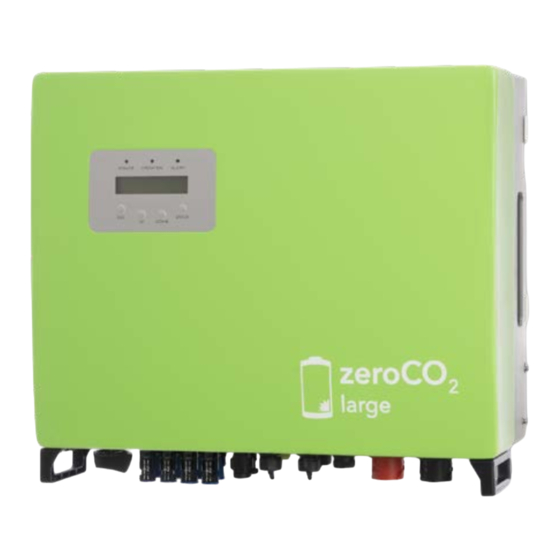
1. Introduction 1.1 Product Description zeroCO2 large (5-10)K Series is designed for residential hybrid systems, which can work with batteries to optimize self-consumption. LED Indicators Display Keypad DC Switch Figura 1 - Front side view Figura 2 - Bottom side view . -
Page 9: Packing List
1. Introduction 1.2 Packing list Please ensure that the following items are included in the packaging with your machine. Inverter mounting bracket Fixing screws AC—GRID Terminal AC—BACKUP Terminal DC (—) Connector Battery Connector DC ( ) Connector RJ45 Connector Use both connectors RS485 Meter Cable Eastron Meter for UK and AU... -
Page 10: Safety & Warning
2. Safety & Warning 2.1 Safety The following types of safety instructions and general information appear in this document as described below. DANGER “Danger”indicates a hazardous situation which if not avoided, will result in death or serious injury. WARNING “Warning” indicates a hazardous situation which if not avoided, could result in death or serious injury. - Page 11 CAUTION Risk of electric shock from energy stored in capacitors of the inverter, do not remove cover for 5 minutes after disconnecting all power sources (service technician only). Warranty may be voided if the cover is removed without authorization..
-
Page 12: Usage Warnings
2. Safety & Warning WARNING The zeroCO2 large (5-10)K series does not support parallel (three- and single-phase) operation on the AC-BACKUP port. Parallel operation of the unit will void the warranty. Figura 3 - Three-phase LOAD WARNING Please refer to the specification of the battery before configuration. 2.3 Usage warnings The inverter has been constructed according to the applicable safety and technical guidelines. -
Page 13: Overview
3. Overview 3.1 Screen zeroCO2 large (5-10)K series adopts LCD screen, it displays the status, operating information and settings of the inverter. 3.2 Keypad There are four keys in the front panel of the inverter (from left to right): ESC, UP, DOWN and ENTER keys. The keypad is used for: •... -
Page 14: Installation
4. Installation 4.1 Select a Location for the Inverter To select a location for the inverter, the following criteria should be considered: • Exposure to direct sunlight may cause output power derating. It is recommended to avoid installing the inverter in direct sunlight. •... - Page 15 4. Installation INVERTER INVERTER INVERTER 1000mm 1000mm 500mm 1000mm Figura 7 - Inverter Mounting clearance, side view INVERTER 500mm 500mm 500mm 1000mm Figura 8 - Minimum inverter mounting clearance, front view • Visibility of the LEDs and LCD should be considered. •...
-
Page 16: Equipment List To Be Used
4. Installation 4.2 Equipment list to be used PV Connector 3mm Allen key for AC Electrician screwdriver Level and meter crimping tool connectos fixing screws with insulated handles Grounding Measuring Dowel insertion hammer Torque wrench tool Digital multimeter and Pencil bricks wall 4 dowel and 4 screws... -
Page 17: Mounting The Inverter
4. Installation 4.3 Mounting the Inverter Figura 9 - Dimensions of mounting bracket Once a suitable location has be found (accordingly to “4.1 Select a Location for the Inverter” at page 14) using Figura 9 and Figura 10 mount the wall bracket to the wall. The inverter must be mounted vertically. -
Page 18: Pv Input Terminal Assembly
4. Installation • Lift up the inverter (be careful to avoid body strain) and align the back bracket on the inverter with the convex section of the mounting bracket. Hang the inverter on the mounting bracket and make sure the inverter is secure (see Figura 11). •... -
Page 19: Battery Terminal Components
4. Installation positiv terminal negativ terminal inverter terminal Figura 12 - Use appropriate crimping tools 4.5 Battery Terminal Components Quick connector is used for battery connection. The connector is suitable for tin-plated cables with a conductor cross section of 2,5 - 6 mm² (AWG14-10). Battery cable outside diameter range: 5,5 mm - 8,0 mm. - Page 20 4. Installation click! Figura 15 Collegamento positivo 2 Nm Figura 16 Collegamento positivo della batteria Battery positive socket Collegamento negativo Proprietà riservata. Riproduzione vietata ai temrini di legge-Copyright/ Reserved proprietorship. Forbidden reproduction to the terms of law-Copyright . M001-Rev.01 - 13/12/2016 Battery negative socket Collegamento negativo della batteria Figura 17...
-
Page 21: Assembling The Ac Connector
4. Installation NOTE Carefully read the battery’s user manual before connecting the battery. Perform the installation exactly as required by the battery manufacturer. WARNING Batteries power cables may be live. Remove the connectors with suitable dielectric gloves. 4.6 Assembling the AC Connector There are two AC terminals (AC backup and AC grid) and the assembly steps for both are the same. - Page 22 4. Installation CHIAVE PER SERRARE CHIAVE PER BLOCCARE FISSAGGIO AUSILIARIO 70mm 13mm Figura 19 - Stripped and bared wire Figura 20 - Internal structure of AC connector • Stripped the insulation sleeve of cable for 70 mm, up to discover the connector with copper core for 13mm (Figura 19).
-
Page 23: Meter Installation
4. Installation TIGHTENING TIGHTENING WRENCH WRENCH LOCKING LOCKING WRENCH WRENCH AUXILIARY FIXING 2.5÷4 Nm 2.5÷4 Nm Figura 22 - Assembly AC terminal • Connect AC connector with inverter, then tighten AC connector for clockwise (see Figura 22): a slight clicking sound indicates connection succeed Figura 22. clic Figura 23 - AC connector to inverter 4.7 Meter Installation... -
Page 24: Three-Phase Meter Installation (Installation With Ct)
4.7.1 Three-Phase Meter Installation (installation with CT) UTENZA 400V AC LOAD 400V AC CAVO DI COMUNICAZIONE RS485 RS485 COMMUNICATION CABLE IMPIANTO FOTOVOLTAICO SISTEMA DI ACCUMULO PHOTOVOLTAIC SYSTEM BATTERY ENERGY STORAGE SYSTEM CAN DMR WIFI TIPICO INVERTER ZERO CO2 TRIFASE BAT+ TYPICAL ZERO CO2 INVERTER... - Page 25 4. Installation CT DI MISURA MEASUREMENT SYSTEM RETE ENEL ENEL POWER SUPLIER CONTATORE BIDIREZIONALE DI SCAMBIO (ACQUISTO E VENDITA) BIDIRECTIONAL MEASUREM. METER SDM630MCT QUADRO DI PROTEZIONE SWITCH PROTECTION BOX CONTATORE DI PRODUZIONE PRODUCTION MEASUREMENT QUADRO DI PROTEZIONE SWITCH PROTECTION BOX AC GRID CKUP meter CT SDM630MCT 3pH (installation with CT) included in the kit...
-
Page 26: Three-Phase Meter Installation (Direct Insertion)
4.7.2 Three-Phase Meter Installation (direct insertion) UTENZA 400V AC LOAD 400V AC CAVO DI COMUNICAZIONE RS485 RS485 COMMUNICATION CABLE IMPIANTO FOTOVOLTAICO SISTEMA DI ACCUMULO PHOTOVOLTAIC SYSTEM BATTERY ENERGY STORAGE SYSTEM CAN DMR WIFI TIPICO INVERTER ZERO CO2 TRIFASE BAT+ TYPICAL ZERO CO2 INVERTER... - Page 27 4. Installation RETE ENEL ENEL POWER SUPLIER CONTATORE MEASUREMENT SYSTEM METER SDM630 QUADRO DI PROTEZIONE SWITCH PROTECTION BOX CONTATORE DI PRODUZIONE PRODUCTIONAL MEASUREMENT QUADRO DI PROTEZIONE SWITCH PROTECTION BOX AC GRID CKUP wer meter SDM630 3ph (direct insertion) not included in the kit CONN.
-
Page 28: Communication Cable Assembly
4. Installation 4.8 Communication Cable Assembly zeroCO2 large (5-10)K series inverter uses RS485 cable to communicate with the meter and CAN to communicate with the battery’s BMS. The image below shows the assembly of the RS485 / CAN communication cables. CONNESSIONE CAN 6÷8mm CONNESSIONE RS485... - Page 29 BLUE BIANCO VERDE WHITE GREEN ARANCIONE ORANGE 6÷8mm BIANCO ARANC. WHITE ORANGE 4. Installation INSERIMENTO CAVO CONNETTORIZZATO CAVO CAN COMPLETO INSERIMENTO CAVO CONNETTORIZZATO CAVO CAN COMPLETO ATTENTION: SERRARE CON LE MANI LA GHIERA KEEP ALIGNED ATTENZIONE: ALLINEARE I DUE RISCONTRI TIGHTEN WITH HANDS ATTENZIONE:...
-
Page 30: External Ground Connection
4. Installation 4.9 External ground connection An M4 screw is provided on the right side of the inverter for the earth connection. Connect a yellow/green cable with a section between 2.5 and 6mm². The section of the cable must be equivalent to or greater than that used for the AC connection (see 4.5). It is recommended to use an M4 size ring lug, crimped using suitable tools. -
Page 31: Inverter Monitoring Connection
4. Installation 4.12 Inverter monitoring connection The inverter can be monitored via Wi-Fi or LAN (optional). For connection instructions, please refer to “Quick Guide 4” at page 2. Mobile monitoring (APP:solis cloud) LAN monitoring (optional) Internet Router Web server Wi-Fi monitoring PC monitoring (www.soliscloud.com) Wi-Fi box... -
Page 32: Operation
Either the grid or solar cannot be detected. Pressing the ESC key Main menu calls back the previous menu Information UP/DOWN settings ENTER Monthly energy UP/DOWN Main interface advanced info Pressing the ENTER key to switch UP/DOWN to the submenu advanced settings Figura 37 - Operation Overview . -
Page 33: Main Menu
3. Advanced Info 4. Advanced Settings 5.3 Information In the “Information” section, operating data and information data can be viewed. Sub-sections include:: 1. General Info 2. System Info 3. Energy Records 4. BMS Info 5. Meter Info The example displays are shown in the following figures. DISPLAY DESCRIPTION Inverter SN: Shows the inverter serial number. - Page 34 000.0kWh GridGetE Total: Shows the total energy absorbed by the grid 000.0kWh GridGetE LastdayT: Shows the total energy absorbed by the grid up to yesterday (total 000.0kWh excluding today) GridGetE Today: Shows the total energy absorbed by the grid today 000.0kWh...
- Page 35 000.0kWh GridSendE Total: Shows the total energy fed into the grid 000.0kWh GridSendE LastdayT: Shows the total energy fed into the grid up to yesterday (total 000.0kWh excluded today) GridSendE Today: Shows the energy fed into the grid today 000.0kWh...
- Page 36 Shows phase C power on the meter. +000000W Meter Energy: Show energy records on the meter. 0000000.00kWh Output Energy: Show export energy records on the meter. 0000000.00kWh Input Energy: Show import energy records on the meter. 0000000.00kWh Meter Status: Shows meter’s communication status.
-
Page 37: Settings
5. Operation 5.4 Settings The following submenus are displayed when “Settings” menu is selected: 1. Set Time/Date 2. Set Address 5.4.1 Set Time/Date This function allows time and date setting. When this function is selected, the LCD will display a screen as shown in Figura 43. -
Page 38: Advanced Information
5. Operation 5.5 Advanced Information NOTE To access to this area is for fully qualified and accredited technicians only. Enter menu “Advanced Info.” (Password “0010”). Select “Advanced Info” from the main menu. The screen will require the password as below: Input Password X X X X Figura 46 - Enter Password After enter the correct password, the main menu will display a screen and be able to access to the following information.: 1. -
Page 39: Running Status
Shows the power output percentage of the inverter. 000% Inverter Temp: Shows internal IGBT temperature of the inverter. +000.0degC Grid Standard Shows current effective grid standard. Flash State: Reserved for Energy S.p.A. Technicians 00000000 DC Bus Voltage: DC bus voltage 000.0V Power Factor: Power factor +0.00... -
Page 40: Communication Data
01-05: 00 00 00 00 00 06-10: 00 00 00 00 00 Figura 50 - Communication Data 5.5.5 Yield Profile The yield profile includes: Energy Battery, Energy Grid and Energy Backup. All the historical energy generation records can be easily viewed in this section. Energy Battery Energy Grid Figura 51 - Communication Data 5.5.6 Inspection The screens display the operating parameters which guarantee compliance of the inverter with the CEI 0-21 standard. -
Page 41: Advanced Settings
Select “Advanced Settings” from the main menu to access the following options: 1. Select Standard 2. Grid Switches 3. Battery Control 4. Backup Control 5. Storage Energy Set 6. STD. Mode Settings 7. Software Update 8. Export Power Set 9. Reset Password 10. -
Page 42: Grid Switches
5. Operation 5.6.2 Grid Switches This function is used to start or stop the generation of the inverter. — Grid ON Grid OFF Figura 55 - Set Grid ON/OFF Screens can be scrolled manually by pressing the UP/DOWN keys. Press the ENTER key to save the setting. Press the ESC key to return to the previous menu. -
Page 43: Backup Control
There are two settings available in this section: Meter Select and Storage Mode Select. — Meter Select Stg Mode Select Figura 62 - Storage Energy Set 5.6.5.1 Meter Set Two settings are available in this section: meter select and meter placement. - Page 44 5. Operation 5.6.5.1.1 Meter Select This setting is used to select the meter type based on the actual configuration. When using the meter (insertion with CT) supplied with the inverter, select “Eastrom 3ph Meter”. 5.6.5.1.2 Meter Placement In “Meter Placement” setting three operating modes can be selected: • GRID: Meter installed at the connection point of the grid. GRID RETE ENEL ENEL POWER SUPLIER...
-
Page 45: Stg Mode Select
5. Operation • GRID+PV Inverter: One meter is connected to the grid connection point, the other meter is connected to the AC output port of an additional PV inverter (Easton Meter supported). GRID + PV INVERTER INVERTER FV METER UTENZA 400V AC RETE ENEL LOAD 400V AC ENEL POWER SUPLIER... - Page 46 If “Time of Use” is “Run”, the logic will follow the charging/discharging settings and time settings as defined in “Time of Use”. For those undefined period of time, it will still follow the Feed in Priority logic. Time of Use for Feed for priority. Path: Advanced Settings-> (Storage Energy Set-> Storage Mode Select-> Feed in Priority Mode->ON-> Time of use for Feed for priority. Mode: Feed in Priority Figura 68 3.
-
Page 47: Std Mode Settings
OverDischg SOC for Off-Grid Setting Range: From Battery “Forcecharge SOC” to 100%. PV Power Using Priority: Load>Battery Load Support Priority: PV>Battery Battery Charging Power comes from PV. Off-Grid Mode. Path: Advanced Settings->Storage Energy Set->Storage Mode Select-> Off-Grid Mode->ON- >Off Grid Mode Mode: Off-grid Figura 70 5.6.6 STD Mode Settings... -
Page 48: Export Power Set
5. Operation 5.6.8 Export Power Set This function is used to set the export power control. 1. EPM ON/OFF 2. Backflow Power 3. Failsafe ON/OFF Settings 2 and 3 are only valid when Setting 1 is set to “ON”. 5.6.8.1 EPM ON/OFF Enable/ Disable the function. -
Page 49: Restart Hmi
Function is available only when the Italian standard CEI021 is selected. 5.6.12 Compensation Set This function is used to calibrate the energy and output voltage of the inverter. Two sections are included: Power Parameter and Voltage Parameter. — Power Parameter... -
Page 50: Special Settings
The setting also corresponds to the current state which can be used to control the ON/ OFF state of the AFCI function. 5.7.2 EPS Mode NOTE The data shown in the following screen must only be modified by Energy S.p.A. ualified technicians. When the network is available, only the Network Port is enabled and the load supported via the EPS box from the network. -
Page 51: Maintenance
6. Maintenance 6.1 Cleaning zeroCO2 large (5-10)K series inverter does not require any regular maintenance. However, cleaning the heatsink will help inverter dissipating heat and increase the lifetime of inverter. The dirt on the inverter can be cleaned with a soft brush. The LCD and the LED status indicators lights can be cleaned with cloth if they are too dirty to be read. -
Page 52: Troubleshooting
In case of a failure the LCD screen will display an alarm message. In this case, the inverter may stop feeding energy into the grid. The alarm descriptions and their corresponding alarm messages are listed in Tab. 1 at page 53 When faults occur, the “Fault”... - Page 53 7. Troubleshooting Alarm Message Failure description Solution ARC-FAULT ARC detected in DC circuit Check if there's arc in PV connection and restart inverter. AFCI Check AFCI module self check Restart inverter or contact installer. FAULT fault DCinj-FAULT High DC injection current Restart inverter or contact installer.
- Page 54 7. Troubleshooting Alarm Message Failure description Solution OV-DCA-I DC input overcurrent Restart inverter. Identify and remove the string to the fault MPPT. Change power board. Over grid voltage Resistant of AC cable is too high. G-V01/02/03/04 Change bigger size grid cable. Adjust the protection limit if it’s allowed by electrical company.
- Page 55 If the inverter displays any alarm message as listed in Table 8.1; please turn off the inverter and wait for 5 minutes before restarting it. If the failure persists, please contact Energy S.p.A. service center. Please keep ready with you the following information before contacting us.
-
Page 56: Specifications
8. Specifications 8.1 Technical data Model RHI-3P5K-HVES-5G RHI-3P6K-HVES-5G Input DC (PV side) Recommended max. PV power [W] 8000 9600 Max. input voltage [V] 1000 Rated voltage [V] Start-up voltage [V] MPPT voltage range [V] 200-850 Full load MPPT voltage range [V] 200-850 240-850 Max. - Page 57 Model RHI-3P5K-HVES-5G RHI-3P6K-HVES-5G Efficiency Max. efficiency of Solar Inverting [%] 98,4 EU efficiency of Solar Inverting [%] 97,7 MPPT efficiency [%] 99,9 Battery charge/discharge efficiency [%] 97,5 Protection Anti-islanding protection Ground fault monitoring Residual current monitoring unit Output overcurrent protection Output shortcircuit protection Output overvoltage protection DC switch Reverse polarity protection Overvoltage protection Battery reverse protection General Data Dimensions [WxHxD mm] 535 x 455 x 181...
- Page 58 8. Specifications Model RHI-3P8K-HVES-5G RHI-3P10K-HVES-5G Input DC (PV side) Recommended max. PV power [W] 12800 16000 Max. input voltage [V] 1000 Rated voltage [V] Start-up voltage [V] MPPT voltage range [V] 200-850 Full load MPPT voltage range [V] 210-850 200-850 Max. input current [A] 26/13 26/26 Max.
- Page 59 8. Specifications Model RHI-3P8K-HVES-5G RHI-3P10K-HVES-5G Efficiency Max. efficiency of Solar Inverting [%] 98,4 EU efficiency of Solar Inverting [%] 97,7 MPPT efficiency [%] 99,9 Battery charge/discharge efficiency [%] 97,5 Protection Anti-islanding protection Ground fault monitoring Residual current monitoring unit Output overcurrent protection Output shortcircuit protection Output overvoltage protection DC switch Reverse polarity protection Overvoltage protection Battery reverse protection General Data Dimensions [WxHxD mm] 535 x 455 x 181...
-
Page 60: Appendix
9. Appendix 9.1 EPS Box Installation UTENZA 400V AC LOAD 400V AC UTENZE NON PRIORITARIE NO CRITICAL LOAD EPS BOX GRID BACKUP LOAD UTENZE PRIORITARIE CRITICAL LOAD SISTEMA DI ACC BATTERY ENERG STORAGE SYSTE IMPIANTO FOTOVOLTAICO PHOTOVOLTAIC SYSTEM QUADRO PROTEZ. SWITCH PROT.BOX TIPICO INVERTER ZERO CO2 TRIFASE TYPICAL ZERO CO2 INVERTER 3Ph... - Page 61 9. Appendix RETE ENEL ENEL POWER SUPLIER CT DI MISURA MEASUR. SYSTEM CONTATORE BIDIREZ. DI SCAMBIO (ACQUISTO E VENDITA) METER BIDIRECTIONAL MEASUR. SDM630MCT QUADRO DI PROTEZIONE SWITCH PROTECTION BOX CUMULO CONTATORE DI PRODUZIONE PRODUCTION MEASUREMENT QUADRO DI PROTEZIONE SWITCH PROTECTION BOX CAN DMR WIFI AC-BACKUP...
-
Page 62: Grid Standard Selection Guide
When the grid is lost, the backup port should be used to support the loads. An interlocking function between the backup port and grid port is necessary. Therefore, a separate EPS box (optional) and firmware upgrade is needed to achieve this function. Please consult Energy S.p.A. technicians for details and refer to the EPS box installation manual. 9.2 Grid standard selection guide NOTE Please check if the grid code setting comply with local requirement. - Page 63 9. Appendix Code in LCD Country/Region Comments VDE4015 Germany For German Low Voltage Grid. EN50549 PO Poland For Polish Low Voltage Grid. EN50549 NL Netherlands For Dutch Low Voltage Grid. EN50438 L — General EN50438 Requirement. Possible to be used in Austria, Cyprus, Finland, Czech Republic, Slovenia, etc.
- Page 64 Imported by: Energy S.p.A. Piazza Manifattura 1 38068 Rovereto (TN) - Italy Tel: +39 049 2701296 email: service@energysynt.com web: www.energyspa.com Product by: Ginlong Technologies Co., Ltd No. 57 Jintong Road, Binhai Industrial Park Xiangshan, Ningbo, Zhejiang, 315712, P.R.China Tel: +86 (0)574 6578 1806 Fax: +86 (0)574 6578 1606 email: info@ginlong.com...