Table of Contents
Advertisement
Quick Links
Advertisement
Table of Contents

Related Manuals for Asus EeeBox PC EB1007P


Summary of Contents for Asus EeeBox PC EB1007P
- Page 1 EBox1007P User Manual...
- Page 2 ASUSTeK COMPUTER, INC. (“ASUS”). Products and corporate names mentioned in this manual may or may not be registered trademarks or copyrights of their respective companies, and are used for identification purposes only.
-
Page 3: Table Of Contents
Contents ... 3 Notices ... 4 Safety information ... 9 Global Environmental Regulation Compliance and Declaration ...11 ASUS Recycling/Takeback Services ...11 ENERGY STAR complied product ...12 Notes for this manual ...12 Welcome ...13 Package contents ...13 Knowing your PC ...14 Front view ...14... -
Page 4: Notices
Notices Federal Communications Commission Statement This device complies with Part 15 of the FCC Rules. Operation is subject to the following two conditions: • This device may not cause harmful interference, and • This device must accept any interference received including interference that may cause undesired operation. - Page 5 RF exposure warning This equipment must be installed and operated in accordance with provided instructions and the antenna(s) used for this transmitter must be installed to provide a separation distance of at least 20 cm from all persons and must not be co-located or operating in conjunction with any other antenna or transmitter.
- Page 6 CE Marking CE marking for devices without wireless LAN/Bluetooth The shipped version of this device complies with the requirements of the EEC directives 2004/108/EC “Electromagnetic compatibility” and 2006/95/EC “Low voltage directive” . CE marking for devices with wireless LAN/ Bluetooth This equipment complies with the requirements of Directive 1999/5/ EC of the European Parliament and Commission from 9 March, 1999 governing Radio and Telecommunications Equipment and mutual...
- Page 7 France Restricted Wireless Frequency Bands Some areas of France have a restricted frequency band. The worst case maximum authorized power indoors are: • 10mW for the entire 2.4 GHz band (2400 MHz–2483.5 MHz) • 100mW for frequencies between 2446.5 MHz and 2483.5 MHz Channels 10 through 13 inclusive operate in the band 2446.6 MHz to 2483.5 MHz.
- Page 8 • This device must accept any interference, including interference that may cause undesired operation of the device. REACH Complying with the REACH (Registration, Evaluation, Authorization, and Restriction of Chemicals) regulatory framework, we publish the chemical substances in our products at ASUS REACH website at http://csr.asus.com/english/REACH.htm. EB1007P...
-
Page 9: Safety Information
Safety information Your PC is designed and tested to meet the latest standards of safety for information technology equipment. However, to ensure your safety, it is important that you read the following safety instructions. Setting up your system • Read and follow all instructions in the documentation before you operate your system. - Page 10 • The system does not function properly even if you follow the operating instructions. • The system was dropped or the cabinet is damaged. • The system performance changes. Lithium-Ion Battery Warning CAUTION: Danger of explosion if battery is incorrectly replaced.
-
Page 11: Global Environmental Regulation Compliance And Declaration
ASUS follows the green design concept to design and manufacture our products, and makes sure that each stage of the product life cycle of ASUS product is in line with global environmental regulations. In addition, ASUS disclose the relevant information based on regulation requirements. -
Page 12: Energy Star Complied Product
Department of Energy helping us all save money and protect the environment through energy efficient products and practices. All ASUS products with the ENERGY STAR logo comply with the ENERGY STAR standard, and the power management feature is enabled by default. The monitor and computer are automatically set to sleep after 15 and 30 minutes of user inactivity. -
Page 13: Welcome
Warranty card If the device or its components fail or malfunction during normal and proper use within the warranty period, bring the warranty card to the ASUS Service Center for replacement of the defective components. VESA mount and Screw pack... -
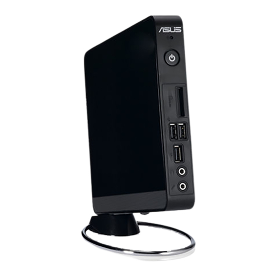
Page 14: Knowing Your Pc
Knowing your PC Front view Refer to the diagram below to identify the components on this side of the system. Hard disk LED The hard disk LED blinks when data is being written into or read from the hard disk drive. Power switch The power switch allows powering ON and OFF the system. - Page 15 Memory card slot The built-in memory card reader reads MMC/SD/SDHC cards used in devices like digital cameras, MP3 players, mobile phones, and PDAs. USB port The USB (Universal Serial Bus) port is compatible with USB devices such as keyboards, mouse devices, cameras, and hard disk drives.
-
Page 16: Rear View
Rear view Refer to the diagram below to identify the components on this side of the system. Antenna jack The jack is used to connect the supplied wireless antenna to enhance wireless signal reception. The antenna is installable/ removable according to need. Fasten the antenna onto the PC for better signal reception when Wi-Fi is in use. - Page 17 Power input (DC 19V) The supplied power adapter converts AC power to DC power for use with this jack. Power supplied through this jack supplies power to the PC. To prevent damage to the PC, always use the supplied power adapter. The power adapter may become warm to hot when in use.
-
Page 18: Top View
Top view Refer to the diagram below to identify the components on this side of the system. E-SATA E-SATA e-SATA Port External SATA or eSATA allows external connection of Serial-ATA devices originally designed for use inside the computer. It is up to six times faster than existing USB 2.0, & 1394 for external storage solutions and is also hot pluggable using shielded cables and connectors up to two meters. -
Page 19: Bottom View
Bottom view Refer to the diagram below to identify the components on this side of the system. Kensington® Lock Port The Kensington® lock port allows the PC to be secured using Kensington® compatible security products. These security products usually include a metal cable and lock that prevent the PC to be removed from a fixed object. -
Page 20: Positioning Your Pc
Positioning your PC Installing the stand (optional) Erect your PC with the optional stand. To do so: Locate the screw hole on the bottom of the PC. Align the stand screw to the PC screw hole, and then secure the stand to the PC with a coin. -
Page 21: Installing Your Pc To A Monitor (Optional)
Installing your PC to a monitor (optional) You can also install your PC to the back of a monitor. To do so: Secure the optional VESA mount to your monitor with four screws (HNM/M4 x 8). To fasten the VESA mount, your monitor must comply with VESA75 or VESA100 standard. -
Page 22: Setting Up Your Pc
Setting up your PC You need to connect peripherals before using your PC. Connecting to a display Connect one end of the VGA cable to an LCD monitor ( ) and the other end to the Display (Monitor) Output port on the system rear panel ( LCD monitor Connecting to USB devices... -
Page 23: Connecting To A Network Device
Connecting to a network device Connecting to LAN Connect one end of a network cable to the LAN port on the system rear panel and the other end to a hub or switch. Network cable with RJ-45 connectors Network hub or switch Connecting to Wi-Fi via wireless antenna The wireless antenna is provided for enhancing wireless signal reception. -
Page 24: Turning On The System
Turning on the system Connect the supplied AC adapter to the DC IN jack on the system rear panel, and then press the power switch on the front panel to turn on the system. • When your PC is not in use, unplug the power adapter or switch off the AC outlet to save on power consumption. -
Page 25: Using Your Pc
Using your PC All screenshots in this section are for reference only. Actual screen images may vary with operating systems.Visit the ASUS website at www.asus.com for the latest information. This PC is not supported under Windows Configuring wireless connection To connect to a wireless network, follow the instructions below: For security concerns, DO NOT connect to an unsecured network. -
Page 26: Configuring Wired Connection
Configuring wired connection To establish a wired network, follow the instructions below: Using a dynamic IP / PPPoE network connection: Click the network icon with a yellow warning triangle Windows® Notification area and select Open Network and Sharing Center. Click Change adapter settings in the left blue pane. - Page 27 Click Internet Protocol Version 4(TCP/IPv4) and click Properties. (Continue the following steps if using PPPoE) Return to the Network and Sharing Center and then click Set up a new connection or network. Click Obtain an IP address automatically and click EB1007P...
- Page 28 Select Connect to the Internet and click Next. Enter your User name and, Password, and Connection name. Click Connect. 11. Click the network icon in the taskbar and click the connection you just created. EB1007P Select Broadband (PPPoE) and click Next. 10.
- Page 29 Using a static IP: Repeat steps 1–4 in Using a dynamic IP to start the static IP network configuration. Click Use the following IP address. Enter the IP address, Subnet mask and Gateway from your service provider. If needed, enter the preferred DNS Server address and alternative address.
-
Page 30: Asus Easy Update
ASUS Easy Update ASUS Easy Update is a software tool that automatically detects and downloads the latest BIOS, drivers, and applications for your PC. From the Windows® notification area, right-click the ASUS Easy Update icon. Select Schedule to set how often you want to update your system. -
Page 31: Recovering Your System
Recovering your system Using the recovery partition The Recovery Partition includes an image of the operating system, drivers, and utilities installed on your system at the factory. The recovery partition provides a comprehensive recovery solution that quickly restores your system’s software to its original working state, provided that your hard disk drive is in good working order. - Page 32 Backing up the Factory Default Environment Data to a USB Drive (F9 Backup) Repeat steps 1–3 in the previous section. Select Backup the Factory Environment to a USB Drive and click Next. Connect a USB storage device to your PC to start the Factory Default Environment backup.
-
Page 33: Using The Usb Storage Device (Usb Restore)
Using the USB storage device (USB Restore) When the Recovery Partition in your system is crashed, use the USB storage device to restore the system to the factory default partition or the factory environment data to the entire hard disk. Connect the USB storage device that you back up the factory environment data to. - Page 34 Telephone Online support ASUS COMPUTER INTERNATIONAL (America) Address Telephone Web site Technical Support Telephone Support fax Online support ASUS COMPUTER GmbH (Germany and Austria) Address Web site Online contact Technical Support Component Telephone System/Notebook/Eee/ LCD Telephone Support Fax Online support...