Table of Contents
Advertisement
Quick Links
Installation Guide
Thank you for purchasing our product.
This document provides important information about safe and proper
operations of this Ethernet Switch.
Please read the "Important Safety Instructions" on pages from 3 to 5.
Any problems or damages resulting from disassembly of this Ethernet Switch
by customers are not covered by the warranty.
The instruction manuals (Menu Version, CLI Version,
Web Version), latest firmware and SDN application
(ZEQUO assist Plus) can be downloaded from the following URL.
https://panasonic.co.jp/ew/pewnw/english/datadownload/index.html
Panasonic Electric Works Networks Co.,Ltd.
2-12-7, Higashi-Shimbashi, Minato-ku, Tokyo Japan, 105-0021
©
Panasonic Electric Works Networks Co.,Ltd. 2022
Switch-M24eGi
Model No.
I0818- 5082 2
PN28240i-TH
PN28240i-MY
PN28240i-ID
PN28240i-SG
PN28240i-NZ
Printed in Japan
Advertisement
Table of Contents

Related Manuals for Panasonic PN28240i-NZ


Summary of Contents for Panasonic PN28240i-NZ
- Page 1 Web Version), latest firmware and SDN application (ZEQUO assist Plus) can be downloaded from the following URL. https://panasonic.co.jp/ew/pewnw/english/datadownload/index.html Panasonic Electric Works Networks Co.,Ltd. 2-12-7, Higashi-Shimbashi, Minato-ku, Tokyo Japan, 105-0021 © Panasonic Electric Works Networks Co.,Ltd. 2022 I0818- 5082 2 Printed in Japan...
-
Page 2: Table Of Contents
Contents Important Safety Instructions Basic Instructions for the Use of This Product 1 Product Outline 1.1 Features 1.2 Specifications 1.3 Accessories 1.4 Basic operation 2 Part Names and Functions 2.1 LED display change 3 Installation and Configuration 3.1 Grounding Cable Connection 3.2 Mounting on a wall 3.3 Mounting to rack 3.4 Configuration of IP address (Basic) -
Page 3: Important Safety Instructions
Important Safety Instructions This chapter contains important safety instructions for preventing bodily injury and/or property damage. Please read carefully, and follow them at all times. Severity of bodily injury and/or property damage, which could result from incorrect use of the Ethernet Switch, are explained below. WARNING This symbol indicates a potential hazard that could result in serious injury or death. - Page 4 WARNING Do not put the Ethernet Switch into fire. Deviation could lead to explosion and/or fire. If the device is going to be used in high temperature environments, do not perform the following operations with bare hands. - Relocating the installation area, transporting, and attaching, and removing attachment brackets, etc.
- Page 5 CAUTION Check whether the optical fiber cable connectors are contaminated with dust, etc. This might cause the optical signal to not be transmitted normally, and cause misoperations and malfunctions. If they are contaminated, make sure to clean them off, then connect them to the optical fiber ports. ...
-
Page 6: Basic Instructions For The Use Of This Product
When using two Ethernet Switches, do not stack them. When you place them side by side, allow for a space of 20 mm or more between them. 1. Please note that Panasonic shall not bear any liability whatsoever for any damages (this shall include, but is not limited to, lost earnings, lost opportunities, etc.) -
Page 7: Product Outline
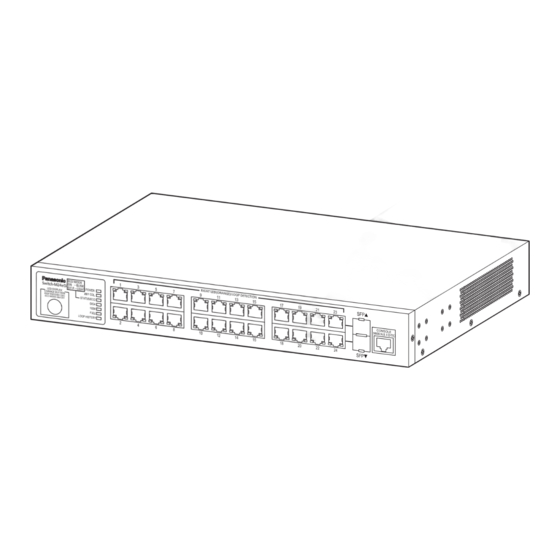
Product Outline Switch-M24eGi is an all Giga bit Ethernet Layer 2 Ethernet Switch with management function having 24 ports of 10/100/1000BASE-T and two pairs of 10/100/1000BASE-T port and SFP extension slot, one of which is selectable. 1.1 Features Has wire speed layer 2 switching functions. ... -
Page 8: Specifications
Communication control is available only for ports in the same group. (Up to 256 groups can be registered.) Management method ZEQUO assist Plus (Supplied from Panasonic’s website) SNMP v1/v2c/v3, Telnet, SSH (v2), WEB, CLI Loop detection Ports 1-22: ON, Ports 23, 24: OFF (default setting) -
Page 9: Accessories
Port LED does not light up. When the Eco mode is set,Port LED lamps do not light up. * For the configuration and management methods, please see the PDF version of the Operating Instructions on Panasonic’s website. -
Page 10: Part Names And Functions
Part Names and Functions Power cord hook block MAC address label Back panel LED display change button 10/100/1000BASE-T port Front panel Console port SFP extension slot Enlarged view on the next page Explanation label Power port Connect the supplied power cord to this port and connect the other end into an electric outlet. - Page 11 Power LED Collision LED Status/ECO mode LED LED display change GIGA mode LED button Speed modeLED DUPLEX mode LED Loop History mode LED POWER (Power) LED Green Light : Power is ON. : Power is OFF. ANY/COL. (Collision) LED Orange Light : During half-duplex operation, packet collision is occurring in either port.
- Page 12 Part Names and Functions Table1. Ports and Port LED lamps 1 to 24 correspond as shown below. Port LED Display mode Behavior Description STATUS/ECO Green Light Link is established. Green Blink Transmitting and receiving data. No device connected. Green Light Link is established at 1000 Mbps.
-
Page 13: Led Display Change
2.1 LED display change ●Display style set by the LED display change button Indication on the front panel and LED lamps LED display change button You can display the following items using the LED display switch button. Display for the connection with a connected terminal (Status mode),Display for the 1000 Mbps transmission rate (GIGA mode),Display for the 100Mbps or 10 Mbps transmission rate (Speed mode),Display for the full-duplex or half-duplex transmission system (DUPLEX mode),Display for ports with a loop history (Loop... - Page 14 Part Names and Functions Switch two types of Base modes and their LEDs in the following way: When Base mode is Status mode (factory default setting) Press "LED DISPLAY CHANGE BUTTON" manually. Automatic Boot Automatically returns to Base mode after 1 minute. Status mode DUPLEX Loop History...
-
Page 15: Installation And Configuration
Installation and Configuration 3.1 Grounding Cable Connection The chassis of the equipment must be grounded properly so that the lightning can flow to the ground, which improves the capability of the chassis for resisting the electromagnetic interference. 1. Ensure that the grounding cable is connected correctly so that the equipment is protected against lightning and interference. -
Page 16: Mounting On A Wall
Installation and Configuration 3.2 Mounting on a wall Use the two wall mount brackets and eight screws (for fixing the wall mount brackets to the Ethernet Switch) supplied with the mount brackets to fix the mount brackets to the four holes on each side of the Ethernet Switch. -
Page 17: Mounting To Rack
3.3 Mounting to rack Take out the provided mount brackets (2pcs.)and eight screws (for fixing the mount brackets and the Ethernet Switch).Fix the mount brackets to the four holes on each side of the Ethernet Switch using the screws. Then,securely install the Ethernet Switch on the rack using the four provided screws (for mounting on a 19-inch rack) or screws provided with the rack. -
Page 18: Configuration Of Ip Address (Basic)
Installation and Configuration 3.4 Configuration of IP address (Basic) (1) Connect this Ethernet Switch and PC with a RJ45–DSub 9-pin console cable and start up the terminal emulator (hyper terminal, etc.). (2) Pressing Enter key 3 times opens Login screen. Enter Login name and Password (the default is "manager"... - Page 19 Screen 3 Screen 4 Screen 5 For detailed settings and administration methods, please see the PDF version of the Operating Instructions on Panasonic’s website. - Detailed configuration and management methods using CLI/WEB. - Configuration and management method from ZEQUO assist Plus.
-
Page 20: Troubleshooting
Troubleshooting If you find any problem, please take the following steps to check. LED The POWER LED (Power) is not lit. Check if the power cord is disconnected. Please confirm that the power cord is securely connected to the power port. ...