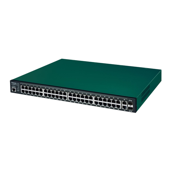
Panasonic GA-AS16TPoE+ Manual
Layer 2 switching hub
Hide thumbs
Also See for GA-AS16TPoE+:
- Installation manual (18 pages) ,
- Installation manual (17 pages)

Related Manuals for Panasonic GA-AS16TPoE+


Summary of Contents for Panasonic GA-AS16TPoE+
- Page 1 Layer 2 Switching Hub Model No. PN25161/PN25168 Reference PN25241/PN25248 PN25481/PN25488...
- Page 2 The target model for this document is as follows. Model name Model number Firmware version PN25168-TH PN25168-MY GA-AS16TPoE+ 1.0.0.07 and above PN25168-ID PN25168-SG PN25248-TH PN25248-MY GA-AS24TPoE+ PN25248-ID 1.0.0.07 and above PN25248-SG PN25248-NZ PN25488-TH PN25488-MY 1.0.0.10 and above GA-AS48TPoE+ PN25488-ID PN25488-SG PN25161-TH PN25161-MY GA-AS16T...
-
Page 3: Table Of Contents
Table of Contents Product Outline ..................5 1.1. Features ....................5 1.2. LED Behavior ..................6 1.2.1.LED Behavior during Start-up ............. 6 1.2.2.LED Behavior while Operating ............7 1.2.3.Operation Overview of PoE Power Supply Function ......9 Installation ....................10 Connection .................... - Page 4 5.2.10.PoE Port Config ................45 5.2.11.PoE Global Config ................. 47 5.2.12.Loop Detection Config ..............48 5.2.13.Loop History Info ................50 5.2.14.Port Group Config ................. 51 5.3. System Tools ..................52 5.3.1.Software Update ................52 5.3.2.Reboot .................... 53 5.3.3.Save Current Config ................ 54 5.3.4.Statistics ..................
-
Page 5: Product Outline
1. Product Outline GA-AS16TPoE+/AS24TPoE+/AS48TPoE+/AS16T/AS24T/AS48T are Ethernet Switching Hubs that feature the Web control function and 10/100/1000BASE-T ports. The downlink ports support the PoE power supply function for IEEE802.3at/af compatible devices. 1.1. Features ・ All ports (twisted pair ports) are 10/100/1000BASE-T ports that support auto- negotiation. -
Page 6: Led Behavior
1.2. LED Behavior 1.2.1. LED Behavior during Start-up When you turn on this switch, all LEDs are lit momentarily. Then, self-diagnosis of the hardware is conducted. When the self-diagnosis is com- pleted, the STATUS LED is lit in green, and the hardware starts operation as a switching hub. -
Page 7: Led Behavior While Operating
1.2.2. LED Behavior while Operating Each switch has system LEDs and a set of LEDs for each port. These LEDs indicate the operation status of the switch and each port. ・ System LEDs Figure 1-1 System LEDs LED names Behavior Description POWER LED Green light... - Page 8 ・ Port LEDs Port LED (Left) Port LED (Right) Figure 1-2 Port LEDs Port LEDs Behavior Description Left LINK/ACT Green Link established. light Green Transmitting data. blink No device connected. Right Green Supplying power normally. light Green The whole unit or the single port is overloaded. blink Not supplying power, or no PoE power receiving device connected.
-
Page 9: Operation Overview Of Poe Power Supply Function
1.2.3. Operation Overview of PoE Power Supply Func- tion The downlink ports can provide PoE power supply for IEEE802.3at/af compatible devices. A single port can supply power up to 30 W. The number of downlink ports and amount of power supply by the whole unit are shown below for each model. -
Page 10: Installation
2. Installation For the installation methods for each model, refer to the operating instructions. -
Page 11: Connection
3. Connection 3.1. Connecting a Twisted Pair Port ・ Connection Cable Use a CAT5E or higher straight cable (twisted pair cable) with 8P8C RJ45 modu- lar plugs. ・ Network Configuration Within 100 m Within 100 m Within 100 m Figure 3-1 Connection configuration example The length of the cable connecting this switch and a device must be 100 m or shorter. -
Page 12: Connecting To Power
3.2. Connecting to Power Connect the supplied power cord to the power port of this switch, and connect the power plug into an electric outlet. The switch operates at AC 100-240 V (50/60 Hz). It does not have a power switch. When you connect the power plug, the switch turns on and starts operating. -
Page 13: Web Browser-Based Control
4. Web Browser-based Control With the web browser-based control function (hereinafter referred to as the "Web control function"), you can configure the settings for this switch from a web browser's user interface via the network. The letters, numbers, and symbols that can be used for setting are as follows. ABCDEFGHIJKLMNOPQRSTUVWXYZ abcdefghijklmnopqrstuvwxyz 1234567890... -
Page 14: Ip Address Configuration
4.2. IP Address Configuration The IP address of this switch is not set as factory default. To access the Web con- trol function screen for this switch, you need to use the ZEQUO assist Plus applica- tion that can be downloaded from HP with the switch to set the IP address. For details, refer to the operation instructions for ZEQUO assist Plus. -
Page 15: Access To Web Control Function
4.3. Access to Web Control Function To use the Web control function, enter the IP address for this switch in the web browser's URL field ("location:", "address:", etc.) and press "Enter." Then, a login screen for this switch shown in Figure 4-1 is displayed. Enter the user name and password. - Page 16 When the above information has been authenticated properly, the screen shown in Figure 4-2 will appear for selecting a display language. Select the type of the language in which you want to show menus, and press "OK." Figure 4-2 Select Display Language The left side of the screen shows a list of actions that you can perform on this screen.
-
Page 17: Displaying Basic Information
4.4. Displaying Basic Information Select "General Info" to open the screen shown in Figure 4-3. This screen displays a list of this switch's basic information. Figure 4-3 General Info... - Page 18 Screen Description System Informa- Displays the operating time and firmware version of this switch. tion Operating Time Displays the cumulative time since the power on of this switch. Boot Code Ver- Displays the firmware version of this switch. * The firmware sion update described in Section 5.3.1 is available only for run- time codes.
-
Page 19: Switch Configuration
5. Switch Configuration After completing configuration, you must save the configuration information in accordance with Section 5.3.3. Unless you save the configuration information, the settings configured so far will not be reflected upon restart. 5.1. Basic Config 5.1.1. Administration Config Select "Basic Config"... -
Page 20: Ip Config
5.1.2. IP Config Select "Basic Config" and then "IP Config" to open the screen shown in Figure 5-2. On this screen, you can configure the IP address of this switch. Figure 5-2 IP Config Screen Description MAC Address Displays the MAC address of this switch. This value is uniquely assigned to each device and cannot be changed. -
Page 21: Basic Port Config
5.1.3. Basic Port Config Select "Basic Config" and "Port Config" and then "Basic Port Config" to open the screen shown in Figure 5-3. On this screen, you can display status and configure mode and other settings for each port. Figure 5-3 Basic Port Configuration... - Page 22 Screen Description Port Number Displays the port number. Type Displays the port type. 1000T The port type is 1000BASE-T. Link Status Displays the current link status. A link has been established successfully. Down A link has not been established. Port Status Displays the current port status.
-
Page 23: Extend Port Config
5.1.4. Extend Port Config Select "Basic Config" and "Port Config" and then "Extend Port Config" to open the screen shown in Figure 5-4. On this screen, you can display status and configure mode and other settings for each port. Figure 5-4 Extend Port Config Screen Description Global Jumbo Status Displays the jumbo frame settings. -
Page 24: Power Saving Config
5.1.5. Power Saving Config Select "Basic Config" and "Port Config" and then "Power Saving Config" to open the screen shown in Figure 5-5. On this screen, you can configure the power saving settings of each port. Figure 5-5 Power Saving Port Config Screen Description Port Number Displays the port number. -
Page 25: System Security
5.1.6. System Security Select "Basic Config" and "System Security" and then "System Security" to open the screen shown in Figure 5-6. On this screen, you can configure the various settings for accessing this switch for configuration and management. Figure 5-6 System Security Screen Description IP Setup Interface Displays the access settings for the IP address configuration software. -
Page 26: Syslog Transmission Config
5.1.7. Syslog Transmission Config Select "Basic Config" and "System Security" and then "Syslog Transmission Config" to open the screen shown in Figure 5-7. On this screen, you can configure the set- tings of the Syslog server information to which a system log is sent. Figure 5-7 Syslog Transmission Configuration Screen Description Global Syslog... -
Page 27: Id/Password Change
5.1.8. ID/Password Change Select "Basic Config" and "System Security" and then "ID/Password Change" to open the screen shown in Figure 5-8. On this screen, you can configure the user name/password. Figure 5-8 ID/Password Change Screen Description Current User ID Enter the current user name. This is used to login to this switch. -
Page 28: Fdb Table
5.1.9. FDB Table Select "Basic Config" and "FDB" and then "FDB Table" to open the screen shown in Figure 5-9. This screen shows the MAC addresses learned in the FDB table for each port. Figure 5-9 FDB Table Screen Description Aging Time Displays the time for which an automatically learned FDB entry is retained. -
Page 29: Time Config
5.1.10. Time Config Select "Basic Config" and then "Time Config" to open the screen shown in Figure 5- 10. On this screen, you can configure the SNTP synchronization settings. Figure 5-10 Time Configuration of This Switch Screen Description Time Zone Displays the time zone. -
Page 30: Static Arp Table
5.1.11. Static ARP Table Select "Basic Config" and "ARP Table" and then "Static ARP Table" to open the screen shown in Figure 5-11. On this screen, you can statically associate the IP address and MAC address and register that relationship to the ARP table. Figure 5-11 Static ARP Table Screen Description IP Address... -
Page 31: Arp Table
5.1.12. ARP Table Select "Basic Config" and "ARP Table" and then "ARP Table" to open the screen shown in Figure 5-12. This screen shows the ARP table. Figure 5-12 ARP Table Screen Description ARP Age Timeout Displays the time for which an automatically learned ARP table is retained. It is equal to the time after receiving the last packet. -
Page 32: Advanced Switch Configuration
5.2. Advanced Switch Configuration 5.2.1. VLAN Management Select "Advanced Config" and "VLAN" and then "VLAN Management" to open the screen shown in Figure 5-13. On this screen, you can configure the VLAN-related settings. Figure 5-13 VLAN Management Screen Description VLAN Status Displays the VLAN status. - Page 33 Management Indicates whether the VLAN is a management VLAN or not. VLAN Indicates that the VLAN is a management VLAN (VLAN that can communicate with the CPU). Down Indicates that the VLAN is not a management VLAN.
-
Page 34: Vlan Modification
5.2.1.a. VLAN Modification On the "VLAN Management" screen, select "Modify" to open the screen shown in Figure 5-14. On this screen, you can modify the VLAN configuration information. Figure 5-14 "VLAN Modification" Screen Screen Description VLAN ID Displays the VLAN ID. VLAN Name Displays the VLAN name. -
Page 35: Vlan Creation
5.2.2. VLAN Creation Select "Advanced Config" and "VLAN" and then "VLAN Creation" to open the screen shown in Figure 5-15. On this screen, you can create a new VLAN. Figure 5-15 "VLAN Creation" Screen Screen Description VLAN ID Set the VLAN ID. VLAN Name Set the VLAN name. -
Page 36: Vlan Port Config
5.2.3. VLAN Port Config Select "Advanced Config" and "VLAN" and then "VLAN Port Config" to open the screen shown in Figure 5-16. On this screen, you can configure the VLAN port set- tings. Figure 5-16 VLAN Port Config Screen Description Port Number Displays the port number. -
Page 37: Traffic Class Config
5.2.4. Traffic Class Config Select "Advanced Config" and "QoS Config" and then "Traffic Class Config" to open the screen shown in Figure 5-17. On this screen, you can configure the QoS and Traffic Class settings. Figure 5-17 QoS Config Screen Description Displays "Enable"/"Disable"... -
Page 38: Diffserv Config
5.2.5. Diffserv Config Select "Advanced Config" and "QoS Config" and then "Diffserv Config" to open the screen shown in Figure 5-18. On this screen, you can configure the Diffserv set- tings. Figure 5-18 Diffserv Settings Screen Description Diffserv Status Displays "Enable"/"Disable" of the Diffserv function. The factory default setting is "Disable". -
Page 39: Link Aggregation Config
5.2.6. Link Aggregation Config Select "Advanced Config" and then "Link Aggregation Config" to open the screen shown in Figure 5-19. On this screen, you can configure the group settings of link aggregation. Figure 5-19 Link Aggregation Config Screen Description Group Displays the group number of the link aggregation. -
Page 40: Link Aggregation Modification
5.2.6.a. Link Aggregation Modification Select "Advanced Config" and "Link Aggregation Config" and then click the "Mod- ify" button of each group to open the screen shown in Figure 5-20. On this screen, you can modify the link aggregation. Figure 5-20 Link Aggregation Modification Screen Description Displays the group number of the link aggregation. -
Page 41: Storm Control Config
5.2.7. Storm Control Config Select "Advanced Config" and then "Storm Control Config" to open the screen shown in Figure 5-21. On this screen, you can configure the storm control settings. Figure 5-21 Storm Control Configuration Screen Description Port Number Displays the port number. Unknown Unicast Enables or disables the Unknown unicast storm control. -
Page 42: Port Monitoring Config
5.2.8. Port Monitoring Config Select "Advanced Config" and then "Port Monitoring Config" to open the screen shown in Figure 5-22. On this screen, you can configure the port monitoring set- tings. Figure 5-22 Port Monitoring Configuration Screen Description Monitor Output Port Indicates a port number of a port used to monitor packets for another port. - Page 43 Note: Administrative packets such as Ping and ARP transmitted by this switch can- not be captured.
-
Page 44: Static Multicast Address Config
5.2.9. Static Multicast Address Config Select "Advanced Config" and then "Static Multicast Address Config" to open the screen shown in Figure 5-23. On this screen, you can manually register multicast addresses. Figure 5-23 Multicast Address Manual Register Screen Description VLAN ID Displays the VLAN ID of the multicast group if VLAN Status is enabled. -
Page 45: Poe Port Config
5.2.10. PoE Port Config Select "Advanced Config" and "PoE Config" and then "PoE Port Config" to open the screen shown in Figure 5-24. On this screen, you can configure the power supply settings by port. Figure 5-24 PoE Port Config... - Page 46 Screen Description Port Number Displays the port number. Admin. Displays whether or not the power can be supplied. Power supply is possible. Down Power supply is not possible. Status Displays the power supply status. Powered Indicates that power is supplied by PoE. Not Powered Indicates that power is not supplied by PoE.
-
Page 47: Poe Global Config
5.2.11. PoE Global Config Select "Advanced Config" and "PoE Config" and then "PoE Global Config" to open the screen shown in Figure 5-25. On this screen, you can configure the general PoE settings. Figure 5-25 PoE Global Configuration Screen Description Power Budget Displays the maximum amount of power this switch can supply. -
Page 48: Loop Detection Config
5.2.12. Loop Detection Config Select "Advanced Config" and "Loop Detection" and then "Loop Detection Config" to open the screen shown in Figure 5-26. On this screen, you can configure addi- tional settings. Figure 5-26 Loop Detection Config Screen Description Global Loop Detec- Displays the status of the Global Loop Detection function. - Page 49 Loop Detect Displays the setting status of the Loop detection and blocking function for that port. Enable The Loop detection and blocking function is enabled. (the factory default setting for a down-link port) Disable The Loop detection and blocking function is disabled. (the factory default setting for an up-link port) Mode Displays the setting status of the Loop detection mode for that port.
-
Page 50: Loop History Info
5.2.13. Loop History Info Select "Advanced Config" and "Loop Detection" and then "Loop History Info" to open the screen shown in Figure 5-27. On this screen, you can configure additional settings. Figure 5-27 Loop History Info Screen Description Number Displays the loop detection event number. Time Displays the time when the loop detection event occurred. -
Page 51: Port Group Config
5.2.14. Port Group Config Select "Advanced Config" and then "Port Group Config" to open the screen shown in Figure 5-28. On this screen, you can configure the port grouping settings. With port grouping, ports specified as members of the port group can communicate only with the member ports in the same group. -
Page 52: System Tools
5.3. System Tools 5.3.1. Software Update Select "System Tools" and then "Software Update" to open the screen shown in Fig- ure 5-29. On this screen, you can update the firmware. Figure 5-29 Software Update Screen Description Current Firmware Version Displays the current firmware version. TFTP Server IP Address Displays the IPv4 address of the TFTP server on which the firmware for update has been saved. -
Page 53: Reboot
5.3.2. Reboot Select "System Tools" and then "Reboot" to open the screen shown in Figure 5-30. On this screen, you can reboot this switch. Figure 5-30 Reboot Screen Description Reboot Option Displays the reboot method. The factory default setting is "Normal". Normal Normal reboot is executed. -
Page 54: Save Current Config
5.3.3. Save Current Config Select "System Tools" and then "Save Current Config" to open the screen shown in Figure 5-31. On this screen, you can save configuration information. Figure 5-31 Save Current Config Click "Save" to save this switch's settings to its internal RAM. Unless you save the configuration information, the settings configured so far will not be reflected upon restart. -
Page 55: Statistics
5.3.4. Statistics Select "System Tools" and then "Statistics" to open the screen shown in Figure 5-32. On this screen, you can check the statistics. Figure 5-32 Statistics Screen Description Target Port Displays the port number. Number Time Displays the time elapsed since power on or counter reset. Counter Name Displays the counter name. - Page 56 The counters are described below. Total RX Bytes Displays the number of bytes of all packets received. Total RX Pkts Displays the number of all packets received. Good Broadcast Displays the number of broadcast packets received. Good Multicast Displays the number of multicast packets received. CRC/Align Errors Displays the number of error packets that have a normal packet length (64 to 1518 bytes), but have an error found by an error detection code (FCS).
- Page 57 Click each counter name to open the screen shown in Figure 5-33. The total and per-second average of the counter for each port is displayed on the screen. Figure 5-33 Statistic Information of each Counter by Port Screen Description Port Number Displays the port number.
-
Page 58: System Log
5.3.5. System Log Select "System Tools" and then "System Log" to open the screen shown in Figure 5- 34. This screen displays the logs of events that occurred on this switch. By viewing events, you can keep track of activities that occurred on this switch, which are use- ful for network management. - Page 59 Screen Description Delete Log Deletes all system logs. Number Indicates the event number. System Log Sets enable/disable of the system log for each operation. For configuration details, Config refer to Section 5.3.5.a. Get Techni- Download the technical information as text file. cal Informa- tion Time...
- Page 60 Event Displays the description of the event that occurred on this switch. Start monitoring func- Indicates that the port monitoring function was enabled. tion Stop monitoring func- Indicates that the port monitoring function was disabled. tion SNTP first update to Indicates that this switch accessed the SNTP server to yyyy/mm/dd hh:mm:ss retrieve time information.
- Page 61 System exception in Indicates that the exception was occurred at the specific thread: THREAD free- thread. Mem:FREE_MEM! Reboot: Exception Indicates that the switch rebooted by exception handler. Occurred. The loop detected on Indicates that a loop was detected in Port X. portX.
-
Page 62: System Log Config
5.3.5.a. System Log Config Select "System Tools" and "System Log" and then "System Log Config" in the "Sys- tem Log" screen to open the screen shown in Figure 5-35. On this screen, you can configure enable/disable of the system log for each event. Figure 5-35 System Log Settings Screen Description Link Up/Down... -
Page 63: Config File Transfer
5.3.6. Config File Transfer Select "System Tools" and then "Config File Transfer" to open the screen shown in Figure 5-36. On this screen, you can upload and download configuration files. Figure 5-36 Config File Transfer Screen Description TFTP Server IP Displays the IPv4 address of the TFTP server that saves and reads the configura- tion file. -
Page 64: Ping Execution
5.3.7. Ping Execution Select "System Tools" and then "Ping Execution" to open the screen shown in Fig- ure 5-37. On this screen, you can send a ping. Figure 5-37 Ping Execution Screen Description Target IP Address Displays the IPv4 address of the target of the ping. The factory default setting is blank. -
Page 65: Exception Handler
5.3.8. Exception Handler Select "System Tools" and then "Exception Handler" to open the screen shown in Figure 5-38. On this screen, you can configure the exception handler. Figure 5-38 Exception Handler Screen Description Exception Handler Displays the exception handling function status. Enabled Enables the exception handling function. -
Page 66: Watchdog Timer
5.3.9. Watchdog Timer Select "System Tools" and then "Watchdog Timer" to open the screen shown in Fig- ure 5-39. On this screen, you can configure the Watchdog Timer settings. Figure 5-39 Watchdog Timer Screen Description Watchdog Timer Displays the status of the Watchdog Timer function. Enabled Enables the Watchdog Timer. -
Page 67: Appendix
6. Appendix 6.1. Specifications ○ Interface - Twisted pair ports: (RJ45 connector) * Refer to the "Specifications for each model" Transmission system IEEE802.3 10BASE-T IEEE802.3u 100BASE-TX IEEE802.3ab 1000BASE-T ○ Switching system - Store-and-forward system - Forwarding rate 10BASE-T 14,880 pps 100BASE-TX 148,800 pps 1000BASE-T/X... - Page 68 ○ Power supply specifications - Power supply (rated) * Refer to the following "Specifications for each model" - Power consumption * Refer to the following "Specifications for each model" ○ Environment specifications - Operating temperature * Refer to the following "Specifications for each model"...
- Page 69 Product Name GA-AS24T GA-AS24TPoE+ Product Number PN25241 PN25248 Number of Ports PoE+/PoE Power Supply Ports PoE+/PoE Function Yes (Total 168 W) MAC Address Table 8K entries / unit Buffer Memory 512KB Link Aggregation Up to 8 ports, 8 groups AC100-240V AC100-240V Power Supply (rated) 50/60Hz 1.7A...
-
Page 70: Easy Ip Address Setup Function
6.2. Easy IP Address Setup Function The following are points to note when using the easy IP address setup function. [Known compatible software] "ZEQUO assist Plus" Ver.1.2.0.0 [User-settable items] ・ IP address, subnet mask, and default gateway [Restrictions] ・ The time for accepting setting changes is limited to 20 minutes after power-on to ensure security. -
Page 71: Network Configuration Example And Notes Using Loop Detection And Blocking Function
6.3. Network Configuration Example and Notes Using Loop Detection and Blocking Function Configuration example using the Loop detection and blocking function Using the Loop detection and blocking function allows to prevent a loop failure possibly occurring on a downstream Switching Hub that the user directly uses. If you connect a hub that does not support the Loop detection and blocking func- tion to a downstream Switching Hub, and a loop failure occurs in the Switching Hub, the downstream Switching Hub port that caused a loop is blocked to prevent... - Page 72 Notes when using the Loop detection and blocking function - Disable the function on the upstream Switching Hub If you configure a network only with switches having the Loop detection and blocking function, the upstream Switching Hub may detect a loop occurring on the downstream Switching Hub first depending on the condition.
- Page 73 © Panasonic Electric Works Networks Co., Ltd. 2017-2022 2-12-7, Higashi-Shimbashi, Minato-ku, Tokyo Japan, 105-0021 URL: https://panasonic.co.jp/ew/pewnw/english/index.html P0217-6052...