Table of Contents
Advertisement
Quick Links
DIRECT-VENT FIREPLACE
OWNER'S OPERATION AND INSTALLATION MANUAL
PROPANE/LP GAS MODEL BDV34PA
WARNING: If the information in this manual is
not followed exactly, a fire or explosion may
result causing property damage, personal in-
jury, or loss of life.
FOR YOUR SAFETY
Do not store or use gasoline or other flammable
vapors and liquids in the vicinity of this or any
other appliance.
FOR YOUR SAFETY
WHAT TO DO IF YOU SMELL GAS
• Do not try to light any appliance.
• Do not touch any electrical switch
• Do not use any phone in your building.
• Immediately call your gas supplier from a
neighbor's phone. Follow the gas supplier's
instructions.
• If you cannot reach your gas supplier, call
the fire department.
This appliance may be installed in an aftermarket* manufactured (mobile) home, where
not prohibited by state or local codes.
*Aftermarket: Completion of sale, not for purpose of resale, from the manufacuter.
NATURAL GAS MODEL BDV34NA
Save this manual for future reference.
®
WARNING: Improper installation,
adjustment, alteration, service, or
maintenance can cause injury or
property damage. Refer to this
manual for correct installation and
operational procedures. For assis-
tance or additional information con-
sult a qualified installer, service
agency, or the gas supplier.
— Installation and service must be
performed by a qualified installer,
service agency, or the gas supplier.
— This appliance is only for use
with the type of gas indicated on
the rating plate. This appliance is
not convertible for use with other
gases, unless a certified kit is
used.
Advertisement
Table of Contents

Related Manuals for Vanguard BDV34NA


Summary of Contents for Vanguard BDV34NA
- Page 1 ® DIRECT-VENT FIREPLACE OWNER’S OPERATION AND INSTALLATION MANUAL NATURAL GAS MODEL BDV34NA PROPANE/LP GAS MODEL BDV34PA WARNING: Improper installation, WARNING: If the information in this manual is not followed exactly, a fire or explosion may adjustment, alteration, service, or result causing property damage, personal in- maintenance can cause injury or jury, or loss of life.
-
Page 2: Safety Information
BDV34NA AND BDV34PA ® DIRECT-VENT FIREPLACE (NATURAL/PROPANE/LP) SAFETY 1. This appliance is only for use with the 10. Have venting system inspected annu- type of gas indicated on the rating plate. ally by a qualified service person. If INFORMATION This appliance is not convertible for use... -
Page 3: Product Identification
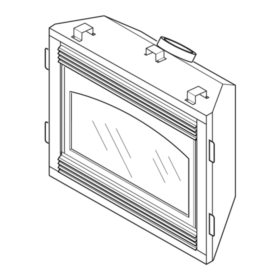
Valve Grate Assembly Glowing Embers Lava Rock Blower Adjustment (Optional Installation) Figure 1 - Vanguard Direct-Vent Fireplace BDV Series PRODUCT LOCAL CODES Install and use fireplace with care. Follow all FEATURES local codes. In the absence to local codes, use the current National Fuel Gas Code OPERATION ANS Z223.1, also known as NFPA 54* (USA) -
Page 4: Pre-Installation Preparation
Perpendicular walls 6" (152mm) Floor 0"/mm Determine the safest and most efficient loca- Ceiling to louver opening 42" (1067mm) tion for your Vanguard direct-vent fireplace. Front 36" (914mm) Make sure that rafters and wall studs are not Top of Standoffs 0"/mm in the way of the venting system. - Page 5 13" " 41" • Only use Vanguard or Simpson Dura- 29" Vent GS venting components or kits spe- cifically approved for this fireplace. • Minimum clearance between vent pipes and combustible materials is 1" (25 mm), except where stated otherwise.
-
Page 6: General Venting
BDV34NA AND BDV34PA ® DIRECT-VENT FIREPLACE (NATURAL/PROPANE/LP) GENERAL VENTING Continued Fixed Openable Fixed Closed Closed Openable TERMINATION CAP GAS METER RESTRICTED AREA AIR SUPPLY INLET (TERMINATION PROHIBITED) A = clearance above grade, veranda, porch, deck, or balcony I = clearance to service regulator vent outlet [*72 inches (1829mm) -
Page 7: Venting Installation
Do below. not use common vent systems. WARNING: Seal all vent con- Your Vanguard direct-vent fireplace has nections. Seal only the outer pipe been tested for a minimum 3' rise with a connections with high temperature WARNING: Horizontal sec- maximum 10"... -
Page 8: Installation
BDV34NA AND BDV34PA ® DIRECT-VENT FIREPLACE (NATURAL/PROPANE/LP) VENTING Snorkel INSTALLATION Continued INSTALLATION FOR HORIZONTAL TERMINATION 1. Determine the route your horizontal venting will take. Note: The location of the horizontal vent termination on the exterior wall must meet all local and 12"... - Page 9 OWNER’S MANUAL VENTING 4. Apply a bead of non-hardening mastic Carefully move the fireplace with vent around the outside edge of the vent cap. assembly attached toward the wall and INSTALLATION Position the vent cap in the center of insert the vent pipe into the horizontal the 7 "...
- Page 10 BDV34NA AND BDV34PA ® DIRECT-VENT FIREPLACE (NATURAL/PROPANE/LP) VENTING INSTALLATION Continued Horizontal Venting Vertical (V) Horizontal (H) Horizontal Termination 44" min. 29" max. Configurations (30° and 90° only, no vertical pipe) Figures 16 through 20 show different con- 55" min. 41" max.
- Page 11 OWNER’S MANUAL VENTING INSTALLATION Continued Venting with Two 90° Elbows Vertical (V) Horizontal (H Horizontal (H Horizontal (H 5' min. 2' max. 6' max. 6' min. 4' max. 12' max. 7' min. 6' max. 18' max. 8' min. 8' min. 20' max.
- Page 12 BDV34NA AND BDV34PA ® DIRECT-VENT FIREPLACE (NATURAL/PROPANE/LP) VENTING Flat Ceiling Installation Connect a section of pipe and extend up through the hole. 1. Cut a 10" square hole in the ceiling us- INSTALLATION Note: If an offset is needed to avoid ing the locating hole as a center point.
- Page 13 OWNER’S MANUAL VENTING Vertical Termination Configurations INSTALLATION Figures 25 through 28 show four different configurations for vertical termination. All connections must be sealed with high temperature silicone sealant as specified in the second Continued warning statement on page 7. 3. Lower the support box through the hole Venting with Two 90°...
- Page 14 BDV34NA AND BDV34PA ® DIRECT-VENT FIREPLACE (NATURAL/PROPANE/LP) VENTING INSTALLATION Continued Note: Install restrictor into 4" collar of stove as shown. RVF Kit Shown Vertical Venting Venting with Two 90° Elbows V = 40' max. Vertical (V Horizontal (H) Figure 28 - Vertical Rigid Venting 5' min.
-
Page 15: High Altitude Installation
INSTALLATION nized Pipe, 7" Adjustable Galva- (4) Spacer Springs, (2) 4" Hose nized Pipe (7-12"), Firestop Sup- Your Vanguard direct-vent fireplace has Clamps, (2) 7" Hose Clamps, RTV port, Roof Flashing, RTV Silicone, been AGA tested and approved for eleva-... -
Page 16: Fireplace Installation
BDV34NA AND BDV34PA ® DIRECT-VENT FIREPLACE (NATURAL/PROPANE/LP) CHECK GAS TYPE Installing GA3700/DA3610T FIREPLACE Blowers Use proper gas type for the fireplace unit INSTALLATION IMPORTANT : For clarity, gas valve assem- you are installing. If you have conflicting bly and grate/burner assembly are not shown gas types, do not install fireplace. - Page 17 OWNER’S MANUAL FIREPLACE Check to make sure that the power cord WARNING: Failure to position is completely clear of the blower wheel INSTALLATION the parts in accordance with sup- and that there are no other foreign ob- plied diagrams or failure to use jects in blower wheel.
- Page 18 BDV34NA AND BDV34PA ® DIRECT-VENT FIREPLACE (NATURAL/PROPANE/LP) FIREPLACE IMPORTANT: Install main gas valve CAUTION: Use only new, (manual shutoff valve) in an accessible lo- INSTALLATION black iron or steel pipe. Inter- cation. The main gas valve is for turning on nally-tinned copper tubing may or shutting off the gas to the appliance.
-
Page 19: Connecting Fireplace To Gas Supply
OWNER’S MANUAL FIREPLACE CHECKING GAS Pressurize supply piping system by ei- ther opening propane/LP supply tank CONNECTIONS INSTALLATION valve for propane/LP gas fireplace or opening main gas valve located on or near Continued WARNING: Test all gas pip- gas meter for natural gas fireplace, or ing and connections for leaks CONNECTING FIREPLACE using compressed air. - Page 20 BDV34NA AND BDV34PA ® DIRECT-VENT FIREPLACE (NATURAL/PROPANE/LP) FIREPLACE INSTALLING OPTIONAL Route the 25 ft. wire through openings provided on the sides of the fireplace WALL MOUNT SWITCH INSTALLATION to a convenient location to mount your GWMS2 switch. Continued 1. Connect one terminal of 25 ft. wire for...
- Page 21 OWNER’S MANUAL FIREPLACE Receiver Grasp door by both sides and ease it upward off of the lower bracket (see INSTALLATION Figure 45). Continued To replace glass door, follow the above instructions in reverse. INSTALLING OPTIONAL Terminal WIRELESS HAND-HELD Wires REMOTE CONTROL Battery Clip ACCESSORY - GHRC Top Louver...
- Page 22 BDV34NA AND BDV34PA ® DIRECT-VENT FIREPLACE (NATURAL/PROPANE/LP) FIREPLACE INSTALLATION Continued Left Side INSTALLING OPTIONAL Brick Panel BRICK LINER D8037A WARNING: If fireplace has been running, turn off and un- plug fireplace. Let cool before installing brick liner. This brick liner kit is optional. You may purchase brick liner from your local dealer or see Accessories, pages 32 and 33.
- Page 23 OWNER’S MANUAL FIREPLACE 6. Pull ember material apart into pieces no larger than a dime. Place these INSTALLATION pieces loosely and sparingly directly onto the exposed section of the front Continued burner and along the space between the INSTALLING LOGS, LAVA burner and grate prongs (see Figure 52).
-
Page 24: Operating Fireplace
BDV34NA AND BDV34PA ® DIRECT-VENT FIREPLACE (NATURAL/PROPANE/LP) OPERATING LIGHTING 11. Turn on all electric power to the fireplace. INSTRUCTIONS FIREPLACE 12. Turn gas control knob counterclock- wise to “ON”. 1. STOP! Read the safety information FOR YOUR SAFETY in column 1. -
Page 25: Optional Remote Operation
OWNER’S MANUAL OPERATING OPERATING INSPECTING OPTIONAL BLOWER FIREPLACE BURNERS ACCESSORY Continued Check pilot flame pattern and burner flame Locate the blower controls by opening patterns often. the lower louver panel on the fireplace. OPTIONAL REMOTE PILOT ASSEMBLY Blower controls are located on the left OPERATION side of the switch bracket to the left just The pilot assembly is factory preset for the... -
Page 26: Inspecting Burners
Figure 56 shows a typical flame pattern for compressed air to remove dust, dirt, or lint. form on the inside of the glass causing lint, models BDV34NA and BDV34PA. • Use a vacuum cleaner or small, soft bristled dust, and other airborne particles to cling to If burner flame pattern differs from that brush to remove excess dust, dirt, or lint. -
Page 27: Troubleshooting
OWNER’S MANUAL TROUBLESHOOTING WARNING: Turn off heater CAUTION: Never use a wire, and let cool before servicing. Only needle, or similar object to clean Note: For additional help, visit DESA a qualified service person should pilot. This can damage pilot unit. International’s technical service web service and repair heater. - Page 28 BDV34NA AND BDV34PA ® DIRECT-VENT FIREPLACE (NATURAL/PROPANE/LP) TROUBLESHOOTING Continued OBSERVED PROBLEM POSSIBLE CAUSE REMEDY Burner does not light after pilot is lit 1. Burner orifice clogged 1. Clean burner (see Cleaning and Maintenance, page 26) or replace burner orifice 2. Inlet gas pressure is too low 2.
- Page 29 OWNER’S MANUAL TROUBLESHOOTING Continued WARNING: If you smell gas • Shut off gas supply. • Do not try to light any appliance. • Do not touch any electrical switch; do not use any phone in your building. • Immediately call your gas supplier from a neighbor’s phone. Follow the gas supplier’s instructions.
-
Page 30: Replacement Parts
BDV34NA AND BDV34PA ® DIRECT-VENT FIREPLACE (NATURAL/PROPANE/LP) REPLACEMENT WIRING DIAGRAM PARTS CAUTION: Label all wires prior Note: Use only original replacement parts. to disconnection when servicing This will protect your warranty coverage for controls. Wiring errors can cause parts replaced under warranty. -
Page 31: Specifications
OWNER’S MANUAL SPECIFICATIONS BDV34NA BDV34PA 15,000/21,000 Btu/hr 16,000/20,000 Btu/hr Gas Type Natural Propane/LP Ignition Piezo Piezo Manifold Pressure 3.5" w.c. 10.0" w.c. Minimum Inlet Supply Pressure 4.5" w.c. 11.0" w.c. Dimension, Inches/mm (HxWxD) Fireplace (Actual size of firebox. Measurements do not 32 "... - Page 32 BDV34NA AND BDV34PA ® DIRECT-VENT FIREPLACE (NATURAL/PROPANE/LP) ACCESSORIES HEARTH BASE TRIM KIT (Not Shown) - For Use With QQQQQQ Purchase these fireplace accessories from QQQQQQ Hardwood Hearth Base your local dealer. If they can not supply QQQQQQ G3003J Series - Jade Marble these accessories, call DESA International’s...
- Page 33 OWNER’S MANUAL ACCESSORIES Continued DUPLEX OUTLET KIT GA3555 (Not Shown) For recessed installation when accessory blowers are used. MANUAL BLOWER KIT BRASS PERIMETER TRIM GA3700 RECEIVER AND HAND-HELD KIT - GA6090 (Not Shown) REMOTE CONTROL KIT Manual-variable control blower accessory for Optional three sided brass trim kit covers GHRC SERIES the BDV Series fireplaces.
- Page 34 BDV34NA AND BDV34PA ® DIRECT-VENT FIREPLACE (NATURAL/PROPANE/LP) ILLUSTRATED PARTS BREAKDOWN BDV34NA BDV34PA 11 (Included in Hardware Pack) 31-3 31-1 31-2 31-4 105980...
-
Page 35: Parts List
OWNER’S MANUAL PARTS LIST This list contains replaceable parts used in your fireplace. When ordering parts, follow the instructions listed under Replacement Parts on page 30 of this manual. DIRECT-VENT FIREPLACE BDV34NA BDV34PA PART NUMBER DESCRIPTION QTY. PART NUMBER DESCRIPTION QTY. -
Page 36: Warranty Information
WARRANTY INFORMATION KEEP THIS WARRANTY Model Serial No. Date Purchased Always specify model and serial numbers when communicating with the factory. We reserve the right to amend these specifications at any time without notice. The only warranty applicable is our standard written warranty.