Table of Contents
Advertisement
Quick Links
Advertisement
Table of Contents

Related Manuals for Supero SuperWorkstation 7045A-3


Summary of Contents for Supero SuperWorkstation 7045A-3
- Page 1 UPER ® 7045A-3 UPER ORKSTATION USER’S MANUAL...
- Page 2 Clara County in the State of California, USA. The State of California, County of Santa Clara shall be the exclusive venue for the resolution of any such disputes. Supermicro's total liability for all claims will not exceed the price paid for the hardware product.
-
Page 3: Preface
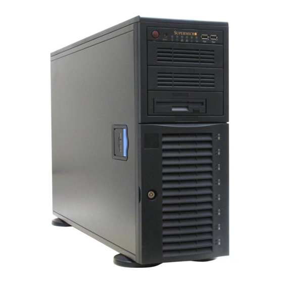
3. Installation and maintainance should be performed by experienced technicians only. The SuperWorkstation 7045A-3 is a high-end, dual processor workstation based on the SC743TQ-645 4U tower/rackmount chassis and the X7DA3, a dual processor serverboard that supports single or dual Intel at a Front Side (System) Bus speed of 1333/1066/667 MHz and up to 32 GB of ECC FBD DDR2-667/533 SDRAM. - Page 4 You should thoroughly familiarize yourself with this chapter for a general overview of safety precautions that should be followed when installing and servicing the SuperWorkstation 7045A-3. Chapter 5: Advanced Serverboard Setup Chapter 5 provides detailed information on the X7DA3 serverboard, including the locations and functions of connections, headers and jumpers.
- Page 5 Preface Notes...
-
Page 6: Table Of Contents
Manual Organization ... iii Chapter 1: Introduction Overview ... 1-1 Serverboard Features ... 1-2 Server Chassis Features ... 1-3 Contacting Supermicro ... 1-6 Chapter 2: Quick Setup Overview ... 2-1 Unpacking the System ... 2-1 Preparing for Setup ... 2-1 Installing the System into a Rack ... - Page 7 Chapter 5: Advanced Serverboard Setup Handling the Serverboard ... 5-1 Processor and Heatsink Installation ... 5-2 Connecting Cables ... 5-5 Connecting Data Cables ... 5-5 Connecting Power Cables ... 5-5 Connecting the Control Panel ... 5-6 I/O Ports ... 5-7 Installing Memory ...
- Page 8 UPER ORKSTATION 7045A-3 User's Manual AC'97 Audio ... 5-18 CD Connectors ... 5-18 Alarm Reset ... 5-18 Jumper Settings ... 5-19 Explanation of Jumpers ... 5-19 CMOS Clear ... 5-19 JLAN Enable/Disable ... 5-19 Watch Dog Enable/Disable ... 5-20 Audio Enable/Disable ... 5-20 Power Supply Fail Detect Enable/Disable ...
- Page 9 Chapter 7: BIOS Introduction ... 7-1 Running Setup ... 7-2 Main BIOS Setup ... 7-2 Advanced Setup ... 7-7 Security Settings ... 7-24 Boot Settings ... 7-25 Exit ... 7-26 Appendices Appendix A: BIOS POST Messages ... A-1 Appendix B: BIOS POST Codes ... B-1 Appendix C: SAS and Software Installation ...
- Page 10 UPER ORKSTATION 7045A-3 User's Manual Notes...
-
Page 11: Chapter 1: Introduction
Overview Supermicro's SuperWorkstation 7045A-3 is a high-end dual processor workstation that can be utilized either in a tower or in a rackmount confi guration. The 7045A-3 is comprised of two main subsystems: the SC743TQ-645 high-end server chassis and the X7DA3 dual Intel Xeon site for information on operating systems that have been certifi... -
Page 12: Serverboard Features
The X7DA3 supports single or dual LGA771 Intel Xeon 5100/5000 series proces- sors. Please refer to the serverboard description pages on our web site for a complete listing of supported processors (http://www.supermicro.com). Memory The X7DA3 has eight 240-pin DIMM slots that can support up to 32 GB of FBD (Fully Buffered DIMM) ECC DDR2-667/533 SDRAM. -
Page 13: Server Chassis Features
CPU overheat sensors, virus protection and BIOS rescue. Server Chassis Features The SuperWorkstation 7045A-3 is a scaleable server platform designed with today's most state-of-the-art features. The following is a general outline of the main features of the SC743TQ-645 server chassis. - Page 14 ORKSTATION 7045A-3 User's Manual Front Control Panel The control panel on the SuperWorkstation 7045A-3 provides you with system monitoring and control. LEDs indicate system power, HDD activity, network activity, overheat condition and power supply failure. A main power button and a system reset button are also included.
-
Page 15: System Block Diagram
Figure 1-1. Intel 5000X Chipset: System Block Diagram Note: This is a general block diagram. Please see Chapter 5 for details. PROCESSOR#2 667/1067/ 1333 MHz PCI-EXP X8 PCI-EXP X8 PCI-EXP X4 Port PCI-EXP X8 Port PXH-V #1,2 PCI-X 133 9410 PCI 32/ 33MMZ FRONT... -
Page 16: Contacting Supermicro
UPER ORKSTATION 7045A-3 User's Manual Contacting Supermicro Headquarters Address: SuperMicro Computer, Inc. 980 Rock Ave. San Jose, CA 95131 U.S.A. Tel: +1 (408) 503-8000 Fax: +1 (408) 503-8008 Email: marketing@supermicro.com (General Information) support@supermicro.com (Technical Support) Web Site: www.supermicro.com Europe Address: SuperMicro Computer B.V. -
Page 17: 2-1 Overview
If the server itself shows damage you should fi le a damage claim with the carrier who delivered it. Decide on a suitable location for the SuperWorkstation 7045A-3. It should be situated in a clean, dust-free area that is well ventilated. Avoid areas where heat, electrical noise and electromagnetic fi... -
Page 18: Choosing A Setup Location
UPER ORKSTATION 7045A-3 User's Manual Choosing a Setup Location - Leave enough clearance in front of the system to enable you to open the front door completely (~25 inches). - Leave approximately 30 inches of clearance in the back of the system to allow for suffi... -
Page 19: Rack Mounting Considerations
Chapter 2: Server Installation Rack Mounting Considerations Ambient Operating Temperature If installed in a closed or multi-unit rack assembly, the ambient operating tempera- ture of the rack environment may be greater than the ambient temperature of the room. Therefore, consideration should be given to installing the equipment in an environment compatible with the manufacturer’s maximum rated ambient tempera- ture (Tmra). -
Page 20: Installing The System Into A Rack
UPER ORKSTATION 7045A-3 User's Manual Installing the System into a Rack This section provides information on installing the system into a rack unit. Rack installation requires the use of the optional rackmount kit [CSE-PT26(B)]. If the system has already been mounted into a rack or if you are using it as a tower, you can skip ahead to Sections 2-5 and 2-6. -
Page 21: Installing The Chassis Rails
Chapter 2: Server Installation Installing the Chassis Rails You will need to remove the top bezel cover and the feet to add rack rails to the chassis. First, remove the top and right covers (top and left covers when standing as a tower chassis) by fi... -
Page 22: Installing The Rack Rails
Figure 2-3. Installing the Rails to the Chassis Installing the Rack Rails Determine where you want to place the SuperWorkstation 7045A-3 in the rack. (See Rack and Server Precautions in Section 2-3.) Position the fi xed rack rail/sliding rail guide assemblies at the desired location in the rack, keeping the sliding rail guide facing the inside of the rack. -
Page 23: Installing The Server Into The Rack
Chapter 2: Server Installation Installing the Server into the Rack You should now have rails attached to both the chassis and the rack unit. The next step is to install the server into the rack. You should have two brackets in the rack mount kit. -
Page 24: Checking The Serverboard Setup
UPER ORKSTATION 7045A-3 User's Manual Checking the Serverboard Setup After setting up the the system, you will need to open the unit to make sure the serverboard is properly installed and all the connections have been made. 1. Accessing the inside of the system (see Figure 2-5) (If rack mounted, fi... -
Page 25: Checking The Drive Bay Setup
Checking the Drive Bay Setup Next, you should check to make sure the peripheral drives and the SAS drives and SCA backplane have been properly installed and all connections have been made. 1. Accessing the drive bays All drives can be accessed from the front of the server. For servicing the DVD- ROM, IDE hard drives and fl... - Page 26 UPER ORKSTATION 7045A-3 User's Manual Figure 2-5. Accessing the Inside of the System (Rack Confi guration shown) 2-10...
-
Page 27: Chapter 3: System Interface
System Interface Overview There are several LEDs on the control panel as well as two for each SAS/SATA drive carrier and the Ethernet ports. These LEDs are to keep you constantly informed of the overall status of the system and the activity and health of specifi c components. There are also two buttons on the chassis control panel. -
Page 28: Control Panel Leds
UPER ORKSTATION 7045A-3 User's Manual Control Panel LEDs The control panel located on the front of the SC743TQ-645 chassis has six LEDs that provide you with critical information related to different parts of the system. This section explains what each LED indicates when illuminated and any corrective action you may need to take. -
Page 29: Power Fail
Power Fail: Indicates a power supply module has failed. This LED is inended for use with systems that have redundant power supply modules and therefore is not used with the SuperWorkstation 7045A-3. SAS Drive Carrier LEDs Each SAS drive carrier has two LEDs. - Page 30 UPER ORKSTATION 7045A-3 User's Manual Notes...
-
Page 31: Chapter 4: System Safety
Electrical Safety Precautions Basic electrical safety precautions should be followed to protect yourself from harm and the SuperWorkstation 7045A-3 from damage: Be aware of the locations of the power on/off switch on the chassis as well as the room's emergency power-off switch, disconnection switch or electrical outlet. -
Page 32: General Safety Precautions
General Safety Precautions Follow these rules to ensure general safety: Keep the area around the SuperWorkstation 7045A-3 clean and free of clut- ter. The SuperWorkstation 7045A-3 weighs approximately 63 lbs (28.6 kg). When lifting the system, two people at either end should lift slowly with their feet spread out to distribute the weight. -
Page 33: Esd Safety Precautions
After accessing the inside of the system, close the system back up and (if rackmounted) secure it to the rack unit with the retention screws after ensuring that all connections have been made. ESD Precautions Electrostatic discharge (ESD) is generated by two objects with different electrical charges coming into contact with each other. -
Page 34: Operating Precautions
UPER ORKSTATION 7045A-3 User's Manual Operating Precautions Care must be taken to assure that all chassis covers are in place when the Super- Workstation 7045A-3 is operating to ensure proper cooling. Out of warranty damage to the 7045A-3 system can occur if this practice is not strictly followed. Figure 4-1. -
Page 35: Chapter 5: Advanced Serverboard Setup
Advanced Serverboard Setup This chapter covers the steps required to install processors and heatsinks to the X7DA3 serverboard, connect the data and power cables and install add-on cards. All serverboard jumpers and connections are described and a layout and quick reference chart are included in this chapter. Remember to close the chas- sis completely when you have fi... -
Page 36: Processor And Heatsink Installation
UPER ORKSTATION 7045A-3 User's Manual Processor and Heatsink Installation When handling the processor, avoid placing direct pressure on the label area of the fan. Also, do not place the serverboard on a conductive surface, which can damage the BIOS battery and prevent the system from booting up. - Page 37 3. Use your thumb and your index fi nger to hold the CPU at opposite sides. 4. Align pin1 of the CPU (the cor- ner marked with a triangle) with the notched corner of the CPU socket. 5. Find the corner of the CPU that has a semi-circle cutout below a gold dot (CPU key).
- Page 38 UPER ORKSTATION 7045A-3 User's Manual Installing the Heatsink 1. Do not apply any thermal grease to the heatsink or the CPU die; the required amount has already been applied. 2. Place the heatsink on top of the CPU so that the four mounting holes are aligned with those on the (preinstalled) heatsink retention mechanism.
-
Page 39: Connecting Cables
Connecting Cables Now that the processors are installed, the next step is to connect the cables to the serverboard. These include the data (ribbon) cables for the peripherals and control panel and the power cables. Connecting Data Cables The ribbon cables used to transfer data from the peripheral devices have been carefully routed in preconfi... -
Page 40: Connecting The Control Panel
UPER ORKSTATION 7045A-3 User's Manual Connecting the Control Panel JF1 contains header pins for various front control panel connectors. See Figure 5-3 for the pin locations of the various front control panel buttons and LED indi- cators. Please note that even and odd numbered pins are on opposite sides of each header. -
Page 41: I/O Ports
Mouse/ keyboard USB0/1/2/3 Installing Memory Note: Check the Supermicro web site for recommended memory modules. Exercise extreme care when installing or removing DIMM modules to prevent any possible damage. Also note that the memory is inter- leaved to improve performance (see step 1). - Page 42 UPER ORKSTATION 7045A-3 User's Manual Memory Support The X7DA3 supports up to 32 GB of ECC FBD Fully Buffered DIMM) DDR2-667/533 in 8 sDIMM slots. Populating slots with a pair (or pairs) of DIMMs that are of the same size and same type in Bank1, Bank2, Bank3 and Bank4 will result in inter- leaving memory.
-
Page 43: Adding Pci Cards
Chapter 5: Advanced Serverboard Setup Adding PCI Cards 1. PCI slots The 7045A-3 can support six PCI expansion cards (one PCI-Express x16 slot, one PCI-Express x4 slot, two 64-bit 133/100 MHz PCI-X slots, one 64-bit 100 MHz slot and one 32-bit 33MHz PCI slot). 2. -
Page 44: Serverboard Details
UPER ORKSTATION 7045A-3 User's Manual Serverboard Details Figure 5-6. SUPER X7DA3 Layout Kybd/ FAN6 FAN5 JPW2 Mouse DIMM 4B USB0/1/2/3 DIMM 4A COM1 DIMM 3B DIMM 3A DIMM 2B Parallel Port DIMM 2A DIMM 1B DIMM 1A CD2 CD1 JLAN1/2 JPAC LP IPMI Speaker... - Page 45 X7DA3 Quick Reference Jumper Description 3rd Power Fail Detect JBT1 CMOS Clear JCF1 Compact Flash Master/Slave Select C1/2 C to PCI Slot #1 Enable/Disable C3/4 C to PCI Slot #6 Enable/Disable JPS1 SAS Controller Enable/Disable JPAC Audio Enable/Disable JPL1/ JPL2 JLAN1/JLAN2 Enable/Disable Watch Dog Connector...
-
Page 46: Connector Defi Nitions
UPER ORKSTATION 7045A-3 User's Manual Connector Defi nitions ATX Power Connector The power supply connector meets the SSI (Superset ATX) 24-pin specifi - cation. Make sure that the orientation of the connector is correct. See the table on the right for pin defi nitions. Secondary Power Connector In addition to the Primary ATX power... -
Page 47: Hdd Led
HDD LED The HDD (IDE Hard Disk Drive) LED connection is located on pins 13 and 14 of JF1. Attach the IDE hard drive LED cable to display disk activity. Refer to the table on the right for pin defi nitions. NIC1 LED The NIC1 (Network Interface Control- ler) LED connection is located on pins... -
Page 48: Reset Button
UPER ORKSTATION 7045A-3 User's Manual Reset Button The Reset Button connection is lo- cated on pins 3 and 4 of JF1. Attach it to the hardware reset switch on the computer case. Refer to the table on the right for pin defi nitions. Power Button The Power Button connection is located on pins 1 and 2 of JF1. -
Page 49: Serial Ports
Pin# Defi nition P/S 1 Fail Signal P/S 2 Fail Signal P/S 3 Fail Signal Reset Signal Note: This feature is only available when using redundant Supermicro power supplies. Fan Header Pin Defi nitions (Fan1-8) Pin# Defi nition Ground (Black) -
Page 50: Universal Serial Bus Headers
UPER ORKSTATION 7045A-3 User's Manual Universal Serial Bus Headers Two additional USB headers are located near the SATA5 header on the serverboard. This header is designated USB4/5 and is included for connection to the USB ports on the front of the chassis. A USB cable (not included) is needed for the con- nection. -
Page 51: Wake-On-Lan
Wake-On-LAN The Wake-On-LAN header is desig- nated JWOL. See the table on the right for pin defi nitions. You must enable the LAN Wake-Up setting in BIOS to use this feature. You must also have a LAN card with a Wake- on-LAN connector and cable. -
Page 52: Ac'97 Audio
Alarm Reset (JAR) The system will notify you in the event of a power supply failure. This feature assumes that Supermicro redundant power supply units are installed in the chassis. If you only have a single power supply installed, you should not connect anything to this jumper to prevent false alarms. -
Page 53: Jumper Settings
Jumper Settings Explanation of Jumpers To modify the operation of the serverboard, jumpers can be used to choose between optional settings. Jumpers create shorts between two pins to change the function of the connector. Pin 1 is identifi ed with a square solder pad on the printed circuit board. -
Page 54: Watch Dog Enable/Disable
UPER ORKSTATION 7045A-3 User's Manual Watch Dog Enable/Disable JWD controls the Watch Dog function. Watch Dog is a system monitor that can reboot the system when a software application hangs. Pins 1-2 will cause WD to reset the system if an application hangs. -
Page 55: Compact Flash Master/Slave
Compact Flash Master/Slave Select A Compact Flash Master (Primary)/Slave (Secondary) Select jumper is located at JCF1. Close this jumper to enable the use of a compact fl ash card. For the compact fl ash card and JCF1 to work properly, you will fi rst need to connect the compact fl... -
Page 56: 5-10 Onboard Indicators
UPER ORKSTATION 7045A-3 User's Manual 5-10 Onboard Indicators JLAN1/JLAN2 LEDs Each Ethernet port has two LEDs. One LED indicates activity while the other LED may be green, amber or off to indicate the speed of the con- nection. See the table on the right for the functions associated with the connection speed LED. -
Page 57: 5-11 Parallel Port, Floppy And Hard Drive Connections
5-11 Parallel Port, Floppy and Hard Drive Connections Note the following when connecting the fl oppy and hard disk drive cables: • The fl oppy disk drive cable has seven twisted wires. • A red mark on a wire typically designates the location of pin 1. •... -
Page 58: Floppy Connector
UPER ORKSTATION 7045A-3 User's Manual Floppy Connector The fl oppy connector is located near the IDE connectors. See the table below for pin defi nitions. SATA Ports There are no jumpers to con- fi gure the onboard SATA ports. See the table on the right for pin defi... -
Page 59: Ide Connectors
IDE Connectors There are two IDE connectors: IDE#1 (blue) and IDE#2 (white). IDE#1 is designated as the primary IDE drive. IDE#2 is designated as the secondary IDE drive and is reserved for Compact Flash card use only. See the table below for pin defi... -
Page 60: Sas Ports
UPER ORKSTATION 7045A-3 User's Manual SAS Ports There are eight SAS (Serial Attached SCSI) ports (one port for SAS0-3 and one port for SAS4-7) on the serverboard. See the table on the right for pin defi nitions. SAS Port Pin Defi nitions (SAS0-3 ~ SAS4-7) Pin# Defi... -
Page 61: Chapter 6: Advanced Chassis Setup
Advanced Chassis Setup This chapter covers the steps required to install components and perform simple maintenance on the SC743TQ-645 chassis. Following the component installation steps in the order given will eliminate most common problems. If some steps are unnecessary, skip ahead to the step that follows. Refer to Chapter 2 for instructions on installing the system as a 4U rackmount. - Page 62 UPER ORKSTATION 7045A-3 User's Manual Figure 6-1. Chassis Front View System LEDs USB Ports Main Power System Reset 5.25" Drive Bays (2) Floppy Drive Drive Bays (8)
-
Page 63: Front Control Panel
Front Control Panel The front control panel must be connected to the JF1 connector on the serverboard to provide you with system status and alarm indications. A ribbon cable has bundled these wires together to simplify this connection. Connect the cable from JF1 on the serverboard (making sure the red wire plugs into pin 1) to the appropriate comnnec- tor on the front control panel PCB (printed circuit board). -
Page 64: System Fans
3. Installing a new system fan Replace the failed fan with an identical one (available from Supermicro). Install and reassemble it in the fan housing then plug the housing back into its slot; it should click into place when fully inserted. Check that the fan is working properly and replace the top/left side chassis panel. - Page 65 Chapter 6: Advanced Chassis Setup Figure 6-3. Removing a Chassis Fan Figure 6-4. Removing the Air Shroud...
-
Page 66: Drive Bay Installation
UPER ORKSTATION 7045A-3 User's Manual Drive Bay Installation SAS/SATA Drives Eight SAS/SATA drives may be housed in the SC743TQ-645 chassis. The SAS/ SATA drive IDs are preconfi gured as 0 through 7 in order from right to left (or from bottom to top if rackmounted). - Page 67 Figure 6-5. Removing a SAS/SATA Drive Carrier Figure 6-6. Mounting a SAS/SATA Drive in a Carrier Important! Regardless of how many SAS/SATA hard drives are in- stalled, all drive carriers must remain in the drive bays to promote proper airfl ow. 3.
-
Page 68: Installing Components In The 5.25" Drive Bays
UPER ORKSTATION 7045A-3 User's Manual Installing Components in the 5.25" Drive Bays 1. Drive bay confi guration The 7045A-3 has two 5.25" drive bays. Components such as an extra fl oppy drive, IDE hard drives or CD-ROM drives can be installed in these 5.25" drive bays. 2. -
Page 69: Power Supply
Chapter 6: Advanced Chassis Setup Power Supply The SuperWorkstation 7045A-3 has a single 645 watt power supply. This power unit is equipped with low-noise technology, making the system ideal for workstation environments. The power supply has an auto-switching capability that enable it to automatically sense and operate with 100 or 240 volt inputs. - Page 70 UPER ORKSTATION 7045A-3 User's Manual Notes 6-10...
-
Page 71: Chapter 7: Bios
Note: Due to periodic changes to the BIOS, some settings may have been added or deleted and might not yet be recorded in this manual. Please refer to the Manual Download area of the Supermicro web site <http://www.supermicro.com> for any changes to the BIOS that may not be refl ected in this manual. -
Page 72: Running Setup
UPER ORKSTATION 7045A-3 User's Manual Running Setup Default settings are in bold text unless otherwise noted. The BIOS setup options described in this section are selected by choosing the ap- propriate text from the main BIOS Setup screen. All displayed text is described in this section, although the screen display is often all you need to understand how to set the options (see next page). -
Page 73: Main Bios Setup Menu
Chapter 7: BIOS Main BIOS Setup Menu Main Setup Features System Time To set the system date and time, key in the correct information in the appropriate fi elds. Then press the <Enter> key to save the data. System Date Using the arrow keys, highlight the month, day and year fi... - Page 74 UPER ORKSTATION 7045A-3 User's Manual IDE Channel 0 Master/Slave, SATA Port0, SATA Port1, SATA Port2, SATA Port3 These settings allow the user to set the parameters of IDE Channel 0 Master/Slave, SATA Port0, SATA Port1, SATA Port2, SATA Port3 slots. Hit <Enter> to activate the following sub-menu screen for detailed options of these items.
- Page 75 Chapter 7: BIOS CHS Format The following items will be displayed by the BIOS: TYPE: This item displays the type of IDE or SATA drive. Cylinders: This item indicates the status of Cylinders. Headers: This item indicates the number of headers. Sectors: This item displays the number of sectors.
- Page 76 UPER ORKSTATION 7045A-3 User's Manual Parallel ATA This setting allows the user to enable or disable the function of Parallel ATA. The options are Disabled and Enabled. Serial ATA This setting allows the user to enable or disable the function of Serial ATA. The options are Disabled and Enabled.
-
Page 77: Advanced Setup
Advanced Setup Choose Advanced from the Phoenix BIOS Setup Utility main menu with the arrow keys. You should see the following display. The items with a triangle beside them have sub menus that can be accessed by highlighting the item and pressing <Enter>. Boot Features Access the submenu to make changes to the following settings. - Page 78 UPER ORKSTATION 7045A-3 User's Manual ACPI Mode Use the setting to determine if you want to employ ACPI (Advanced Confi guration and Power Interface) power management on your system. The options are Yes and No. ACPI Sleep Mode Use the setting to determine if you want to employ ACPI (Advanced Confi guration and Power Interface) power management on your system when the system goes into the sleep mode.
- Page 79 Chapter 7: BIOS Cache Video BIOS Area This setting allows you to designate a reserve area in the system memory to be used as a Video BIOS buffer to allow the BIOS write (cache) its data into this reserved memory area. Select "Write Protect" to enable the function and this area will be reserved for Video BIOS ROM access only.
- Page 80 UPER ORKSTATION 7045A-3 User's Manual Discrete MTRR Allocation If enabled, MTRRs (-Memory Type Range Registers) are confi gured as distinct, separate units and cannot be overlapped. If enabled, the user can achieve better graphic effects when using a Linux graphic driver that requires the write-combining confi...
- Page 81 Option ROM Scan When enabled, this setting will initialize the device expansion ROM. The options are Enabled and Disabled. Enable Master This setting allows you to enable the selected device as the PCI bus master. The options are Enabled and Disabled. Latency Timer This setting allows you to set the clock rate for Bus Master.
- Page 82 UPER ORKSTATION 7045A-3 User's Manual Branch 0 Rank Sparing/Branch 1 Rank Sparing Select enable to enable the sparing feature for Branch 0 or Branch 1 of memory bus. The options are Enabled and Disabled. Branch 0 Rank Interleaving/Branch 1 Rank Interleaving Select enable to enable the functions of Memory Interleaving for Branch 0 Rank or Branch 1 Rank.
- Page 83 Chapter 7: BIOS Route Port 80h Cycles to This feature allows the user to decide which bus to send debug information to. The options are Disabled, PCI and LPC. Clock Spectrum Feature If Enabled, the BIOS will monitor the level of Electromagnetic Interference caused by the components and will attempt to decrease the interference whenever needed.
- Page 84 UPER ORKSTATION 7045A-3 User's Manual C1 Enhanced Mode (Available when supported by the CPU.) Set to Enabled to enable Enhanced Halt State to lower CPU voltage/frequency to prevent overheat. The options are Enabled and Disabled. (Note: please refer to Intel’s web site for detailed information.) Execute Disable Bit (Available when supported by the CPU and the OS.) Set to Enabled to enable Execute Disable Bit and allow the processor to classify...
- Page 85 I/O Device Confi guration Access the submenu to make changes to the following settings. KBC Clock Input This setting allows you to select clock frequency for KBC. The options are 6MHz, 8MHz, 12MHz, and 16MHz. Serial Port A This setting allows you to assign control of serial port A. The options are Enabled (user defi...
- Page 86 UPER ORKSTATION 7045A-3 User's Manual Mode This feature allows you to specify the parallel port mode. The options are Output only, Bi-Directional, EPP and ECP. DMA Channel This item allows you to specify the DMA channel for the parallel port. The options are DMA1 and DMA3.
- Page 87 Chapter 7: BIOS Console Redirection Access the submenu to make changes to the following settings. COM Port Address This item allows you to specify to redirect the console to Onboard COM A or Onboard COM B. This setting can also be Disabled. BAUD Rate This item allows you to select the BAUD rate for console redirection.
- Page 88 UPER ORKSTATION 7045A-3 User's Manual Hardware Monitor Logic Note: The Phoenix BIOS will automatically detect the type of CPU(s) and hardware monitoring chip used on the motherboard and will display the Hardware Monitoring Screen accordingly. Your Hardware Monitoring Screen may look like the one shown on this page, on P.
- Page 89 Chapter 7: BIOS Hardware Monitor Logic (See the Note on Page 4-18.) CPU Temperature Threshold This option allows the user to set a CPU temperature threshold that will activate the alarm system when the CPU temperature reaches this pre-set temperature threshold.
- Page 90 UPER ORKSTATION 7045A-3 User's Manual Hardware Monitor Logic (See the Note on Page 4-18.) CPU Temperature Threshold This option allows the user to set a CPU temperature threshold that will activate the alarm system when the CPU temperature reaches this pre-set temperature threshold.
- Page 91 IPMI (The option is available only when an IPMI card is installed in the system.) IPMI Specifi cation Version: Firmware Version: This item displays the current Firmware Version. System Event Logging Select Enabled to enable IPMI Event Logging. When this function is set to Disabled, the system will continue to log events received via system interface.
- Page 92 UPER ORKSTATION 7045A-3 User's Manual OS Boot Watch Dog Set to Enabled to enable OS Boot Watch Dog. The options are Enabled and Disabled. Timer for Loading OS (Minutes) This feature allows the user to set the time value (in minutes) for the previous item: OS Boot Watch Dog by keying-in a desired number in the blank.
- Page 93 Chapter 7: BIOS Realtime Sensor Data This feature display information from motherboard sensors, such as temperatures, fan speeds and voltages of various components. 7-23...
-
Page 94: Security Settings
UPER ORKSTATION 7045A-3 User's Manual Security Settings Choose Security from the Phoenix BIOS Setup Utility main menu with the arrow keys. You should see the following display. Security setting options are displayed by highlighting the setting using the arrow keys and pressing <Enter>. All Security BIOS settings are described in this section. -
Page 95: Boot Settings
Password on Boot This setting allows you to require a password to be entered when the system boots up. The options are Enabled (password required) and Disabled (password not required). Boot Settings Choose Boot from the Phoenix BIOS Setup Utility main menu with the arrow keys. You should see the following display. -
Page 96: Exit
UPER ORKSTATION 7045A-3 User's Manual Exit Choose Exit with the arrow keys. You should see the following display. All Exit BIOS settings are described in this section. Exit Saving Changes Highlight this item and hit <Enter> to save any changes you made and to exit the BIOS Setup utility. -
Page 97: Appendix A: Bios Post Messages
Appendix A: BIOS POST Messages Appendix A BIOS POST Messages During the Power-On Self-Test (POST), the BIOS will check for problems. If a problem is found, the BIOS will activate an alarm or display a message. The fol- lowing is a list of such BIOS messages. Failure Fixed Disk Fixed disk is not working or not confi... - Page 98 UPER ORKSTATION 7045A-3 User's Manual System CMOS checksum bad - Default confi guration used System CMOS has been corrupted or modifi ed incorrectly, perhaps by an application program that changes data stored in CMOS. The BIOS installed Default Setup Values. If you do not want these values, enter Setup and enter your own values.
- Page 99 Appendix A: BIOS POST Messages System cache error - Cache disabled RAM cache failed and BIOS disabled the cache. On older boards, check the cache jumpers. You may have to replace the cache. See your dealer. A disabled cache slows system performance considerably.
- Page 100 UPER ORKSTATION 7045A-3 User's Manual Invalid System Confi guration Data Problem with NVRAM (CMOS) data. I/O device IRQ confl ict I/O device IRQ confl ict error. PS/2 Mouse Boot Summary Screen: PS/2 Mouse installed. nnnn kB Extended RAM Passed Where nnnn is the amount of RAM in kilobytes successfully tested. nnnn Cache SRAM Passed Where nnnn is the amount of system cache in kilobytes successfully tested.
- Page 101 Appendix A: BIOS POST Messages Press <F1> to resume, <F2> to Setup, <F3> for previous Displayed after any recoverable error message. Press <F1> to start the boot process or <F2> to enter Setup and change the settings. Press <F3> to display the previous screen (usually an initialization error of an Option ROM, i.e., an add-on card).
- Page 102 UPER ORKSTATION 7045A-3 User's Manual Notes...
-
Page 103: Appendix B: Bios Post Codes
Appendix B BIOS POST Codes This section lists the POST (Power On Self Test) codes for the PhoenixBIOS. POST codes are divided into two categories: recoverable and terminal. Recoverable POST Errors When a recoverable type of error occurs during POST, the BIOS will display a POST code that describes the problem. - Page 104 UPER ORKSTATION 7045A-3 User's Manual POST Code Description 8254 timer initialization 8237 DMA controller initialization Reset Programmable Interrupt Controller 1-3-1-1 Test DRAM refresh 1-3-1-3 Test 8742 Keyboard Controller Set ES segment register to 4 GB Auto size DRAM Initialize POST Memory Manager Clear 512 kB base RAM 1-3-4-1 RAM failure on address line xxxx* 1-3-4-3 RAM failure on data bits xxxx* of low byte of memory bus...
- Page 105 POST Code Description Test RAM between 512 and 640 kB Test extended memory Test extended memory address lines Jump to UserPatch1 Confi gure advanced cache registers Initialize Multi Processor APIC Enable external and CPU caches Setup System Management Mode (SMM) area Display external L2 cache size Load custom defaults (optional) Display shadow-area message...
- Page 106 UPER ORKSTATION 7045A-3 User's Manual POST Code Description Check for SMART Drive (optional) Shadow option ROMs Set up Power Management Initialize security engine (optional) Enable hardware interrupts Determine number of ATA and SCSI drives Set time of day Check key lock Initialize typematic rate Erase F2 prompt Scan for F2 key stroke...
- Page 107 POST Code Description Re-map I/O and memory for PCMCIA Initialize digitizer and display message Unknown interrupt The following are for boot block in Flash ROM POST Code Description Initialize the chipset Initialize the bridge Initialize the CPU Initialize system timer Initialize system I/O Check force recovery boot Checksum BIOS ROM...
- Page 108 UPER ORKSTATION 7045A-3 User's Manual Notes...
-
Page 109: Appendix C: Sas And Software Installation
Appendix C: SAS and Software Installation Appendix C SAS and Software Installation C-1 Enabling SAS RAID After the hardware is set up, you should install the operating system and the SAS RAID drivers, you may wish to confi gure a RAID array with your SAS drives. This section gives an outline of the Adaptec SAS Utility program and instructions for creating a RAID array on your system. - Page 110 UPER ORKSTATION 7045A-T/7045A-8 User's Manual RAID Confi gurations There are several types of RAID confi gurations (all may not be supported): RAID 0 (Data Striping): this writes data in parallel, interleaved ("striped") sections of two hard drives. Data transfer rate is doubled over using a single disk. RAID1 (Data Mirroring): an identical data image from one drive is copied to another drive.
-
Page 111: Creating A Raid Array
Appendix C: SAS and Software Installation Creating a RAID Array To create a RAID array, perform the following steps: 1. From the main menu, use the up and down arrow keys to highlight Array Con- fi guration Utility and press <Enter>. The screen sown in Figure C-3 appears. 2. -
Page 112: Additional Functions
UPER ORKSTATION 7045A-T/7045A-8 User's Manual Figure C-4. Creating an Array 4. Once all drives have been selected for the RAID array, you will be prompted to select the RAID properties, including the type of RAID to be used, label, array size and stripe size (see Figure C-5). - Page 113 Appendix C: SAS and Software Installation Figure C-5. Assigning Array Properties...
- Page 114 After all the hardware has been installed, you must fi rst install the operating system and then other software drivers. The necessary drivers are all included on the Supermicro CDs that came packaged with your motherboard. Figure C-6. Driver Installation Screen Note: Click the icons showing a hand writing on paper to view the readme fi...
- Page 115 Appendix C: SAS and Software Installation Supero Doctor III The Supero Doctor III program is a Web base management tool that supports remote management capability. It includes Remote and Local Management tools. The local management is called SD III Client. The Supero Doctor III program included on the CDROM that came with your motherboard allows you to monitor the environment and operations of your system.
- Page 116 Figure C-8. Supero Doctor III: Remote Control Screen Note: SD III Software Revision 1.0 can be downloaded from our Web Site at: ftp:// ftp.supermicro.com/utility/Supero_Doctor_III/. You can also download SDIII User's Guide at: http://www.supermicro.com/PRODUCT/Manuals/SDIII/UserGuide.pdf. For Linux, we will still recommend Supero Doctor II.
-
Page 117: Appendix D: System Specifi Cations
Single or dual 771-pin Intel Xeon processors at a front side (system) bus speed of 1333/1066 MHz. (Please refer to the support section of our web site for a complete listing of supported processors: (http://www.supermicro.com). Chipset Intel 5000X chipset BIOS ®... - Page 118 UPER ORKSTATION 7045A-3 User's Manual Serverboard Model: X7DA3 Form Factor: Extended ATX Dimensions: 12 x 13.05 in (305 x 332 mm) Chassis Model: SC743TQ-645 Form Factor: tower/4U rackmount Dimensions: (WxHxD as 4U) 6.94" x 17.125 x 24.125 in. (17.6 x 435 x 612.8 Weight Gross (Bare Bone): 63 lbs.
- Page 119 Appendix D: System Specifi cations Regulatory Compliance Electromagnetic Emissions: FCC Class B, EN 55022 Class B, EN 61000-3-2/-3-3, CISPR 22 Class B Electromagnetic Immunity: EN 55024/CISPR 24, (EN 61000-4-2, EN 61000-4-3, EN 61000-4-4, EN 61000-4-5, EN 61000-4-6, EN 61000-4-8, EN 61000-4-11) Safety: EN 60950/IEC 60950-Compliant UL Listed (USA)
- Page 120 UPER ORKSTATION 7045A-3 User's Manual Notes...