Table of Contents
Advertisement
Quick Links
Operator's Manual
IMPORTANT: Read safety rules and instructions carefully before operating equipment.
Warning:
This unit is equipped with an internal combustion engine and should not be used on or near any unimproved forest-
covered, brush-covered or grass-covered land unless the engine's exhaust system is equipped with a spark arrester meeting
applicable local or state laws (if any). If a spark arrester is used, it should be maintained in effective working order by the operator.
In the State of California the above is required by law (Section 4442 of the California Public Resources Code). Other states may have
similar laws. Federal laws apply on federal lands. A spark arrester for the muffler is available through your nearest engine authorized
service dealer or contact the service department, P.O. Box 368022 Cleveland, Ohio 44136-9722.
MTD PRODUCTS INC. P.O. BOX 368022 CLEVELAND, OHIO 44136-9722
ECO # 2844
PRINTED IN U.S.A.
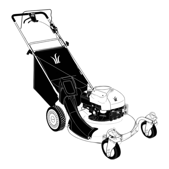
21-inch, 6-Speed
Lawn Mower
Models 999 & E999
FORM NO. 770-10076B.fm
(11/00)
Advertisement
Table of Contents

Related Manuals for MTD YARD-MAN 999


Summary of Contents for MTD YARD-MAN 999
- Page 1 Federal laws apply on federal lands. A spark arrester for the muffler is available through your nearest engine authorized service dealer or contact the service department, P.O. Box 368022 Cleveland, Ohio 44136-9722. MTD PRODUCTS INC. P.O. BOX 368022 CLEVELAND, OHIO 44136-9722 ECO # 2844 FORM NO.
-
Page 2: Table Of Contents
(Model Number) (Serial Number) Copy the model number here: Copy the serial number here: MTD PRODUCTS INC P.O. BOX 368022 CLEVELAND, OHIO 44136 CALLING CUSTOMER SUPPORT If you have difficulty assembling this product or have any questions regarding the controls, operation or maintenance of this unit, please call the Customer Support Department. -
Page 3: Important Safe Operation Practices
SECTION 1: IMPORTANT SAFE OPERATION PRACTICES WARNING: This symbol points out important safety instructions which, if not followed, could endanger the personal safety and/or property of yourself and others. Read and follow all instructions in this manual before attempting to operate this machine. Failure to comply with these instructions may result in personal injury. - Page 4 other safety protective devices in place and working. power mower. Children 14 years old and over should Never operate mower with damaged safety devices. read and understand the operation instructions and Failure to do so, can result in personal injury. safety rules in this manual and should be trained and 21.
- Page 5 meet the original equipment specifications may lead to expose moving parts or allow objects to be thrown. For improper performance and compromise safety!” safety protection, frequently check components and Mower blades are sharp and can cut. Wrap the blade or replace immediately with original equipment wear gloves, and use extra caution when servicing them.
-
Page 6: Slope Gauge
SECTION 2: SLOPE GAUGE Use this page as a guide to determine slopes where you may not operate the lawn mower safely. -
Page 7: Assembling Your Lawn Mower
SECTION 3: ASSEMBLING YOUR LAWN MOWER Unpacking Assembling Handle • Remove staples, break glue on top flaps, or cut • For shipping purposes, the grass bag was packed tape at carton end and peel along top flap to open. on top of the unit. Remove the grass bag and set it •... - Page 8 Cable Tie Inner Hole Lower Lower Handle Handle Hairpin Clip Handle Mounting Bracket Figure 7 NOTE: Make sure the drive cable is routed around the outside and above the lower handle so as not to interfere with the grass bag attachment. Figure 5 •...
-
Page 9: Know Your Lawn Mower
SECTION 4: KNOW YOUR LAWN MOWER Compare the illustrations in Figure 9 with your lawn mower to acquaint yourself with the location and working of various controls and adjustments on the equipment. Always wear safety glasses while performing any adjustments on the mower. -
Page 10: Operating Your Lawn Mower
SECTION 5: OPERATING YOUR LAWN MOWER Gas and Oil Fill-Up All Units: • Attach spark plug wire to spark plug. Make certain • Service the engine with gasoline and oil as the metal cap on the end of the spark plug wire instructed in the accompanying engine manual. - Page 11 Stopping Engine and Blade Bagging Grass Clippings • Release the blade control handle to stop the engine This mower can bag grass clippings. For that, you will and blade. have to install the grass bag on to the unit. • Remove the three wing nuts holding the mulching WARNING: The blade continues to rotate...
-
Page 12: Making Adjustments
Mulching Grass bag. See Figure 14. The bag will open and grass clippings will fall out. Empty the grass bag at a • When the mulching baffle is installed on the unit, proper disposal site. the mower is used to mulch grass clippings. If the Side-Discharge Grass Clippings mulching baffle is not already installed, you will have to remove the grass bag or side-discharge... - Page 13 Handle Height Bottom View Your mower is shipped with the handle in the higher height position.To lower the handle height for your convenience, proceed as follows. Adjustment Wheel Lower Handle Notch Figure 18 NOTE: For some operators, the drive clutch handle may not be in a comfortable position.
-
Page 14: Maintaining Your Lawn Mower
SECTION 7: MAINTAINING YOUR LAWN MOWER Cutting Blade WARNING: Always stop engine and disconnect the spark plug wire before • Periodically inspect the blade adapter for cracks, cleaning, lubricating or doing any kind of especially if you strike a foreign object. Replace maintenance work on the lawn mower. - Page 15 • Place blade bell support on blade. Make sure the with light oil. See Figure 21. The blade control must notches on the blade bell support are aligned with operate freely in both directions. the small hole in the blade. Wheels •...
- Page 16 Replacing Drive Belt • Disconnect the spark plug wire and ground it Transmission against the engine. Pulley • Drain the fuel tank or place a piece of plastic Belt beneath the cap to prevent gasoline leakage. • Place shift lever in the first position and tip the Belt Keeper mower on its side.
-
Page 17: Off-Season Storage
Lower Lower Pulley Pulley Half Half Belt Crankshaft Belt Belt Guard Pin Figure 28 Figure 26 • Pivot the control arm back to its original position • Place the new belt over the transmission pulley. and reinstall the six-speed cable into the slot. See Start the belt in the pulley groove and rotate the Figure 29. -
Page 18: Troubleshooting
SECTION 10: TROUBLE SHOOTING GUIDE Trouble Possible Cause(s) Corrective Action Engine fails to start 1. Blade control handle 1. Engage blade control handle. disengaged. 2. Connect wire to spark plug. 2. Spark plug wire disconnected. 3. Depress primer bulb slowly three 3. - Page 19 Decorative & Safety Labels...
-
Page 20: Parts List
SECTION 11: PARTS LIST FOR MODELS 999 & E999 Transmission Assembly for Reference only Pulley Assembly for Reference only NOTE: For painted parts, please refer to the list of color codes below. Please add applicable color code, wherever needed, to the part number to order a replacement part. - Page 21 Models 999 & E999 Ref. Ref. Part No. Description Part No. Description 710-0134 Scr. Carr. 1/4-20 x .62 682-9021A Caster Assembly L.H. 710-0654A Scr. TT:3/8-18:1.00 682-9024 Caster Bracket Assembly: RH 710-0703 Carriage Scr. 1/4-20 x .750 682-9026 Caster Bracket Assembly: LH 712-0397 Wing Nut 1/4-20 711-1146...
- Page 22 Model E999 42 41 NOTE: For painted parts, please refer to the list of color codes below. Please add the applicable color code, wherever needed, to the part number to order a replacement part. For instance, if a part numbered 700-xxxx is painted Yard-Man Green, the part number to order would be 700-xxxx-0665.
- Page 23 Model E999 Ref. Ref. Part No. Description Part No. Description 710-1174 Bolt Cur. Carr. 5/16-18 x 2.0 749-0907A Lower Handle 714-0104 Cotter Pin .072 x 1.12 Lg. 631-0071 Grassbag Cover w/ logo 720-0241 Knob Assembly 5/16-18 747-0939 Pivot Rod 726-0240 Strap 4.3”...
- Page 24 Model 999...
- Page 25 Model 999 Ref. Ref. Part No. Description Part No. Description 710-1174 Bolt Cur. Carr. 5/16-18 x 2.0 731-0620 Control Lever 714-0104 Cotter Pin .072 x 1.12 Lg. 746-0939 6 Spd. Cable 720-0241 Wingknob 5/16-18 746-0713 Self Prop. Cable 52” 726-0240 Strap 4.3 Lg.
- Page 26 Multi-Speed Pulley Assembly Ref. Part No. Description 746-0939 Speed Selector Cable, 53” 656-0613 Multi-Speed Pulley Assembly 710-0167 Carriage Bolt, 1/4-20 x. 5 NOTE: For painted parts, please refer to 710-0896 Self-Tapping Screw, 1/4-20 x .625 the list of color codes below. Please add 711-1114 Pivot Shaft applicable...
- Page 27 Transmission Assembly IMPORTANT: For a proper working machine, use Factory Approved Parts. V-BELTS are specially designed to engage and disengage safely. A substitute (non OEM) V-Belt can be Ref. dangerous by not disengaging completely. Part No. Description 712-3025 Hex Jam Nut, 5/16-24 736-0425 Bell Wash.
- Page 28 MANUFACTURER’S LIMITED WARRANTY FOR: c. Routine maintenance items such as lubricants, filters, The limited warranty set forth below is given by MTD blade sharpening and tune-ups, or adjustments such PRODUCTS INC (“MTD”) with respect to new merchan- as brake adjustments, clutch adjustments or deck dise purchased and used in the United States, its posses- adjustments;...