Advertisement
Quick Links
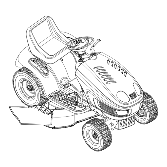
Operator's Manual
Auto Drive
Lawn Tractors
Models 604G & 604H
IMPORTANT: Read safety rules and instructions carefully before operating equipment.
Warning:
This unit is equipped with an internal combustion engine and should not be used on or near any unimproved forest-covered,
brush-covered or grass-covered land unless the engine's exhaust system is equipped with a spark arrester meeting applicable local or state
laws (if any). If a spark arrester is used, it should be maintained in effective working order by the operator. In the State of California the above
is required by law (Section 4442 of the California Public Resources Code). Other states may have similar laws. Federal laws apply on federal
lands. A spark arrester for the muffler is available through your nearest engine authorized service dealer or contact the service department,
P.O. Box 361131 Cleveland, Ohio 44136-0019.
MTD LLC, P.O. BOX 361131 CLEVELAND, OHIO 44136-0019
PRINTED IN U.S.A.
FORM NO. 770-10448D.fm
(11/2003)
Advertisement

Related Manuals for MTD Yard-Man 604G


Summary of Contents for MTD Yard-Man 604G
- Page 1 A spark arrester for the muffler is available through your nearest engine authorized service dealer or contact the service department, P.O. Box 361131 Cleveland, Ohio 44136-0019. MTD LLC, P.O. BOX 361131 CLEVELAND, OHIO 44136-0019 PRINTED IN U.S.A. FORM NO. 770-10448D.fm...
-
Page 2: Table Of Contents
This information will be necessary to use the manufacturer’s web site and/or help from the Customer Support Department or an authorized service dealer. (Model Number) Copy the model number here: (Serial Number) Copy the serial number here: MTD LLC P. O. BOX 361131 CLEVELAND,OH 44136 www.yardman.com 330-220-4683 800-800-7310 CUSTOMER SUPPORT Please do NOT return the unit to the retailer from where it was purchased, without first contacting Customer Support. -
Page 3: Important Safe Operation Practices
SECTION 1: IMPORTANT SAFE OPERATION PRACTICES WARNING: This symbol points out important safety instructions which, if not followed, could endanger the personal safety and/or property of yourself and others. Read and follow all instructions in this manual before attempting to operate this machine. Failure to comply with these instructions may result in personal injury. - Page 4 27. Use only accessories and attachments approved for this Do not tow heavy pull behind attachments (e.g. loaded machine by the machine manufacturer. Read, dump cart, lawn roller, etc.) on slopes greater than 5 understand and follow all instructions provided with the degrees.
- Page 5 Never fill containers inside a vehicle or on a truck serviced professionally by your Troy-Bilt dealer. or trailer bed with a plastic liner. Always place Check brake operation frequently as it is subjected to containers on the ground away from your vehicle wear during normal operation.
- Page 6 SECTION 2: SLOPE GAUGE...
-
Page 7: Tractor Set-Up
SECTION 3: TRACTOR SET-UP NOTE: This manual covers specifications of two models. Please follow instructions and parts numbers pertaining to your tractor only. Attaching the Battery Cables NOTE: If these cables are already attached, proceed to “Attaching Steering Wheel.” The positive battery terminal is marked Pos. IMPORTANT: (+). - Page 8 WARNING: Before operating this machine, make sure the seat is engaged in the seat stop, stand behind the machine and pull back on seat until fully engaged into stop. 2. Slide the seat slightly rearward in the seat pivot bracket, lining up the rear slots in the pivot bracket with the remaining two holes in the seat’s base.
-
Page 9: Operation
SECTION 4: OPERATION Know the Controls Read this owner’s manual and safety rules before operating your lawn mower. Compare figure below with your lawn tractor to learn about the loction and purpose of various controls and adjustments. Save this manual for future reference. - Page 10 Throttle Control Lever The throttle control lever controls the speed of the engine. When set in a given position, the throttle will maintain a uniform engine speed. Fast When operating the tractor with the cutting deck engaged, IMPORTANT: throttle control lever must always be in the FAST (rabbit) position. Choke Control The choke control can be found on the left side of the dash panel and is activated by pulling the knob outward.
- Page 11 Headlights • To turn on the headlights, rotate the same ignition key from ON position to ON/LIGHTS position of the ignition switch. • To turn off the headlights, rotate the ignition key from ON/LIGHTS position to either ON position (to leave the engine running) or OFF position (to shut the engine off).
- Page 12 • To change to the reverse direction when operating with cruise control, depress the brake pedal to disengage the cruise control and bring the tractor to a complete stop. Then place the shift lever in the REVERSE position and depress the drive pedal. Seat Adjustment Lever To adjust the seat forward or backward, loosen the two seat adjustment knobs and reposition the seat to the desired position.
- Page 13 Starting the Engine NOTE: Refer to the TRACTOR SET-UP on page 7 manual for gasoline and oil fill-up instructions. IMPORTANT 1. Insert the tractor key into the ignition switch. 2. Disengage the PTO (Blade Engage) lever. 3. Engage the tractor’s parking brake. 4.
- Page 14 • For best results it is recommended that the first two laps be cut with the discharge thrown towards the center. After the first two laps, reverse the direction to throw the discharge to the outside for the balance of cutting. This will give a better appearance to the lawn.
-
Page 15: Making Adjustments
SECTION 5: MAKING ADJUSTMENTS WARNING: Never attempt to make any adjustments while the engine is running, except where specified in the operator’s manual.Disconnect spark plug wire(s) and ground against the engine before performing any adjustments, repairs or maintenance. Seat WARNING: Before operating this machine, Seat Knob make sure the seat is engaged in the seat stop,... - Page 16 1. With the tractor parked on a firm, level surface, place Lock Nut the deck lift lever in the top notch (highest position) and rotate the blade nearest the discharge chute so that it is parallel with the tractor. Deck 2.
- Page 17 SECTION 6: MAINTAINING YOUR LAWN TRACTOR WARNING: Before performing any maintenance or repairs, disengage PTO, move shift lever into neutral position, set parking brake, stop engine and remove key to prevent unintended starting. Engine Refer to the engine manual for engine maintenance instructions. •...
- Page 18 tractor and/or its serviceability. WARNING: Before servicing, repairing, or inspecting, always disengage PTO, move shift lever into neutral position, set parking brake, stop engine and remove key from tractor to prevent unintended starting. Tire Pressure Never exceed the maximum inflation pressure shown on the sidewall of the tire. IMPORTANT: •...
- Page 19 4. Connect the other end of the negative (-) cable to the engine block of the stalled tractor, away from the battery, and stand back. 5. Start the stalled tractor and leave it running to charge the battery. 6. Disconnect the negative (-) jumper cable from the tractor. 7.
- Page 20 Each cutting blade edge has to be ground equally to maintain proper blade balance. A poorly balanced IMPORTANT: blade will cause excessive vibration, may damage the tractor and/or result in personal injury. Hex Flange Nut Wood Block Blade separation Worn blade edge Wind Wing Sharpen edge evenly Spindle Assembly...
- Page 21 When removing the battery, disconnect the NEGATIVE (Black) wire from its terminal first, followed by IMPORTANT: the POSITIVE (Red) wire. Re-install in reverse order. Upper Drive Belt 1. Locate the transmission idler pulley on the upper drive belt by looking through the battery tray opening. See Figure 15.
- Page 22 After replacing the drive belts, adjust the drive Idler Place Wrenches Here pedal on your tractor as follows: Adj. Rod 1. Locate the speed control assembly on the underside of the steering support bracket. See Neutral Figure 17. Return 2. Remove both hairpin clips from the pin which is Bracket fastened to the speed control assembly (be careful not to lose the small flat washers found on the pin).
- Page 23 4. Remove the PTO belt from around the engine pulley and the PTO idler pulley. 5. Grasp the deck idler pulley and pivot it toward the left side of the deck to relieve tension on the deck belt. 6. Remove the belt from around all pulleys, including the deck idler pulley. 7.
-
Page 24: Attachments & Accessories
SECTION 7: OFF-SEASON STORAGE WARNING: Never store the machine or fuel container indoors where there is an open flame, spark or pilot light such as on water heater, furnace, clothes dryer or other gas appliance. • Clean and lubricate the tractor as instructed on page 17 before storing for an extended period. WARNING: Drain fuel only into an approved container outdoors, away from an open flame. - Page 25 SECTION 8: TROUBLESHOOTING Trouble Possible Cause(s) Corrective Action Engine fails to start PTO lever/knob engaged. Place PTO lever/knob in OFF position. Parking brake not engaged. Engage parking brake. Spark plug wire(s) disconnected. Connect wire(s) to spark plug. Throttle control lever not in correct Place throttle lever to CHOKE position.
-
Page 26: Illustrated Parts List
SECTION 9: PARTS LIST FOR MODELS 604G & 604H... - Page 27 Models 604G & 604H REF. PART REF. PART DESCRIPTION DESCRIPTION 710-3015 Hex Cap Screw, 1/4-20 x .75 710-0599 Self-tapping Screw, 1/4-20 x .50 710-0599 Self-tapping Screw, 1/4-20 x .5 710-1017 Torx Self-tapping Screw, 1/4-14 x .625 712-0324 Hex Lock Nut, 1/4-20 710-3217 Torx Screw, #8-32 x .375 710-0895...
- Page 28 Models 604G & 604H...
- Page 29 Models 604G & 604H Ref. Part Description 747-1130B Deck Stabilizer Rod 683-0197B Lift Shaft Assembly 711-0332 Clevis Pin, .5 x .78 712-0206 Hex Nut, 1/2-13 712-0431 Flange Lock Nut, 3/8-16 712-0429 Lock Nut, 5/16-18 712-3083 Hex Nut, 1/2-13 714-0104 Internal Cotter Pin 714-0145 Internal Cotter Pin 716-0106...
- Page 30 Models 604G & 604H...
- Page 31 Models 604G & 604H Ref. Part Description 710-1260A Self-tapping Screw, 5/16-18 x .75 710-0604A Self-tapping Screw, 16-18 x .625 783-0726B RH Pivot Support Bracket 783-0727A LH Pivot Support Bracket 783-0728 Pivot Bar Bracket 710-0514 Hex Cap Screw, 3/8-16 x 1 (Grade 5) 711-1408 RH Drag Link 711-1409A...
- Page 32 Models 604G & 604H IMPORTANT: For a proper working machine, use Factory Approved Parts. V-belts are designed to engage and disengage safely. A substitute (non OEM) V-belt can be dangerous by not disengaging completely.
- Page 33 Models 604G & 604H Ref. Part Ref. Part Description Description 17840 Mounting Bracket 710-0726 AB Screw 5/16-12 x 0.75 618-04133 Drive Assembly 710-1260A LD Screw 5/16-18 x 0.75 618-04147 Variable Spd. Pulley Assembly 710-1611B TT Screw 5/16-18 x 0.75 647-04020 Shift Lever Assembly 711-04159 710-0607...
- Page 34 Models 604G & 604H...
- Page 35 Models 604G & 604H Ref. Part Description 732-0614 Ring, Wire 716-0231 Ring, E Type, .750 736-0336 Flat Washer, 5/8 x 1.0 x .030* 736-0337 Flat Washer, 5/8 x 1.0 x .040* 736-0349 Flat Washer, 5/8 x 1.0 x .020* 736-0335 Washer, Thrust .635 x 1.26 x .06 710-1325 Self-tapping Screw, 1/4-20 x 1.625...
- Page 36 Models 604G & 604H 56 57 20 42 Model 604H Model 604G...
- Page 37 Models 604G & 604H Ref. Part No. Description Ref. Part No. Description 17962 Switch Plate 747-1286A Rod: Belt Keeper 647-0064 Lever Assembly: PTO Engage 748-0415B Spacer 683-0450 Plate Assembly: PTO Engage 750-0956 Spacer 710-0224 AB Screw #10-16 x 0.5 756-0627B Idler Pulley 710-0276 Carriage Screw: Special...
- Page 38 Models 604G & 604H (for choke) REF. PART DESCRIPTION 710-0227 Self-tapping Screw, #8-18 x .5 710-0599 Self-tapping Screw, 1/4-20 x .5 710-0604A Self-tapping Screw, 5/16-18 x .625 710-1237 Screw, #10-32 x .625 710-1314A Socket Cap Screw, 5/16-18 x .625 710-1315 Self-tapping Screw, 3/8-16 x 1.25 712-3017 Hex Nut, 3/8-16...
- Page 39 Models 604G & 604H YEL/WHT ORG/BLK...
- Page 40 Model 604G...
- Page 41 Model 604G Ref. Part No. Description Ref. Part No. Description 711-04069 Grass Catcher Pin, 1/4-20 736-0270 Bell Washer, .265 x .75 x .062 618-0565 Spindle Assy., 5.75 Dia. w/ Fitting 738-0373 Shoulder Screw, .498 x 1.53 683-0198G 42-inch Deck Shell 741-0524 Bearing, .625 x 1.574 x .470 683-0254...
- Page 42 Model 604H 25 14...
- Page 43 Model 604H Ref. Part No. Description Ref. Part No. Description 736-0760 Lock Washer 618-04137 Pulley-Spindle Assembly 737-3007 Grease 683-0254 Deck Hanger Bracket Assembly 738-0372B Shoulder Spacer 683-04103 Deck Assembly 738-0373 Shoulder Screw 3/8-16 x 1.5 710-0347 Hex Bolt 3/8-16 x 1.75 742-0611A Blade 16.28 Lg.: Three-in-One 710-0514...
- Page 44 MANUFACTURER’S LIMITED WARRANTY FOR: The limited warranty set forth below is given by MTD LLC with MTD does not extend any warranty for products sold or respect to new merchandise purchased and used in the exported outside of the United States, its possessions United States, its possessions and territories.