Advertisement
Don't be a fool by throwing away this manual! Grab a couple brews, sit on your butt & READ THIS! You
will NOT be able to set this amplifier properly unless you thoroughly understand the sophisticated pre-
amp section of the amplifier. You are now the owner of what may be the finest car audio amplifier ever
made. Please read this manual in its entirety. These brand new, long-awaited Reference amplifiers are
the finest amplifiers we have ever produced and they WILL change the way you hear and feel music...
REF1.500
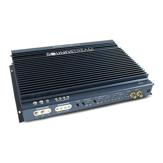
REF2.370
REF1.1000
REF2.640
REF4.400
REF4.760
REF4.920
Advertisement
Table of Contents

Related Manuals for Soundstream Reference Series 640


Summary of Contents for Soundstream Reference Series 640
- Page 1 Don’t be a fool by throwing away this manual! Grab a couple brews, sit on your butt & READ THIS! You will NOT be able to set this amplifier properly unless you thoroughly understand the sophisticated pre- amp section of the amplifier. You are now the owner of what may be the finest car audio amplifier ever made.
-
Page 2: Table Of Contents
Table of Contents Reference Lives Features Specifications Installation Controls and Terminals Control Definitions System Diagrams Subwoofer Diagrams Troubleshooting 8-10 11-13 14-17 18-19... -
Page 3: Reference Lives
Reference Lives! Can you believe that it has been over a decade since the legendary Soundstream Reference amps graced the car audio industry?! Maybe you bought this amplifier because the best amplifier you ever had was a Reference from back in the day. -
Page 4: Features
Features In the 80s, it became popular to use acronyms for amplifier features and technologies. In some cases, these acronyms were nothing more than fancy words put together cleverly to form an acronym not worth its weight in poop! Sales people memorized the silly acronyms but rarely knew what the feature encompassed. - Page 5 Pulse Width Modulated • Large TO218 MOSFET Transistors • High Volume, Low ESR Capacitance Banks Compensate Power Supply Ripple Currents • Extra Low Current Drive Stage Increases Efficiency & Sound Clarity • Individually Regulated Preamp/Crossover Power Supplies Ensure Signal Purity •...
-
Page 6: Specifications
REF2.370 S P E C I F I C A T I O N S Channels RMS Power @ 4Ω, 14.4V RMS Power @ 2Ω, 14.4V RMS Power @ 4Ω Bridged, 14.4V RMS Power @ 1Ω, 14.4V Total Harmonic Distortion (4Ω power) Frequency Response 15-50kHz Signal-to-Noise Ratio (4Ω... -
Page 7: Installation
Installation Before installing any audio equipment, it is good practice to disconnect the ground terminal on the battery to avoid dam- age to the vehicle or audio equipment. Failure to do this means you’re a few brews short of a 6-pack and you probably already acquired the nickname of “Sparky”... -
Page 8: Controls And Terminals
Controls and Terminals REF2.370 REF2.640... - Page 9 REF4.400 REF4.760 REF4.920...
-
Page 10: Controls And Terminals
Controls and Terminals REF1.500 REF1.1000... -
Page 11: Control Definitions
Pass for the tweeters at 4kHz. The low pass, if it as two ranges, may be from 50-800Hz which is not high enough. By using the multiplier switch, that same control can change the range from 50Hz-800Hz to 250Hz- 4kHz. If this doesn’t make sense and you do not understand frequencies clearly, PLEASE TAKE YOUR AMP TO A PROFESSIONAL SOUNDSTREAM DEALER! - Page 12 Setting the control above the proper point may cause damage to the amplifier and speakers, and can result in poor sound quality and overall undesirable results… RCA Signal Inputs – Ummm… If you do not know what goes here, get over to your local Soundstream dealer immediately!
- Page 13 Phase Switch – This switch changes the phase of the woofer from 0 to 180 degrees. Subsonic – Part of the Hawkins circuit, this is a patented circuit developed by Soundstream many years ago. Haw- kins has 2 controls but 3 functions. One of the controls is the boost and it is from 0-10dB. The second control is the frequency.
-
Page 14: System Diagrams
System Diagrams 2 CHANNEL SYSTEM DESIGN #1 REF2.370 / REF2.640 2 - 4 Ohms 2 CHANNEL SYSTEM DESIGN #2 REF2.370 / REF2.640 4 - 8 Ohms 2 - 4 Ohms... - Page 15 4 - 8 Ohms *Inductor and Capacitor passive crossovers must be at the same frequency or underlapped, but never overlapped. If this does not make sense, drop what you are doing and take your car to a professional Soundstream dealer!
- Page 16 2 - 4 Ohms 2 - 4 Ohms 2 - 4 Ohms 2 - 4 Ohms...
- Page 17 *Inductor and Capacitor passive crossovers must be at the same frequency or underlapped, but never overlapped. If this does not make sense, drop what you are doing and take your car to a professional Soundstream dealer! 2-4 Ohms SUB WOOFER...
-
Page 18: Subwoofer Diagrams
Subwoofer Wiring Diagrams 1-2 Ohms Series-Parallel / Three Dual 2 Ohm Net Impedance = 1.33 Ohms Parallel / Three Single 4 Ohm Net Impedance = 1.33 Ohms Series-Parallel / Two Dual 2 Ohm Net Impedance = 2 Ohms Parallel / Two Dual 4 Ohm Net Impedance = 1 Ohm Parallel / Two Single 4 Ohm Net Impedance = 2 Ohm... - Page 19 Subwoofer Wiring Diagrams Series-Parallel / Four Dual 2 Ohm Net Impedance = 1 Ohm Series-Parallel / Four Dual 4 Ohm Net Impedance = 2 Ohm Series-Parallel / Four Single 4 Ohm Net Impedance = 1 Ohm...
-
Page 20: Troubleshooting
Troubleshooting SYMPTOM Is the Status LED illuminated GREEN? NO? NO SOUND Is the Status LED illuminated GREEN? Yes? No power to power wire Poor Ground AMP NOT SWITCHING ON Does remote wire have +12V Check fuses Check speaker wire NO SOUND ON ONE CHANNEL Check RCAs AMP SHUTS DOWN Check speaker load...