Table of Contents
Advertisement
Advertisement
Table of Contents

Related Manuals for Soundstream D-Tower DTR1.1700


Summary of Contents for Soundstream D-Tower DTR1.1700
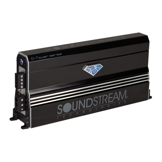
- Page 1 D-Tower Amplifier Series Owner’s Manual...
- Page 2 Date of Purchase____________________ Installation Shop____________________ Installation Date ____________________ CAUTION ! Prolonged listening at extremely high levels may result in hearing loss. Even though your new Soundstream D- Tower Amplifier sounds better than anything you've heard, exercise caution to prevent hearing damage .
- Page 3 FEATURES THE WORLD’S FIRST VERTICAL CAR AMPLIFIER. COMPACT SIZE AND TINY FOOTPRINT. SINGLE END CABLE WIRING. DOUBLE SIDE PCB AND SMD COMPONENTS. FULL MOSFET DESIGN. LPF AND SUBSONIC CROSSOVER. ADJUSTABLE BASSBOOST FREQUENCY AND LEVEL. INFINITELY VARIABLE PHASE CONTROL. 1-OHM LOAD STABLE FOR ALL CLASS-D MODELS (EXCEPT FOR LARGEST MODEL WHICH IS .5-OHM LOAD STABLE).
-
Page 4: Volt Power
CONTROL FUNCTIONS 1. SPEAKERS Connect speakers/subwoofers to these terminals. Be sure to check wire for proper polarity. Never connect the speaker cables to chassis ground. 2. +12 Volt Power Connect this terminal through a FUSE or CIRCUIT BREAKER to the positive terminal of the vehicle battery or the positive terminal of an isolated audio system battery. -
Page 5: Phase Control
CONTROL FUNCTIONS 7. REMOTE Connect the remote controller to control the subwoofer amplifier volume from the driver seat location, for ease of adjustment during playing. 8. LEVEL Control The level control will match the amplifiers sensitivity to the source units signal voltage. -
Page 6: Control Functions
CONTROL FUNCTIONS 14. X-over mode and frequency Control (Monoblocks) These controls allow control over the frequencies played for the rear channels. There is an option for Low/BandPass, Full Range or High Pass. In HP mode, the frequency range is from 15Hz to 500Hz. In LP mode, the frequency range can be switched from 50Hz to 800Hz, or 250Hz to 4kHz. - Page 7 . MOUNTING AMPLIFIER 1.Soundstream D-Tower amplifiers can be installed vertical or horizontal. Plan the installation method and find a suitable location with sufficient air circulation.
-
Page 8: Panel Layout
PANEL LAYOUT Fig 1. Mono amplifier panel layout DTR1.900D / DTR1.1400.D / DTR1.1700D / DTR1.2200D / DTR1.3400D... - Page 9 PANEL LAYOUT Fig 2. 4-ch amplifier panel layout DTR4.500...
-
Page 10: Connecting The Amplifier
CONNECTING THE AMPLIFIER 1. Select cable and fuse according to the following table. MODEL DTR1.900D DTR1.1400D CABLE FUSE 100A 2. Connect the amplifiers ground cable to a close, bare metal part of the frame or chassis. Use a nut and bolt, NOT a screw! The ground cable must be at least the same size as the +12volt cable. - Page 11 WIRING DIAGRAM Fig 5. Mono amplifier wiring (High level input mode) Source Unit / Original Amplifier Speaker signal Fig 6. Mono amplifier wiring (multi woofers) Source Unit REMOTE signal FUSE ON/OFF control signal *Equivalent parallel woofer load cannot be less than the minimum load rating. The 2 negative terminals are paralleled inside the amplifiers, as are the 2 positive terminals.
-
Page 12: Channel Mode
WIRING DIAGRAM Fig 7. DTR4.500 wiring (4-channel mode) Source Unit RCA signals REMOTE signal Fig 8. DTR4.500 wiring (3-channel mode) Source Unit RCA signals REMOTE signal 2-Ohm to 4-Ohm 2-Ohm to 4-Ohm FUSE FRONT INPUT 2-Ohm to 4-Ohm 2-Ohm to 4-Ohm FUSE FRONT INPUT... - Page 13 WIRING DIAGRAM Fig 9. DTR4.500 wiring (active x-over mode) Source Unit RCA signals REMOTE signal Fig 10. DTR4.500 wiring (High level input mode) Source Unit / Original amplifier Speaker signal Speaker signal Tweeter Tweeter FUSE FRONT INPUT 2-Ohm to 4-Ohm 2-Ohm to 4-Ohm FUSE FRONT...
-
Page 14: Troubleshooting
TROUBLE SHOOTING Symptom Possible Remedy Amplifier Check to make sure you have a good ground connection. will not Check that there is battery power on the (+)terminal . power up Check all fuses, replace if necessary . Make sure that the Protection LED is not illuminated. Protection Check for short circuits on speaker leads. -
Page 15: Specifications
SPECIFICATIONS Model DTR1.900 0.5 Ohm 1 Ohm 2 Ohm 4 Ohm Input Level High Level Input Frequency Response X-over Type Subsonic / HPF Bass Boost Frequency Bass Boost Level Damping Factor S/N Ratio Phase Shift Minimum Load Voltage Protection Components & PCB Bass Remote Height Width...