Table of Contents
Advertisement
Quick Links
Advertisement
Table of Contents
Troubleshooting

Related Manuals for Miller Big Blue 350 PipePro


Summary of Contents for Miller Big Blue 350 PipePro
- Page 1 2010−09 Processes Processes MIG (GMAW) Welding Flux Cored (FCAW) Welding Stick (SMAW) Welding TIG (GTAW) Welding Air Carbon Arc (CAC-A) Cutting and Gouging Description Engine Driven Welding Generator Big Blue 350 PipePro File: Engine Drive Visit our website at www.MillerWelds.com...
- Page 2 We know you don’t have time to do it any other way. That’s why when Niels Miller first started building arc welders in 1929, he made sure his products offered long-lasting value and superior quality.
-
Page 3: Table Of Contents
TABLE OF CONTENTS SECTION 1 − SAFETY PRECAUTIONS − READ BEFORE USING ....... . . 1-1. - Page 4 TABLE OF CONTENTS 6-5. Remote Voltage/Amperage Control ............6-6.
-
Page 5: Section 1 − Safety Precautions − Read Before Using
SECTION 1 − SAFETY PRECAUTIONS − READ BEFORE USING rom_2010−03 Protect yourself and others from injury — read, follow, and save these important safety precautions and operating instructions. 1-1. Symbol Usage DANGER! − Indicates a hazardous situation which, if Indicates special instructions. not avoided, will result in death or serious injury. - Page 6 D Do not weld on closed containers such as tanks, drums, or pipes, FUMES AND GASES can be hazardous. unless they are properly prepared according to AWS F4.1 (see Safety Standards). Welding produces fumes and gases. Breathing these D Do not weld where the atmosphere may contain flammable dust, fumes and gases can be hazardous to your health.
-
Page 7: Engine Hazards
1-3. Engine Hazards EXHAUST SPARKS can cause fire. BATTERY EXPLOSION can injure. D Do not let engine exhaust sparks cause fire. D Always wear a face shield, rubber gloves, and protective clothing when working on a battery. D Use approved engine exhaust spark arrestor in required areas —... -
Page 8: Hydraulic Hazards
1-4. Hydraulic Hazards D HYDRAULIC FLUID is FLAMMABLE−−do not work on hydraulics HYDRAULIC EQUIPMENT can injure near sparks or flames; do not smoke near hydraulic fluid. or kill. D Reinstall doors, panels, covers, or guards when servicing is D Incorrect installation or operation of this unit finished and before starting unit. -
Page 9: Additional Symbols For Installation, Operation, And Maintenance
HOT METAL from air arc cutting and MOVING PARTS can injure. gouging can cause fire or explosion. D Keep away from moving parts such as fans, D Do not cut or gouge near flammables. belts and rotors. D Watch for fire; keep extinguisher nearby. D Keep all doors, panels, covers, and guards closed and securely in place. -
Page 10: California Proposition 65 Warnings
WELDING WIRE can injure. H.F. RADIATION can cause interference. D Do not press gun trigger until instructed to do D High-frequency (H.F.) can interfere with radio navigation, safety services, computers, and communications equipment. D Do not point gun toward any part of the body, other people, or any metal when threading D Have only qualified persons familiar with welding wire. -
Page 11: Principal Safety Standards
1-8. Principal Safety Standards Safety in Welding, Cutting, and Allied Processes, ANSI Standard Z49.1, 25 West 43rd Street, New York, NY 10036 (phone: 212-642-4900, web- from Global Engineering Documents (phone: 1-877-413-5184, website: site: www.ansi.org). www.global.ihs.com). Standard for Fire Prevention During Welding, Cutting, and Other Hot Safe Practices for the Preparation of Containers and Piping for Welding Work, NFPA Standard 51B, from National Fire Protection Association, and Cutting, American Welding Society Standard AWS F4.1, from Glob-... -
Page 12: Section 2 − Consignes De Sécurité − Lire Avant Utilisation
SECTION 2 CONSIGNES DE SÉCURITÉ − LIRE AVANT − UTILISATION fre_rom_2010−03 Pour écarter les risques de blessure pour vous−même et pour autrui — lire, appliquer et ranger en lieu sûr ces consignes relatives aux précautions de sécurité et au mode opératoire. 2-1. - Page 13 D Porter un casque de soudage approuvé muni de verres filtrants LES PIÈCES CHAUDES peuvent approprié pour protéger visage et yeux pour protéger votre visage provoquer des brûlures. et vos yeux pendant le soudage ou pour regarder (voir ANSI Z49.1 et Z87.1 énuméré...
-
Page 14: Dangers Existant En Relation Avec Le Moteur
D Placer les bouteilles debout en les fixant dans un support station- Les CHAMPS ÉLECTROMAGNÉTIQUES (CEM) naire ou dans un porte-bouteilles pour les empêcher de tomber ou peuvent affecter les implants médicaux. de se renverser. D Tenir les bouteilles éloignées des circuits de soudage ou autres D Les porteurs de stimulateurs cardiaques et circuits électriques. -
Page 15: Dangers Liés À L'hydraulique
D Mettre des lunettes de sécurité et des gants, placer un torchon sur LES ÉTINCELLES À L’ÉCHAPPEMENT le bouchon du radiateur. peuvent provoquer un incendie. D Dévisser le bouchon légèrement et laisser la vapeur s’échapper avant d’enlever le bouchon. D Empêcher les étincelles d’échappement du moteur de provoquer un incendie. -
Page 16: Dangers Liés À L'air Comprimé
un médecin familiarisé avec ce type de blessure, faute de quoi LES PIÈCES ET LIQUIDES CHAUDS la gangrène pourrait apparaître. peuvent provoquer des brûlures. Les PIÈCES MOBILES peuvent causer D Ne pas toucher les pièces chaudes à main nue des blessures. ni laisser des liquides chauds entrer en contact avec la peau. -
Page 17: Dangers Supplémentaires En Relation Avec L'installation, Le Fonctionnement Et La Maintenance
D Remettre en place les portes, panneaux, recouvrements ou PRESSION D’AIR RÉSIDUELLE dispositifs de protection à la fin des travaux d’entretien et avant ET DES FLEXIBLES QUI FOUETTENT de mettre le moteur en marche. risquent de provoquer des blessures. D Détendre la pression pneumatique des outils et PIÈCES CHAUDES peuvent... -
Page 18: Proposition Californienne 65 Avertissements
D Demander seulement à des personnes qualifiées familiarisées LES CHARGES ÉLECTROSTATI- avec des équipements électroniques de faire fonctionner l’installa- QUES peuvent endommager les tion. circuits imprimés. D L’utilisateur est tenu de faire corriger rapidement par un électricien qualifié les interférences résultant de l’installation. D Établir la connexion avec la barrette de terre avant de manipuler des cartes ou des pièces. -
Page 19: Principales Normes De Sécurité
2-8. Principales normes de sécurité Safety in Welding, Cutting, and Allied Processes, ANSI Standard Z49.1, 25 West 43rd Street, New York, NY 10036 (phone: 212-642-4900, web- from Global Engineering Documents (phone: 1-877-413-5184, website: site: www.ansi.org). www.global.ihs.com). Standard for Fire Prevention During Welding, Cutting, and Other Hot Safe Practices for the Preparation of Containers and Piping for Welding Work, NFPA Standard 51B, from National Fire Protection Association, and Cutting, American Welding Society Standard AWS F4.1, from Glob-... -
Page 20: Section 3 − Definitions
SECTION 3 − DEFINITIONS 3-1. Symbols And Definitions Fast (Run, Weld/ Stop Engine Slow (Idle) Start Engine Power) Starting Aid Engine Oil Battery (Engine) Engine Oil (Preheat) Pressure Check Injectors/ Check Valve Protective Earth Fuel Pump Clearance (Ground) Certified/Trained Positive Negative Welding Arc Mechanic... -
Page 21: Section 4 − Specifications
SECTION 4 − SPECIFICATIONS 4-1. Weld, Power, And Engine Specifications Maximum Welding Weld Output Rated Welding Open- Auxiliary Power Fuel Engine Rat- Mode Range Output Circuit Rating Capacity Voltage Stick 325 A, 33 Volts DC 100% Duty Cycle 350A, 34 Volts DC Generator 60% Duty Cycle Single-Phase,... -
Page 22: Cc Volt-Ampere Curves
4-3. CC Volt-Ampere Curves The volt-ampere curves show the minimum and maximum voltage and amperage output capabilities of the welding generator. Curves of all other settings fall between the curves shown. A. Stick Mode DC Amperes B. TIG Mode DC Amperes 247 987-A / 247 988-A OM-244 620 Page 18... -
Page 23: Fuel Consumption
4-4. Fuel Consumption The curve shows typical fuel use under weld or power loads. 2.00 1.75 1.50 1.25 1.00 0.75 0.50 0.25 IDLE 0.00 DC Weld Amperes At 100% Duty Cycle 247 984-A 4-5. Duty Cycle And Overheating 100% Duty Cycle Duty Cycle is percentage of 10 min- utes that unit can weld at rated load without overheating. -
Page 24: Ac Generator Power Curve
4-6. AC Generator Power Curve The AC power curve shows the generator power in amperes. AC Amperes 247 989-A OM-244 620 Page 20... -
Page 25: Section 5 − Installation
SECTION 5 − INSTALLATION 5-1. Serial Number And Rating Label Locations The serial number and rating information for this product is located on the front. Use rating label to determine input power requirements and/or rated output. For future reference, write serial number in space provided on back cover of this manual. 5-2. -
Page 26: Mounting Welding Generator
5-3. Mounting Welding Generator Do not weld on base. Weld- ing on base can cause fuel tank fire or explosion. Weld only on the four mounting brackets or bolt unit down. Supporting The Unit NOTICE − Do not mount unit by supporting the base only at the four mounting brackets. -
Page 27: Grounding Generator To Truck Or Trailer Frame
5-4. Grounding Generator To Truck Or Trailer Frame GND/PE rot_grnd2 2010−04 − 800 652-D welding generator from the vehicle Equipment Grounding Terminal (On Always ground generator frame to Front Panel) frame. Always connect a ground vehicle frame to prevent electric shock and static electricity hazards. -
Page 28: Activating The Dry Charge Battery (If Applicable)
5-6. Activating The Dry Charge Battery (If Applicable) Always wear a face shield, rubber gloves and protective clothing when working on a battery. Remove battery from unit. Vent Caps Sulfuric Acid Electrolyte (1.265 Specific Gravity) Well Fill each cell with electrolyte to bottom of well (maximum). -
Page 29: Engine Prestart Checks
5-8. Engine Prestart Checks Check radiator coolant level when fluid is low in recovery tank. Full Full Diesel Capacity: 10 qt (9.5 L) Coolant Recovery Tank Hot Full Cold Full Full 907 428−2 / 907 428−3 Engine stops if fuel level is low. freeze to mixture if using the unit in tempera- Check all engine fluids daily. -
Page 30: Weld Output Terminals
5-9. Weld Output Terminals 246 345 Negative (−) Weld Output Terminal For Direct Current Electrode Negative feeder cable to Positive (+) terminal and (DCEN), reverse cable connections. work cable to Negative (−) terminal. Positive (+) Weld Output Terminal TIG (GTAW) Welding For Direct Current Electrode Negative Use Process switch to select type of weld For TIG welding Direct Current Electrode... -
Page 31: Selecting Weld Cable Sizes
**Weld cable size (AWG) is based on either a 4 volts or less drop or a current density of at least 300 circular mils per ampere. ( ) = mm for metric use ***For distances longer than those shown in this guide, call a factory applications rep. at 920-735-4505 (Miller) or 1-800-332-3281 (Hobart) Ref. S-0007-G 2009−08 OM-244 620 Page 27... -
Page 32: Connecting To Remote 14 Receptacle Rc14
5-12. Connecting To Remote 14 Receptacle RC14 Socket* Socket Information Not all models have contactor control. See description of front panel controls and circuit diagram. 24 volts AC. Protected by supplementary protector. 24 VOLTS AC Contact closure to A completes 24 volt AC contactor control circuit. - Page 33 Notes MATERIAL THICKNESS REFERENCE CHART 24 Gauge (.025 in) 22 Gauge (.031 in) 20 Gauge (.037 in) 18 Gauge (.050 in) 16 Gauge (.063 in) 14 Gauge (.078 in) 1/8 in (.125 in) 3/16 in (.188 in) 1/4 in (.25 in) 5/16 in (.313 in) 3/8 in (.375 in) 1/2 in (.5 in)
-
Page 34: Section 6 − Operating Welding Generator
SECTION 6 − OPERATING WELDING GENERATOR 6-1. Front Panel Controls (See Section 6-2) 246 345-B / 907 428−1 OM-244 620 Page 30... -
Page 35: Description Of Front Panel Controls (See Section 6-1)
6-2. Description Of Front Panel Controls (See Section 6-1) Engine Starting Controls sist with arc starts and help prevent the elec- Normal engine temperature is 180 - 2035 trode from sticking while welding (see volt- Preheat Switch F (82 - 955 C). Normal oil pressure is 30 ampere curves in Section 4-3). -
Page 36: Process/Contactor Switch
6-3. Process/Contactor Switch Process/Contactor Switch Weld output terminals are ener- gized when Process/Contactor switch is in an Electrode Hot position and the engine is run- ning. Use switch to select weld process and weld output on/off control (see table be- low). -
Page 37: Lift-Arct Tig With Auto-Stopt
6-4. Lift-Arct TIG With Auto-Stopt Arc Start With Lift-Arc TIG Lift-Arc is used for the DCEN GTAW process when HF Start method is not permitted. Select Lift-Arc TIG at Process/ Contactor switch. Arc Start With Lift-Arc Turn gas on. Touch or scratch. Lift at any angle. -
Page 38: Remote Voltage/Amperage Control
6-5. Remote Voltage/Amperage Control Remote 14 Receptacle RC14 Connect optional remote control to RC14 (see Section 5-12). When a remote control is connected to the Remote receptacle, the Auto Sense Re- mote feature automatically switches volt- age/amperage control to the remote con- trol. -
Page 39: Fuel/Hour Gauge Descriptions
6-6. Fuel/Hour Gauge Descriptions OM-244 620 Page 35... -
Page 40: Operating Engine Block Heater
6-7. Operating Engine Block Heater NOTICE −Do not run engine with coolant heater on (plugged in) or coolant heater will fail. Do not touch hot engine block. Engine block gets hot near heater. Block heater specifications: 400 Watts, 3 Amperes at 115/120 Volts AC. -
Page 41: Section 7 − Operating Auxiliary Equipment
SECTION 7 − OPERATING AUXILIARY EQUIPMENT 7-1. Generator Power Receptacles 245 609 120 V 20 A AC Receptacle RC5 weld/power speed and press test but- not work. Place CB5 switch in On position ton to verify GFCI is working properly. to reset circuit breaker. -
Page 42: Section 8 − Maintenance & Troubleshooting
SECTION 8 − MAINTENANCE & TROUBLESHOOTING 8-1. Maintenance Label OM-244 620 Page 38... -
Page 43: Routine Maintenance
8-2. Routine Maintenance Stop engine before maintaining. See Engine Manual and Maintenance Label Recycle engine for important start-up, service, and storage fluids. information. Service engine more often if used in severe conditions. n = Check Z = Change ~ = Clean l = Replace Reference * To be done by Factory Authorized Service Agent... -
Page 44: Servicing Air Cleaner
8-3. Servicing Air Cleaner Blow Keep nozzle 2 in. (51 mm) from element. Inspect Optional aircleaner1 2/01− ST-153 929-B / ST-153 585 / Ref. S-0698-B / Ref. 226 386-B ment, we strongly recommend instal- To clean air filter: Stop engine. ling an optional safety element to pro- Wipe off cap and housing. -
Page 45: Inspecting And Cleaning Spark Arrestor Muffler
8-5. Inspecting And Cleaning Spark Arrestor Muffler Stop engine and let cool. Spark Arrestor Muffler Cleanout Plug Remove plug and remove any dirt covering cleanout hole. Exhaust Pipe Start engine and run at idle speed to blow out cleanout hole. If nothing blows out of hole, briefly cover end of exhaust pipe with fireproof material. -
Page 46: Servicing Fuel And Lubrication Systems
8-7. Servicing Fuel And Lubrication Systems Stop engine and let cool. After servicing, start engine and check for fuel leaks. Stop engine, tighten connec- tions as necessary, and wipe up spilled fuel. Oil Filter Oil Drain Valve And Hose Oil Fill Cap Primary (Canister) Fuel Filter Location Fuel Filter Retaining Ring... -
Page 47: Overload Protection
8-8. Overload Protection Stop engine. When a circuit breaker, supple- mentary protector, or fuse opens, it usually indicates a more serious problem exists. Contact Factory Authorized Service Agent. Fuse F1 F1 protects the stator exciter wind- ing from overload. If F1 opens, weld and generator power is low or stops entirely. -
Page 48: Adjusting Engine Speed
8-9. Adjusting Engine Speed The engine is electronically governed. Engine speed adjustment must be done by an engine Factory Authorized Service Agent. Tampering with adjustments may affect engine warranty. 8-10. Voltmeter/Ammeter Help Displays HL.P HL.P HL.P HL.P Use the Voltmeter/Ammeter help displays vice Agent check PC1, PC2, and the wiring unit to cool before restarting. -
Page 49: Troubleshooting
8-12. Troubleshooting Also see Voltmeter/Ammeter help displays to assist in troubleshooting weld problems (see Section 8-10). A. Welding Trouble Remedy No weld output; generator power output Have Factory Authorized Service Agent check main rectifier and main control module PC1. okay at AC receptacles. Reset supplementary protector CB8 (see Section 8-8). - Page 50 B. Standard Generator Power Trouble Remedy No generator power output at AC recep- Reset receptacle supplementary protectors (see Section 7-1). tacles; weld output okay. No generator power or weld output. Disconnect equipment from generator power receptacles during start-up. Check fuse F1, and replace if open (see Section 8-8). Have Factory Authorized Service Agent check field excitation circuit.
- Page 51 Trouble Remedy Engine slowly stopped and cannot be Check fuel level. restarted. Check fuel/hour meter for indication of shutdown. Check engine air and fuel filters (see Sections 8-3 and 8-7). See engine manual. Battery discharges between uses. Turn Engine Control switch off when unit is not running. Clean top of battery with baking soda and water solution;...
-
Page 52: Section 9 − Electrical Diagrams
SECTION 9 − ELECTRICAL DIAGRAMS Figure 9-1. Circuit Diagram For Welding Generator OM-244 620 Page 48... - Page 53 246 894−D OM-244 620 Page 49...
-
Page 54: Section 10 − Run-In Procedure
SECTION 10 − RUN-IN PROCEDURE run_in1 2007−04 10-1. Wetstacking NOTICE − Do not perform run-in procedure at less than 20 volts weld output and do not exceed duty cycle or equipment damage may occur. Welding Generator Run diesel engines near rated volt- age and current during run-in period to properly seat piston rings and prevent wetstacking. -
Page 55: Run-In Procedure Using Load Bank
10-2. Run-In Procedure Using Load Bank Stop engine. Do not touch hot exhaust pipe, engine parts, or load bank/grid. Keep exhaust and pipe away from flammables. NOTICE − Do not perform run-in procedure at less than 20 volts weld output and do not exceed duty cycle or equipment damage may occur. -
Page 56: Run-In Procedure Using Resistance Grid
10-3. Run-In Procedure Using Resistance Grid Stop engine. Do not touch hot exhaust pipe, engine parts, or load bank/grid. Keep exhaust and pipe away from flammables. NOTICE − Do not perform run-in procedure at less than 20 volts weld output and do not exceed duty cycle or equipment damage may occur. -
Page 57: Section 11 − Generator Power Guidelines
SECTION 11 − GENERATOR POWER GUIDELINES The views in this section are intended to be representative of all engine-driven welding generators. Your unit may differ from those shown. 11-1. Selecting Equipment Generator Power Receptacles − Neutral Bonded To Frame 3-Prong Plug From Case Grounded Equipment 2-Prong Plug From Double Insulated Equipment... - Page 58 11-3. Grounding When Supplying Building Systems Equipment Grounding Terminal Grounding Cable GND/PE Use #8 AWG or larger insulated copper wire. Ground Device Use ground device as stated in electrical codes. Ground generator to system earth ground if supplying power to a premises (home, shop, farm) wiring system.
- Page 59 11-5. Approximate Power Requirements For Industrial Motors Industrial Motors Rating Starting Watts Running Watts Split Phase 1/8 HP 1/6 HP 1225 1/4 HP 1600 1/3 HP 2100 1/2 HP 3175 Capacitor Start-Induction Run 1/3 HP 2020 1/2 HP 3075 3/4 HP 4500 1400 1 HP...
- Page 60 11-7. Approximate Power Requirements For Contractor Equipment Contractor Rating Starting Watts Running Watts Hand Drill 1/4 in 3/8 in 1/2 in Circular Saw 6-1/2 in 7-1/4 in 8-1/4 in 1400 1400 Table Saw 9 in 4500 1500 10 in 6300 1800 Band Saw 14 in...
- Page 61 11-8. Power Required To Start Motor Single-Phase Induction Motor Starting Requirements Motor Start Code KVA/HP 10.0 11.2 12.5 14.0 Motor Start Code Running Amperage Motor HP Motor Voltage AC MOTOR To find starting amperage: VOLTS AMPS Step 1: Find code and use table to CODE find kVA/HP.
- Page 62 11-10. Typical Connections To Supply Standby Power Have only qualified persons perform these connections according to all applicable codes and safety practices. Fused Properly install and ground Welding Utility Disconnect this equipment according to Electrical Generator Transfer Switch Switch its Owner’s Manual and na- Output Service (If Required)
- Page 63 11-11. Selecting Extension Cord (Use Shortest Cord Possible) Cord Lengths for 120 Volt Loads If unit does not have GFCI receptacles, use GFCI-protected extension cord. Maximum Allowable Cord Length in ft (m) for Conductor Size (AWG)* Current Load (Watts) (Amperes) 350 (106) 225 (68) 137 (42)
-
Page 64: Section 12 − Parts List
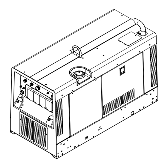
SECTION 12 − PARTS LIST Hardware is common and not available unless listed. Wiring harnesses are listed at the end of parts section. 907 427−3 907 428−5 Figure 12-1. Main Assembly OM-244 620 Page 60... - Page 65 47 48 907 428−4 OM-244 620 Page 61...
- Page 66 Item Dia. Part Mkgs. Description Quantity Figure 12-1. Main Assembly ... . . Figure 12-2 Control Panel ........... .
- Page 67 Item Dia. Part Mkgs. Description Quantity Figure 12-1. Main Assembly (Continued) ....213266 Mount, Engine/Generator Flange Mtg .......
- Page 68 Item Dia. Part Mkgs. Description Quantity Figure 12-1. Main Assembly (Continued) ......Label, Rating Card 907428 (Order By Model And Serial No.) .
- Page 69 Hardware is common and not available unless listed. Wirng harnesses are listed at the end of parts section. 243 761-1B Figure 12-2. Control Panel Item Dia. Part Mkgs. Description Quantity Figure 12-2. Control Panel (Figure 12-1 Item 1) ..
- Page 70 Hardware is common and not available unless listed. Wiring harnesses are listed at the end of parts section. 907 428−6 Figure 12-3. Panel, Front w/Components OM-244 620 Page 66...
- Page 71 Item Dia. Part Mkgs. Description Quantity Figure 12-3. Panel, Front w/Components (Figure 12-1 Item 86 ) ....170391 Conn, Circ Ms Protective Cap Size 20 Nylon .
- Page 72 Hardware is common and not available unless listed. Wiring harnesses are listed at the end of parts section. 907 427-13 Figure 12-4. Generator Item Dia. Part Mkgs. Description Quantity Figure 12-4. Generator (Figure 12-1 Item 61) ..ROTOR .
- Page 73 Hardware is common and not available unless listed. Wiring harnesses are listed at the end of parts section. 246 580-1A Figure 12-5. Weld Control Assembly Item Dia. Part Mkgs. Description Quantity Figure 12-5. Weld Control Assembly 246 580 (Figure 12-1 Item 4) .
- Page 74 Item Dia. Part Mkgs. Description Quantity Figure 12-5. Weld Control Assembly 246 580 (Figure 12-1 Item 4) ... 168829 Transducer, Current 1000a Module Max Open Loop ....
- Page 75 Effective January 1, 2010 (Equipment with a serial number preface of MA or newer) This limited warranty supersedes all previous Miller warranties and is exclusive with no other Warranty Questions? guarantees or warranties expressed or implied. LIMITED WARRANTY − Subject to the terms and conditions 90 Days —...
- Page 76 An Illinois Tool Works Company 1635 West Spencer Street Appleton, WI 54914 USA International Headquarters−USA USA Phone: 920-735-4505 Auto-Attended USA & Canada FAX: 920-735-4134 International FAX: 920-735-4125 For International Locations Visit www.MillerWelds.com © ORIGINAL INSTRUCTIONS − PRINTED IN USA 2010 Miller Electric Mfg. Co.