Table of Contents
Advertisement
Quick Links
Operator's Manual
DH-10 Bench
Register your machine:
www.lincolnelectric.com/register
Authorized Service and Distributor Locator:
www.lincolnelectric.com/locator
Save for future reference
Date Purchased
Code: (ex: 10859)
Serial: (ex: U1060512345)
IM10257
| Issue D ate Apr-2015
© Lincoln Global, Inc. All Rights Reserved.
For use with machines having Code Numbers:
12456
Advertisement
Table of Contents

Related Manuals for Lincoln Electric 12456


Summary of Contents for Lincoln Electric 12456
- Page 1 Operator’s Manual DH-10 Bench For use with machines having Code Numbers: 12456 Register your machine: www.lincolnelectric.com/register Authorized Service and Distributor Locator: www.lincolnelectric.com/locator Save for future reference Date Purchased Code: (ex: 10859) Serial: (ex: U1060512345) IM10257 | Issue D ate Apr-2015...
- Page 2 THANK YOU FOR SELECTING A QUALITY PRODUCT BY KEEP YOUR HEAD OUT OF THE FUMES. DON’T get too close to the arc. LINCOLN ELEC TRIC. Use corrective lenses if necessary to stay a reasonable distance away from the arc. READ and obey the Safety Data PLEASE EXAMINE CARTON AND EQUIPMENT FOR Sheet (SDS) and the warning label DAMAGE IMMEDIATELY...
- Page 3 W117.2-1974. A Free copy of “Arc Welding Safety” booklet E205 is available from the Lincoln Electric Company, 2.d. All welders should use the following procedures in order to 22801 St. Clair Avenue, Cleveland, Ohio 44117-1199.
- Page 4 SAFETY ELECTRIC SHOCK ARC RAYS CAN BURN. CAN KILL. 3.a. The electrode and work (or ground) circuits are 4.a. Use a shield with the proper filter and cover plates to protect your electrically “hot” when the welder is on. Do eyes from sparks and the rays of the arc when welding or not touch these “hot”...
- Page 5 SAFETY WELDING AND CUTTING CYLINDER MAY EXPLODE IF SPARKS CAN CAUSE DAMAGED. FIRE OR EXPLOSION. 7.a. Use only compressed gas cylinders containing the correct shielding gas for the process used 6.a. Remove fire hazards from the welding area. If and properly operating regulators designed for this is not possible, cover them to prevent the welding sparks the gas and pressure used.
-
Page 6: Table Of Contents
TABLE OF CONTENTS Page Installation .......................Section A Technical Specifications .......................A-1 General Description......................A-2 Recommended Processes and Equipment ................A-2 Electrode Routing......................A-3 Wire Drive Speed Range Selection ..................A-3 Control Speed Range Setting ..................A-3 10-Series (DH) Wire Drive Ratio Selection ..............A-3 Wire Feed Drive Roll Kits .....................A-4 Procedure to Install Drive Roll and Guide Tubes ..............A-4 DH Drive Roll Kit Installation ..................A-4 Gun and Cable Assemblies with Standard Connection............A-4... - Page 7 ________________________________________________________________________________ Troubleshooting ....................Section E Safety Precautions .......................E-1 Troubleshooting Procedures ..................E-2 thru E-9 Procedure for Replacing PC Boards ..................E-10 ________________________________________________________________________________ Diagrams ......................Section F Wiring (DH-10 Control) ..................F-1 Wiring (DH Wire Drive) ..................F-2 Dimension Print......................F-3 ________________________________________________________________________ Parts List ......................parts.lincolnelectric.com Content/details may be changed or updated without notice. For most current Instruction Manuals, go to parts.lincolnelectric.com.
-
Page 8: Installation
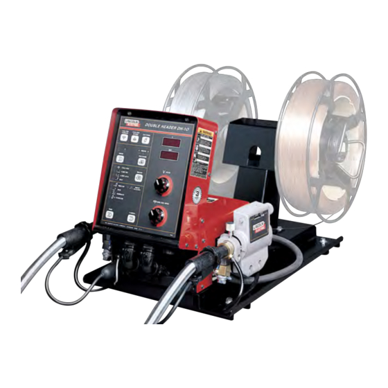
INSTALLATION TECHNICAL SPECIFICATIONS –DH-10 Complete Units or Controls & Heads The K1499-6 DH-10 consists of a control and a double head 10 series wire drive assembly premounted on a platform with two 2” O.D. spindle mountings. Specifications for the units follow: CONTROLS SECTION OF COMPLETE UNITS SPEC.# TYPE... -
Page 9: General Description
Specifications. independently for each head. Recommended power sources are Lincoln Electric Company The units offer 4 independently selectable gun trigger modes for constant voltage power sources with 42 VAC auxiliary power and a each head procedure;... -
Page 10: Electrode Routing
INSTALLATION Electrode Routing The following procedure is for changing ratio of the DH drive: The electrode supply may be either from reels, Readi-Reels, spools, 1) Pull open the Pressure Door. or bulk packaged drums or reels. Observe the following 2) Remove the Phillips head screw retaining the pinion gear to be precautions: changed and remove the gear. -
Page 11: Wire Feed Drive Roll Kits
INSTALLATION WIRE FEED DRIVE ROLL KITS 6) Install each drive roll by pushing over shaft until it butts up against locating shoulder on the drive roll NOTE: The maximum rated solid and cored wire sizes for each shaft. (Do not exceed maximum wire size rating of wire drive head and selected drive ratio is shown on the the wire drive). -
Page 12: Gun Cable Connection With Standard Connection
INSTALLATION Three smoke extraction gun and cable assemblies are *Requires S14927-8 connector hose and an S20591 available, 250 ampere K309, 350 ampere K206 and hose adapter. the 500 ampere K289. All gun cable lengths are 15 ft. (4.5m). These guns will feed electrode sizes .062” Gun Cable Connection with Fast-Mate (1.6mm) to 3/32 (2.4mm) and require the use of the Connection... -
Page 13: Gmaw Shielding Gas
INSTALLATION ELECTRICAL INSTALLATION GMAW Shielding Gas WARNING WARNING CYLINDER may explode if damaged. ELECTRIC SHOCK can kill. • Keep cylinder upright and chained to • Do not touch electrically live parts such as output terminals or internal wiring. support. • When inching with gun trigger, electrode and •... -
Page 14: Work Cable
INSTALLATION Readi-Reel Adapters WORK CABLE K363P Adapts Lincoln Readi-Reel coils of electrode 30 lb. (14 kg) and 22 lb. (10 kg) to a 2" (51 mm) spindle. Durable Connect a work lead of sufficient size and length (per molded plastic one piece construction. Designed for easy the following table) between the proper output termi- loading;... - Page 15 INSTALLATION Using Dual Schedule with Fast-Mate guns on -10 K1558-1 Remote Switch Interface Module, can be Series Feeders used with the DH-10, using a G3041-2 (or higher) Configuration 1 Control Board. K489-9 Dual Schedule Fast-Mate adapter K575-* Magnum 400 DS/FM gun The module provides for user interface connection of (or competitive DS/FM gun) an external switch (flow switch, etc) which must be...
-
Page 16: Operation
OPERATION SAFETY PRECAUTIONS Setting the DIP Switches The DIP switches are each labeled with an “ON” WARNING arrow showing the on direction for each of the 8 indi- vidual switches in each DIP switch (S1 and S2). The ELECTRIC SHOCK can kill. functions of these switches are also labeled and set •... - Page 17 CV-655 / DC-655: (initial factory setting) potentiometer circuit. Limits Pwr Sources The DH-10 is designed to work with the following Lincoln Electric power sources: CV250, CV300-I, CV300, CV400-I, CV400, CV500-I, CV655, DC250, DC-250: DC400, DC600, DC650 PRO, DC1000, Pulse Power Limits...
- Page 18 OPERATION S1 switch 7 ON = 4-Step without current interlock Metric/English Wire Feed Speed Display operation: Selection Limits Pwr Sources The DH-10 Control is set up for Wire Feed Speed dis- play in Metric units (m/min.) or English units (IPM) by setting S1 DIP Switch 6 (Labeled “M”): 1) Closing Trigger initiates gas flow.
-
Page 19: Keypad And Display Operation
OPERATION KEYPAD AND DISPLAY OPERATION Dual procedure settings, including; trigger mode, cold feed speed, Run-in and weld speed and voltage, timers, limits and acceleration are automatically saved for each feeder when power is removed. This feature does not require batteries and when power is restored it will automatically return all settings to the state they were in when power was removed. - Page 20 OPERATION Trigger Mode Selection Display Control Keys Trigger Mode Select key Timer Select key - enables operator to - enables operator to choose burnback, spot or gas timers, as choose mode of operation indicated by the appropriate light. shown by the indicator Pressing the key causes lights to lights.
- Page 21 The DH-10 is designed to work with the following tings is maintained automatically if the Weld voltage setting is Lincoln Electric power sources: CV250, CV300I, changed, so the run-in voltage encoder knob does not need to CV300, CV400-I, CV400, CV500-I, CV655, DC250, be changed to follow the Weld voltage setting.
-
Page 22: Security Modes
OPERATION Security Modes 6. The RUN-IN VOLTS/WFS light will be lit. Set the maximum WFS and voltage limits for procedure B for A security mode is provided to capture and prevent both feeder 1 and feeder 2 using the two encoder changing of procedure settings. -
Page 23: Dual Procedure Remote Control (K1449-5
OPERATION DUAL PROCEDURE REMOTE WARNING CONTROL (K1449-5) Check to be sure the Retaining Spring has fully returned to the locking position and has SECURELY When this option is connected to the DH-10 Control locked the Readi-Reel Cage in place. Retaining Box receptacle, and the Procedure Key selects Spring must rest on the cage, not the welding elec- “REMOTE”... -
Page 24: Feeding Electrode And Brake Adjustment
OPERATION To Mount a 50-60 Lb. (22.7-27.2 kg) Coil: FEEDING ELECTRODE AND BRAKE (Using K1504-1 Coil Reel) (For 50-60 lb Readi- ADJUSTMENT Reels a K438 Readi-Reel Adapter must be used). 1) Turn the Reel or spool until the free end of the The Spindle must be located in the UPPER mounting hole. -
Page 25: Procedure For Setting Angle Of Feedplate
MAKING A WELD required for the procedure being used. 1) Use only a Lincoln Electric recommended constant 12) To stop welding, release the gun trigger and then voltage DC power source compatible with the DH- pull the gun away from the work after the arc goes 10 Wire Feeder. -
Page 26: Wire Reel Changing
B-10 B-10 OPERATION WIRE FEED OVERLOAD PROTECTION WIRE REEL CHANGING The DH-10 has solid-state overload protection of the At the end of a coil, remove the last of the old elec- wire drive motor. If the wire drive motor becomes trode coil from the conductor cable by either pulling it overloaded for an extended period of time, the protec- out at the nozzle end of the gun or by using the follow-... -
Page 27: Explanation Of Prompting And Error Messages
B-11 B-11 OPERATION EXPLANATION OF PROMPTING EEPROM error. Usually occurs at power-up. Indicates one or more of the recalled settings is out AND ERROR MESSAGES of acceptable limits. Press any key to return to nor- mal operation. Be sure to check all voltage, wire feed speed, acceleration and timer settings before you Display Prompt or Error... -
Page 28: Accessories
ACCESSORIES TABLE C.1 – DRIVE ROLL AND GUIDE TUBE KITS Wire Size 4-Roll DH Drive (4-Driven) Solid Steel Electrode 0.023” - 0.025” (0.6 mm) KP1505 - 030S 0.030” (0.8 mm) KP1505 - 030S 0.035” (0.9 mm) KP1505 - 035S 0.040” (1.0 mm) KP1505 - 040S 0.040”... - Page 29 ACCESSORIES INPUT CABLE ASSEMBLIES: (One required per DH-10 Control Box) K683-3 DUAL PROCEDURE SWITCH (One per gun) Kit K1501-10 (Control Cable Only) Consists of a 9-conductor con- includes gun switch, and mountings for Lincoln Innershield and Magnum guns, with 15 ft. (4.5m) control cable and 5-pin trol cable with a 14-pin control cable plug, without electrode plug with two leads to connect to gun trigger.
- Page 30 ACCESSORIES K1500-2 for Magnum 200/300/400 gun with K466-10 con- K498 Magnum 200 FM GMAW gun and cable assemblies nection kit. (Also Tweco 4). are rated for 200 amps 60% duty cycle. (Consult sales specifications for appropriate models) K1500-3 for Magnum 550 gun with K613-7 connection. K534 Magnum 250L FM GMAW gun and cable assemblies (Also Tweco 5).
-
Page 31: Maintenance
MAINTENANCE SAFETY PRECAUTIONS AVOIDING WIRE FEEDING PROBLEMS Wire feeding problems can be avoided by observing the following gun handling and feeder set up proce- WARNING dures: a) Do not kink or pull cable around sharp corners. ELECTRIC SHOCK can kill. •... - Page 32 HOW TO USE TROUBLESHOOTING GUIDE WARNING Service and Repair should only be performed by Lincoln Electric Factory Trained Personnel. Unauthorized repairs performed on this equipment may result in danger to the technician and machine operator and will invalidate your factory warranty. For your safety and to avoid Electrical Shock, please observe all safety notes and precautions detailed throughout this manual.
- Page 33 TROUBLESHOOTING Observe all Safety Guidelines detailed throughout this manual PROBLEMS POSSIBLE RECOMMENDED (SYMPTOMS) CAUSE COURSE OF ACTION Rough wire feeding or wire not 1. Gun cable kinked and/or twisted. feeding, but drive rolls are turning. 2. Wire jammed in gun and cable. 3.
- Page 34 TROUBLESHOOTING Observe all Safety Guidelines detailed throughout this manual PROBLEMS POSSIBLE RECOMMENDED (SYMPTOMS) CAUSE COURSE OF ACTION Poor arc striking with sticking or 1. Improper procedures or techniques. “blast-offs”, weld porosity, narrow and ropy looking bead, or electrode 2. Improper gas shielding. stubbing into the plate while weld- ing.
- Page 35 TROUBLESHOOTING Observe all Safety Guidelines detailed throughout this manual PROBLEMS POSSIBLE RECOMMENDED (SYMPTOMS) CAUSE COURSE OF ACTION Neither side’s drive motor turns 1. Damaged control p.c. board. although arc voltage is present and the gas solenoid is on. No control of wire feed speed on 1.
- Page 36 TROUBLESHOOTING Observe all Safety Guidelines detailed throughout this manual PROBLEMS POSSIBLE RECOMMENDED (SYMPTOMS) CAUSE COURSE OF ACTION Cold feed forward or cold feed 1. The connector from the control reverse buttons on keypad do not p.c. board to the display p.c. work, but motor control otherwise board or the connector from the functions properly for both motors.
- Page 37 TROUBLESHOOTING Observe all Safety Guidelines detailed throughout this manual PROBLEMS POSSIBLE RECOMMENDED (SYMPTOMS) CAUSE COURSE OF ACTION Feeder key does not select head 1 1. The connector from the control or 2, but the head can be selected p.c. board to the display p.c. by pulling the gun trigger.
- Page 38 TROUBLESHOOTING Observe all Safety Guidelines detailed throughout this manual PROBLEMS POSSIBLE RECOMMENDED (SYMPTOMS) CAUSE COURSE OF ACTION One of the knobs changes the dis- 1. The display is in a mode that play, but the other doesn’t. can only use one encoder. 2.
- Page 39 TROUBLESHOOTING Observe all Safety Guidelines detailed throughout this manual PROBLEMS POSSIBLE RECOMMENDED (SYMPTOMS) CAUSE COURSE OF ACTION Displays & LED’s on keypad are 1. The connectors from the control off. The green and red LED’s on p.c. board to the display p.c. the control p.c.
- Page 40 TROUBLESHOOTING Observe all Safety Guidelines detailed throughout this manual PROBLEMS POSSIBLE RECOMMENDED (SYMPTOMS) CAUSE COURSE OF ACTION ‘Er’ is displayed on power up. 1. EEPROM error detected. 2. Damaged control p.c. board. ‘GLP’ is displayed. 1. Ground Loop Protection fault occurred.
- Page 41 If PC board is visibly damaged mechanically, inspect for cause, then remedy before installing a replacement PC board. If there is damage to the PC board or if replacing PC board corrects problem, return it to the local Lincoln Electric Field Service Shop. DH-10...
- Page 42 DIAGRAMS DH-10...
- Page 43 DIAGRAMS DH-10...
- Page 44 DIAGRAMS DIMENSION PRINT DH-10...
- Page 45 NOTES DH-10...
- Page 46 WARNING Do not touch electrically live parts or Keep flammable materials away. Wear eye, ear and body protection. electrode with skin or wet clothing. Insulate yourself from work and AVISO DE ground. Spanish PRECAuCION No toque las partes o los electrodos Mantenga el material combustible Protéjase los ojos, los oídos y el bajo carga con la piel o ropa moja-...
- Page 47 WARNING Keep your head out of fumes. Turn power off before servicing. Do not operate with panel open or Use ventilation or exhaust to guards off. remove fumes from breathing zone. AVISO DE Spanish PRECAuCION Los humos fuera de la zona de res- Desconectar el cable de ali- No operar con panel abierto o piración.
- Page 48 Lincoln Electric for advice or information about their use of our products. We respond to our customers based on the best information in our possession at that time. Lincoln Electric is not in a position to warrant or guarantee such advice, and assumes no liability, with respect to such information or advice.