Table of Contents
Advertisement
Quick Links
Installation
GUIDE
Tuscany Freestanding Dual Fuel Ranges
TVDR3604B, TVDR3602G, CTVDR3604B, CTVDR3602G
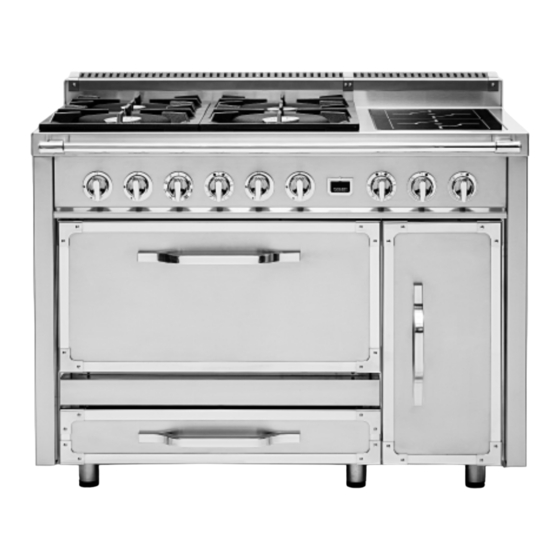
TVDR4806B, TVDR4804G, TVDR4804I, TVDR4802GI, TVDR4804F
CTVDR4806B, CTVDR4804G, CTVDR4804I, CTVDR4802GI, CTVDR4804F
TVDR6608B, TVDR6606G, TVDR6606I, TVDR6606F
CTVDR6608B, CTVDR6606G, CTVDR6606I, CTVDR6606F
Advertisement
Table of Contents

Related Manuals for Viking TVDR3604B


Summary of Contents for Viking TVDR3604B
- Page 1 Installation GUIDE Tuscany Freestanding Dual Fuel Ranges TVDR3604B, TVDR3602G, CTVDR3604B, CTVDR3602G TVDR4806B, TVDR4804G, TVDR4804I, TVDR4802GI, TVDR4804F CTVDR4806B, CTVDR4804G, CTVDR4804I, CTVDR4802GI, CTVDR4804F TVDR6608B, TVDR6606G, TVDR6606I, TVDR6606F CTVDR6608B, CTVDR6606G, CTVDR6606I, CTVDR6606F...
-
Page 2: Table Of Contents
Table of Contents Important Safety Instructions / Warnings ............................. 3 Dimensions /Specifi cations ..................................6 Clearance Dimensions ....................................10 Electrical Requirements .....................................12 Gas Requirements ......................................13 General Information ....................................14 Installation ........................................15 Electrical Connection 3-Wire ................................15 Electrical Connection 4-Wire ................................16 Leveling/Adjustments ...................................18 Anti-Tip Device ......................................20 Final Preparation ......................................22 Service Information .....................................23... -
Page 3: Important Safety Instructions / Warnings
IMPORTANT - Please Read and Follow •Before beginning, please read these instructions completely and carefully. •Do not remove permanently affi xed labels, warnings, or plates from product. This may void the warranty. • All local and national codes and ordinances must be observed. Installation must conform with local codes or in the absence of codes, the National Fuel Gas Code ANSI Z223.1 INFPA54. - Page 4 •The required use of a GFI is normally related to the location of a receptacle with respect to any signifi cant sources of water or moisture. •Viking Range, LLC will NOT warranty any problems resulting from GFI outlets which are not installed properly or do not meet the requirements below.
- Page 5 IMPORTANT - Please Read and Follow DA N GE R WA R NI NG MOVING HAZARD CHEMICAL HAZARD To avoid risk of severe personal To avoid risk of property damage injury; this appliance requires two and/or personal injury or death; or more personnel while handling this appliance is not too be used and moving.
-
Page 6: Dimensions /Specifi Cations
Dimensions / Specifi cations SIDE VIEW 36” W. 35 7/8” (91.1 cm) 30 3/8” (77.2 cm) 27 1/2” (69.9 cm) 39 3/4” (100.9 cm) 35 7/8” 40 1/2” (91.1 cm) (102.9 cm) depending on 36 5/8” leg adjustment (93.0 cm) depending on leg 2”... - Page 7 Dimensions / Specifi cations Surface BTU Rates 36” W /4 Surface Burners 36” W /2 Surface Burners/Griddle 8,500 Nat/ 13,500 Nat/ 13,500 Nat/ 7,700 LP 12,500 LP 12,500 LP 2 kW 20,500 Nat/ 20,500 Nat/ 20,500 Nat/ 18,500 LP 18,500 LP 18,500 LP 48”...
- Page 8 Dimensions / Specifi cations SIDE VIEW 66” W. 30 3/8” (77.2 cm) 27 1/2” (69.9 cm) 39 3/4” (100.9 cm) 66” (167.6 cm) 35 7/8” 40 1/2” (91.1 cm) (102.9 cm) depending on 36 5/8” leg adjustment (93.0 cm) depending on leg adjustment 18 1/4”...
- Page 9 Dimensions / Specifi cations Surface BTU Rates 66” W /8 Surface Burners 8,500 Nat/ 13,500 Nat/ 13,500 Nat/ 13,500 Nat/ 7,700 LP 12,500 LP 12,500 LP 12,500 LP 20,500 Nat/ 20,500 Nat/ 20,500 Nat/ 20,500 Nat/ 18,500 LP 18,500 LP 18,500 LP 18,500 LP 66”...
-
Page 10: Clearance Dimensions
Clearance Dimensions •This range may be installed directly adjacent to existing 36” (91.4 cm) high base cabinets. IMPORTANT: The side panel MUST be 3/8” (.95 cm) above the adjacent base cabinet countertop. This can be accomplished by raising the unit using the adjustment spindles on the legs. •The range CANNOT be installed directly adjacent to sidewalls, tall cabinets, tall appliances, or other side vertical surfaces above 36”... - Page 11 Clearance Dimensions The bottom of a standard hood should be 30” 12” (76.2 cm) min. to 36” (91.4 cm) max. above (30.5 cm) the countertop. This would typically result *optional duct cover in the bottom of the hood being 66” (167.6 cm) to 72”...
-
Page 12: Electrical Requirements
Electrical Requirements WA RN IN G ELECTRICAL SHOCK HAZARD To avoid the risk of electrical shock, personal injury or death; verify electrical power is turned off at the breaker box and gas supply is turned off until the range is installed and ready to operate, installation by an authorized installer only. -
Page 13: Gas Requirements
Gas Requirements Gas Connection The gas supply (service) line must be the same size or greater than the inlet line of the appliance. This range uses a 1/2” (1.3 cm) ID NPT (Sch40) inlet. Sealant on all pipe joints must be resistive to LP gas. The range is designed specifi... -
Page 14: General Information
General Information READ AND FOLLOW ALL WARNING AND CAUTION INFORMATION WHEN INSTALLING THIS APPLIANCE. C AU TI O N • All openings in the wall behind the appliance and in the fl oor under the appliance must be sealed. Avoid any damage to oven vents. The •... -
Page 15: Installation
Installation Electrical Connection 3-Wire WAR NI NG WARN ING ELECTRICAL SHOCK HAZARD ELECTRICAL SHOCK HAZARD To avoid risk of electrical shock, personal injury To avoid risk or electrical shock, personal injury or death; verify your appliance has been properly or death; grounding product to the frame of the grounded in accordance with local codes or in unit may or may not be permitted through your absence of codes, with the National Electrical Code (NEC) ANSI/... -
Page 16: Electrical Connection 4-Wire
Electrical Connection 3-Wire (con’t) Push supply cord toward terminal block to relieve Reattach access door. strain, reattach supply cord strain relief bracket over supply cord. Electrical Connection 4-Wire WAR N IN G WARNI NG ELECTRICAL SHOCK HAZARD ELECTRICAL SHOCK HAZARD To avoid risk of electrical shock, personal injury To avoid risk or electrical shock, personal injury or death;... - Page 17 Electrical Connection 4-Wire (con’t) Feed supply cord up through hole in bottom of Remove grounding screw. Cut-off and discard range back. ground strap. Attach line #1 (red) and line #2 (black) leads to Attach ground lead (green) with ground screw that outside terminal.
-
Page 18: Leveling/Adjustments
Installation Leveling/Adjustments For uneven or sloped fl oors, level unit with metal Measure the four corners in cutout area to verify if shims only, as the adjustment required may exceed fl ooring is level. the thread available in the legs. ”... - Page 19 Installation Leveling/Adjustments (con’t) Set the high corner of range so that the top of side trim is 3/8” (0.95 cm) above countertop. Level range to high corner.
-
Page 20: Anti-Tip Device
Installation Anti-tip Device Installation WARN IN G Your range is shipped standard with two types of anti-tip devices. Type 1 is a wall mount device which can be used for all installation TIPPING HAZARD applications. Type 2 is a fl oor mount device which can be used To reduce the risk of the appliance tipping, it must for all applications other than when the range is installed on a... - Page 21 Installation Floor Mount Installation 8 - 1 8 - 1 8 - 1 ( 2 1 ( 2 1 ( 2 1 ” ” ” Ø Ø Ø ( . 3 ( . 3 ( . 3 8 ” 8 ” 8 ”...
-
Page 22: Final Preparation
Installation Connecting Gas and Electric WARNING GAS LEAK HAZARD To avoid risk of personal injury or death; leak testing of the appliance must be conducted according to the manufacturer’s instructions. Before placing appliance in operation, always check for gas leaks with soapy water solution. •... -
Page 23: Service Information
Clearly describe the problem that you are having. If you are unable to obtain the name of an authorized service agency, or if you continue to have service problems, contact 1-888-845-4641, or write to: VIKING RANGE, LLC PREFERRED SERVICE 111 Front Street... - Page 24 Viking Range, LLC 111 Front Street Greenwood, Mississippi 38930 USA (662) 455-1200 For product information, call 1-888-(845-4641) or visit vikingrange.com F21410C EN (022818)