Table of Contents
Advertisement
Quick Links
Advertisement
Table of Contents

Related Manuals for Sentry Z10000


Summary of Contents for Sentry Z10000
- Page 1 Original Instructions Installation & Maintenance Manual Z10000 Natural Gas Odorization System Patent Pending S-OI-IOM-00087-2 1-15 Sentry equipment Corp 966 Blue Ribbon Circle North • Oconomowoc, WI 53066 USA Tel 262.567.7256 • Fax 262.567.4523 www.sentry-equip.com...
- Page 2 Sentry Equipment Corp. Limit of Liability Sentry Equipment Corp, its employees, agents, and the authors and contributors to this document speci cally disclaim all liabilities and warranties, express or implied (including...
-
Page 3: Table Of Contents
3.6.2 TechView ..................9 3.6.3 External HMI .................9 3.7 Warm Start / Hydraulic Bleed ..............10 4. Mechanical Overview ..................11 4.1 Solenoid Isolation Valve ................11 4.2 Positive Displacement Flow Meter ............11 4.3 Hydraulic Pump ..................12 4.4 Bellows Capsules ..................12 Z10000 Natural Gas Odorization System... - Page 4 5.1 Maintenance cycle ..................14 5.1.1 Pump Removal ................14 5.1.2 Piston Seal Service ..............15 5.2 Pump Odorant Purge ................16 6. Recommended Spare Parts ................17 7. Accessories .....................17 8. Standard Warranty ..................18 9. Factory Assistance ..................20 10. Drawings ......................21 Z10000 Natural Gas Odorization System...
-
Page 5: Safety Information
NOTICE is used to address practices not related to personal injury, but that could result in property damage. NOTE: Information that requires special emphasis. SHALL: is word is understood to be mandatory. SHOULD: is word is understood to be advisory. Z10000 Natural Gas Odorization System... -
Page 6: General Safety Precautions
Prior to installing, removing or maintaining this equipment, ensure that the equipment is isolated from all connecting piping, the equipment is depressurized, the contents have been drained, and the equipment is cool. Z10000 Natural Gas Odorization System... -
Page 7: Warning Labels
5. Conduit per Class I, Division 2 Standards Storage Tank (This tank has been pressure tested at the factory) Important procedure to follow before filling tank with odorant: Evacuate air and pressure test prior to filling tank with odorant. Z10000 Natural Gas Odorization System... - Page 8 This page intentionally left blank. Z10000 Natural Gas Odorization System...
-
Page 9: Specifications
Altitude Range Odorizer: 0–2000 ft HMI: 0–2000 ft *at injection rate of 0.5# odorant/mmscf TechView is a freeware program from Emerson Process Management † configured by Sentry Equipment Corp for use with the Z10000 odorizer Z10000 Natural Gas Odorization System... -
Page 10: Overview
Every action is intuitive and predictable. The Z10000 is a proven system, working reliably in some of the most sensitive areas imaginable, including major cities that experience blizzard conditions year after year. Remote locations are also accommodated as virtually everything can be taken care of via communications features. -
Page 11: System Components
Overview 2.4 System Components There are three major components to the Z10000 Natural Gas Odorization System: • Z10000 Injector • System controller • Odorant storage vessel 2.4.1 Z10000 Injector 2.4.2 System Controller The System Controller interfaces with the Z10000 injector, precision odorant flow measurement and gas flow information, local interface, remote interface, etc., to maintain a constant... -
Page 12: Odorant Storage Vessel
30 psi. Regulated pipeline gas or nitrogen is A pressure regulator/ commonly used. Odorant moves from the vessel probe through relief device must be the filter to the isolation valve (that automatically closes with supplied by the customer. loss of pipeline pressure). Z10000 Natural Gas Odorization System... -
Page 13: Installation
3.1 Site Requirements 3.1.1 Unit Location If possible install the Z10000 at or below the Odorant Storage Vessel. This allows further reduction of blanket pressures on the odorant storage tank. Â Note: 3.1.2 Blanket Gas... -
Page 14: Wiring Termination
3.4.5 I/O Signal Verification The TechView I/O page allows verification of I/O signals to the Z10000. The status of DI and DO pins can be seen and verified. See the image below for an example of the I/O screen. Z10000 Natural Gas Odorization System... - Page 15 Usage (DO3), Alarm (DO4), Gas Flow (HSC2 or AI1), and in some cases Bulk Tanks (AI2). Others are verified in the factory and should not be modified in the field except under advice from technical support. Z10000 Natural Gas Odorization System...
-
Page 16: External Hmi (Optional)
MJ2 located on the right side of the HMI controller. 7. Run the ethernet cable though code applicable conduit from the external HMI to the Z10000 enclosure and connect the other end to the RJ45 patch panel located inside the enclosure. -
Page 17: Unit Configuration
(TechView) • configuration using the external HMI 3.6.1 Remote Configuration To have the Z10000 configured remotely by a Sentry Equipment technician, please contact Sentry Equipment a minimum of one week prior to startup. The following information is required for remote configuration: • Planned startup date... -
Page 18: Warm Start / Hydraulic Bleed
7. Continue to run, or repeat steps 4–7 until efficiency is consistently over 85% (0.85), then disable pump prime. 8. Move the Inject/Purge valve (KK) to the “Inject” position 9. Verify solenoid override is in auto (from leak testing). 10. Turn Unit on. Z10000 Natural Gas Odorization System... -
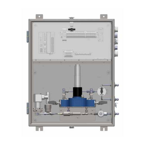
Page 19: Mechanical Overview
Pump Assembly Temperature Transmitter 4.1 Solenoid Isolation Valve The solenoid isolation valve on the Z10000 is an electric solenoid valve. When the solenoid is electrically charged, it opens and allows the odorant to flow. 4.2 Positive Displacement Flow Meter The positive displacement flow meter is... -
Page 20: Hydraulic Pump
The motor resumes pumping once head pressure of 10 psig is restored, opening the pressure switch. 4.6 Temperature Transmitter The Temperature transmitter measures the temperature of the incoming odorant, providing compensation for temperature induced density changes. Z10000 Natural Gas Odorization System... -
Page 21: Control Boards
Mechanical Overview 4.7 Control Boards Power Supply Board CPU Board Mixed I/O Board Z10000 Natural Gas Odorization System... -
Page 22: Hydraulic Pump Maintenance
6. The pump body can now be pulled out of the mechatronic enclosure. Note that hydraulic fluid can leak out of the pump body at this point; take care to minimize spills and drips of the fluid. Z10000 Natural Gas Odorization System... -
Page 23: Piston Seal Service
12. Fill the pump body with Hydraulic fluid #41 (6- 05488R), moving the piston back and forth, priming each chamber. This results in some hydraulic fluid being pumped out of each Piston Chamber outlet fitting (T). Z10000 Natural Gas Odorization System... -
Page 24: Pump Odorant Purge
5.2 Pump Odorant Purge In some cases, it may be necessary to drain and purge all odorant from the Z10000 assembly and back into the bulk tank. Do not send high pressure purge gas (either nitrogen or pipeline gas) through the Z10000. -
Page 25: Recommended Spare Parts
7. Accessories Item Part Number 6-05568E Heater * 6-05568D Wireless Modem 6-05568C Odorant Visual Indicator 7-04733A External HMI 7-04578K * Note: For heater accessory customer to provide fused disconnect sized in accordance with local code. Z10000 Natural Gas Odorization System... -
Page 26: Standard Warranty
Seller’s receiving written notice of any alleged defect within 10 days a er its discovery and, at Seller’s option, return of such product to Seller, FOB Sentry’s factory or provision of evidence (e.g., photographs) of such defect satisfactory to Seller. - Page 27 Sentry factory may accept the entire claim, a part of the claim or none of the claim if our inspection of returned parts proves the failure was for reasons other than defective material or factory workmanship.
-
Page 28: Factory Assistance
Please do not return any equipment before discussing your application problem with a Sentry representative and obtaining a Return Authorization. Sentry Equipment Corp has a complete sta of trained Service Department associates to assist customers with any problems. Please call Sentry at 262.567.7256 (Fax: 262.567.4523) to request a service representative. -
Page 29: Drawings
Drawings 10. Drawings Z10000 Natural Gas Odorization System...