Table of Contents
Advertisement
Quick Links
Advertisement
Chapters
Table of Contents

Related Manuals for Sentry ST520


Summary of Contents for Sentry ST520
- Page 3 520/ 522 Chroma Meter Instruction Manual 使用說明書...
-
Page 4: Table Of Contents
Table Content 1. Product Introduction ------------------------------ 1 1-1 Features ------------------------------------------- 1 1-2 Applications --------------------------------------- 1 2. Safety Information --------------------------------- 2 2-1 Safety Symbols ----------------------------------2 2-2 Warning ----------------------------------------- 3 3. Specifications ------------------------------------- 5 4. General Descriptions --------------------------- 6 4-1 LCD and Control Panel --------------------- 6 4-2 Rear ---------------------------------------------- 7 4-3 Probe ------------------------------------------- 7 4-4 Battery Change -------------------------------- 8... -
Page 5: Product Introduction
Product Introduction Thank you for purchasing the Chroma Meter. Read through this instruction manual before operating the meter. Please also store and retain this instruction manual for future reference. 1-1 Features Precision instrument for light illuminance and color coordinate. ... -
Page 6: Safety Information
Film and television. Projection halls. Art galleries. Warehouses. Museums. Stadiums. Arenas. Safety Information Read the following safety information carefully before attempting to operate or service the meter. Only qualified personnel should perform repairs. 2-1 Safety Symbols CE Certification. -
Page 7: Warning
Restrict to use of six substances within electrical and electronic equipment (EEE), thereby contributing to the protection of human health and the environment. REACH (SVHC) The device of used materials content no following substances that list of proposed REACH substances of very high concern. - Page 8 When using is complete, close the receptor cover. Be aware the accumulation of irradiations would cause the sensor continue to age. Please keep away the light source and cover with the cap when the unit is not in use. ...
-
Page 9: Specifications
3. Specifications Model SPC(Silicon Photocell) Sensor Element FL (Fluorescent light source) Measuring Light Sources General Light Source INC (Incandescent light source) Selection LED (LED light source) Illuminance:Ev(lx or fcd) Color Coordinate: (x, y),(u', v') (CIE 1960) Correlated Color Temperature:CT, ⊿uv Measuring Function Color Difference:... -
Page 10: General Descriptions
4. General Descriptions 4-1 LCD and Control Panel A. Data Hold Symbol G. Illuminance Unit (lx or fcd) B. SET Function Symbol Symbol C. Low Battery Symbol H. Primary Reading D. Measuring Symbols of I. Color Temperature Unit (K) Primary Reading Symbol E. -
Page 11: Rear
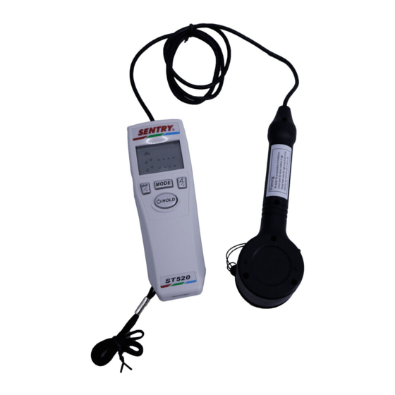
4-2 Rear Q. Tripod Socket R. Battery Cover S. Magnet Position T. Anti-slippery Pad 4-3 Probe U. Receptor Head V. Receptor Cover W.Grip... -
Page 12: Battery Change
4-4 Battery Change The meter is powered by a 9V battery. When the symbol appears, the battery voltage drops below the level for reliable operation, the user has to replace a new battery. Turn the meter off first, open the battery cover on the back and replace the battery in the battery compartment. -
Page 13: Operation Instruction
5. Operation Instruction 5-1 Main Function Power ON/OFF Press and hold the Power button for 2 seconds to turn the meter on. Then all of symbols will appear for 2 seconds on the LCD. After power-on, the meter will measure and show the readings on the LCD continuously. - Page 14 Example: Switch FL light source to INC light source. FL Light source Hold for 3 Secs. INC Light source Data Hold During measuring, press the HOLD button once to hold the measured values and the HOLD symbol will appear on the LCD. Press HOLD button again to return to measure.
- Page 15 Measuring Modes Color measurement and color difference are switchable by pressing MODE and button. Both of them also have 3 modes to select: ‧Color Measurement: 1. Ev, x, y (Illuminance, Color coordinate) 2. Ev, u', v' (Illuminance, Color coordinate, CIE1960) 3.
- Page 16 Measuring Modes Diagram MODE ⊿uv Color Measurement ⊿ MODE Color Difference ⊿Ev ⊿Ev ⊿Ev ⊿ ⊿ x ⊿ u' (522) ⊿u'v' ⊿ y ⊿ v' ⊿...
- Page 17 ‧LCD Display in the Color Measurement: 1. Ev, x, y (Illuminance, Color coordinate) 2. Ev, u', v' (Illuminance, Color coordinate, CIE1960) 3. Ev, CT, ⊿uv (Illuminance, Color temperature)...
- Page 18 ‧LCD Display in the Color Difference: 1. ⊿Ev, ⊿x, ⊿y(Color difference of Illuminance and Color coordinate) 2. ⊿Ev, ⊿u', ⊿v'(Color difference of Illuminance and Color coordinate, CIE1960) 3. ⊿Ev, ⊿CT(522), ⊿u'v'(Color difference of Illuminance and Color temperature)
-
Page 19: Set Function
5-2 SET Function Color Difference : This function allows user to set certain reference values ( Ev (522) ) to , u' , v' ref, compare with the target color. Set the Reference Value You can select one of these color difference modes to set: 1. - Page 20 Set the reference values in either of two methods: 5-2-1. Using the measured values and adjust it manually as the reference values. 5-2-2. Using the previous values stored in memory and adjusts it manually as the reference values. The difference between method 5-2-1 and 5-2-2 is whether the Data Hold was enabled before entering the set mode.(See diagram 5-2b)...
-
Page 21: Using The Measured Values
5-2-1 Using the Measured Values a.Select the(Ev, x, y)mode first and measure a light source. 1.Press the HOLD button to hold these values that you want to use as your reference values. 2.Press the button once to toggle the color difference mode. - Page 22 a.Using the measured values to set the reference values of (⊿Ev, ⊿x, ⊿y)mode. MODE MODE...
- Page 23 b.Using the measured values to set the reference values of (⊿Ev, ⊿u', ⊿v')mode. MODE MODE...
- Page 24 c.Using the measured values to set the reference values of (⊿Ev, ⊿CT, ⊿u’v’)mode.(522) MODE...
-
Page 25: Using The Previous Values
5-2-2 Using the previous values stored in memory a.Select the color different(⊿Ev, ⊿x, ⊿y)mode directly. 1.Press the button and hold for 3 seconds to toggle set reference values mode without Data Hold. 2.The SET symbol will appear and the Ev symbol will flash on the LCD. - Page 26 a. Using the previous values to set the reference values of (⊿Ev, ⊿x, ⊿y)mode. MODE MODE...
- Page 27 b.Using the previous values to set the reference values of (⊿Ev, ⊿u', ⊿v')mode. MODE MODE...
- Page 28 c.Using the previous values to set the reference values of (⊿Ev, ⊿CT, ⊿u’v’)mode.(522) MODE Zero the Reference Values of Color Difference Close the receptor cover and the(Ev, x, y ,Ev, u', v' or EV, CT) measured values will show zero. Then repeat the section 5-2-1 that using the measured values to zero the reference value.
-
Page 29: Maintenance
6. Maintenance Clean the Receptor Head: Blow off loose particles using clean compressed air. Gently brush remaining debris sway with a camel's hair brush. Carefully wipe the surface with a cotton swab. The swab may be moistened with some water. Clean the Housing:... - Page 30 520/522 色彩照度計 Instruction Manual Instruction Manual Instruction Manual 使用說明書...
- Page 31 項次 1.產品簡介 -------------------------------- 1 1-1 特色---------------------------------- 1 1-2 適用範圍 ----------------------------- 1 2.安全需知 -------------------------------- 2 2-1 安全標章 ----------------------------- 2 2-2 注意要項------------------------------ 3 3.規格 ------------------------------------ 4 4.一般描述 -------------------------------- 5 4-1 LCD 與控制面板 ----------------------- 5 4-2 背面外觀 ----------------------------- 6 4-3 探測棒外觀 --------------------------- 6 4-4 電池替換...
-
Page 32: 產品簡介
1.產品簡介 感謝您購買本公司色彩照度計。請詳閱此手冊,再依照手冊 操作儀器。並請保有手冊,以做為未來操作時的依據。 1-1 特色 光照度與色座標量測的精密儀器。 符合國際照明委員會(CIE)的明視覺光譜響應。 照度量測。 色溫及相對色溫量測。 色座標量測。 使用者可自定義色差模式的參考值。 可選擇量測的光源種類。(522) 低電量指示。 自動關機。 自動背光 LCD 與三排顯示。 資料鎖定功能。 照度(Lux)或燭光(foot-candle)單位選擇。 磁鐵固定。 三腳架固定孔。 1-2 適用範圍 彩色LED照明。 室內裝潢照明。 ... -
Page 33: 安全標章
電影與電視。 投影廳。 藝術畫廊。 倉庫。 博物館。 圖書館。 體育場。 戲院。 學校。 活動場所。 辦公室。 2.安全須知 欲使用或保養本儀器前,請仔細閱讀以下安全須知。並且只有合 格認證的工程師才可對本產品進行維修。 2-1 安全標章 CE 認證 本儀器符合下列標準: EN61326:實驗室量測或控制設備電磁相容檢測。 IEC61000-4-2:靜電放電耐受檢測。 IEC61000-4-3:輻射耐受檢測。 IEC61000-4-8:電源頻率磁場耐受檢測。 當外來電磁波頻率在180~500MHz附近且強度達到3V/m時,儀器可 能無法達到產品所要求的規格。... -
Page 34: 注意要項
規範電器電子儀器(EEE)產品所禁用的6種物質,以確保 人體健康及環境安全。 REACH(SVHC) 謹遵守REACH管理規範,本儀器不含高度關切物質(SVHC)。 本產品不能當作一般垃圾處理。提倡回收可重複利用的 材料元件,並改善企業環境績效,請按照所在國家的法 規妥善處理廢棄產品。 2-2 注意要項 確實遵守下列要點以避免損害: 使用儀器前請先仔細閱讀使用手冊以確保安全,並正確地使 用。如有需要請反覆閱讀。 請勿將儀器浸泡在水裡。 請勿拆解或修改儀器。 假使儀器故障,請勿自行嘗試修復,只有合格認證的工程師才 能進行維修。 請勿按壓或敲擊LCD與接收探頭。 請勿在易燃或鄰近火源的地方使用儀器。 請勿在超出此溫濕度範圍的環境使用儀器:0℃~50℃,小於80% RH。 使用完畢請闔上接收探頭蓋子。 請了解在長時間照射下感測器會逐漸老化。 假使儀器長時間未使用請移除電池並闔上接收探頭蓋子。 請勿使用有機溶劑清潔儀器(如稀釋劑、苯等)。... - Page 35 3.規格 型號 感測元件 矽光二極體 FL(螢光光源) INC(白織光源) 量測光源種類 通用型光源 LED(LED 光源) 照度:Ev(lx 或 fcd) 色座標: (x, y),(u', v') (CIE 1960) 相對色溫:CT, ⊿uv 量測功能 色差: (⊿Ev,⊿x,⊿y),(⊿Ev,⊿u',⊿v') (⊿Ev,⊿u'v'),(可設一組參考值) 相對色溫差值量測 ⊿ 無 有 Ev:0~80000 lx(0~7432 fcd) 量測範圍 CT:99990 K 最大 精準度 Ev:± (3%+2) (3000 lx, 標準 A 光源) (在...
-
Page 36: Lcd 與控制面板
※ 在以下的說明中,以(522) 註記代表 522 專屬之功能。 4.一般說明 4-1 LCD 與控制面板 A.資料鎖定符號 G.照度單位流明(lx)或燭光 B.設定功能符號 (fcd)符號 C.低電量指示符號 H.第一排量測讀值 D.第一排讀值的量測符號 I.色溫單位(K)符號 E.第二排讀值的量測符號 J.第二排量測讀值 F.第三排讀值的量測符號 K.量測光源種類(FL,INC 或 LED)(522)符號 L.第三排量測讀值 M.單位切換/向下鍵 O.⊿(色差)/向上鍵 N.模式切換鍵 P.電源與資料鎖定鍵... -
Page 37: 背面外觀
4-2 背面外觀 Q.三腳架固定孔 R.電池蓋 S.磁鐵固定位置 T.止滑墊 4-3 探測棒外觀 U.接收探頭 V.接收探頭蓋 W.握把... -
Page 38: 電池替換
4-4 電池替換 本儀表使用9V電池供電。當低電量 符號亮起,表示電池低 於正常操作電壓,使用者必須更換新電池。先打開後面的電池蓋, 然後更換電池槽內的電池,完成後確實蓋好電池蓋。 步驟一 步驟二... -
Page 39: 操作說明
5.操作說明 5-1 主功能 電源開關與量測 按壓住電源鍵2秒開啟電源,LCD上所有符號會顯示2秒,之後儀表 將連續讀取待測光源之量測值並且顯示在LCD上。當使用者要關閉 儀表時,請重覆按壓住電源鍵2秒關機。 量測單位 按下 鍵可切換照度(Ev)單位:流明(lx)或燭光(fcd)。 量測光源種類選擇(522) 在量測前,使用者宜先選擇待測光源之類別,提升色彩及照度之 量測值之精確性。選擇光源之操作步驟如下: 在 CT 及⊿CT 畫面顯示時, 按壓住 鍵 3 秒可依序切換量測的 光源種類,共有三種光源可以選擇,分別為:FL(螢光光源)、INC(白 熾光源)、 LED(LED 光源)。量測時選擇正確對應的光源種類,可得 到較精確 CT(色溫)數值。 注意:若在量測時,CT 數值顯示為”----”,代表此待測物的 CT 數值超出該光源種類的設定範圍,請切換不同光源種類進行量測。... - Page 40 如下圖所示:由 FL 光源切換到 INC 光源。 FL 光源 按 3 秒 INC 光源 資料鎖定 量測期間,按下HOLD鍵可鎖定量測值,且HOLD符號會顯示在LCD 上,再按下HOLD鍵則返回連續量測。...
- Page 41 量測模式 本儀表提供兩種量測:色彩與色差量測。 色彩與色差量測可透過 MODE 鍵和 (色差)鍵互相切換。 兩種量測也都有 3 種模式可選擇: ‧色彩量測: 1. Ev, x, y (照度,色座標) 2. Ev, u', v' (照度,色座標,CIE1960) 3. Ev, CT, ⊿uv (照度,色溫) 色彩量測請按下 MODE 鍵切換。 ‧色差量測: 1. ⊿Ev, ⊿x, ⊿y (照度差值,色座標差值) 2. ⊿Ev, ⊿u', ⊿v'(照度差值,色座標差值,CIE1960) 3. ⊿Ev, ⊿CT(522), ⊿u'v'(照度差值,色溫差值) 此功能提供用戶對於多個光源測量或檢查照度,顏色坐標顏色和...
- Page 42 量測模式圖 MODE ⊿uv 色彩量測 ⊿ MODE 色差量測 ⊿Ev ⊿Ev ⊿Ev ⊿ ⊿ x ⊿ u' (522) ⊿ y ⊿ v' ⊿u'v' ⊿...
- Page 43 ‧色彩量測下,LCD 顯示畫面: 1.Ev, x, y (照度,色座標) 2.Ev, u', v' (照度,色座標 CIE1960) 3.Ev, CT, ⊿uv (照度,色溫)...
- Page 44 ‧色差量測下,LCD 顯示畫面: 1.⊿Ev, ⊿x, ⊿y (照度差值,色座標差值) 2.⊿Ev, ⊿u', ⊿v' (照度差值,色座標差值 CIE1960) 3.⊿Ev, ⊿CT(522), ⊿u'v' (照度差值,色溫差值)...
-
Page 45: 設定功能
5-2 設定功能 色差量測:本儀表提供色彩的比對功能,使用者可以設定一組特 定的色彩參考值(Ev , u' , v' , CT 參考值 參考值 參考值 參考值 參考值 (522)),來比較與待量測光源之色彩的差異。 參考值 設定參考值 可選用其中的一種色差模式進去做設定: 1. ⊿Ev , ⊿x , ⊿y 2. ⊿Ev , ⊿u', ⊿v' 3. ⊿Ev , ⊿CT(522), ⊿u'v' 在色差模式下,按壓住 (色差)鍵 3 秒可進入設定。 (參照圖 5-2a) 色差量測... - Page 46 使用下列兩種方式中任一來設定參考值: 5-2-1.使用量測值,然後再手動調整該值當參考值。 5-2-2.使用原先儲存值,然後再手動調整該值當參考值。 上述兩種方式的差異在,進入設定模式前,資料鎖定 HOLD 是否有 開啟。(參照圖 5-2b) 備註:(色差 = 量測值 參考值 ) – 範例: ⊿Ev = Ev – Ev 量測值 參考值 ⊿x – x 量測值 參考值 ⊿y – y 量測值 參考值 ⊿u' = u' – u' 量測值 參考值 ⊿v' = –...
-
Page 47: 使用量測值設定參考值
5-2-1 使用量測值設定參考值 a.先選擇(Ev, x, y)模式並量測一個光源。 1.按下HOLD鍵鎖定您認為穩定的量測值當參考值使用。 2.按下 (色差)鍵一下切換到色差量測。 3.再按壓住 (色差)鍵3秒進入設定參考值模式。LCD上SET 符號會顯現,Ev符號會閃爍。設定模式下,Ev 預設值會 參考值 顯示先前鎖定的量測值。 4.按下 鍵或 鍵可調整Ev 。 參考值 5.按下MODE鍵確定,至下個參考值(x )。 參考值 6.重複步驟4,再去調整參考值x 和y 。 參考值 參考值 7.再次按下MODE鍵可返回色差量測。 → → x → → y → →色差模式 MODE MODE MODE 參考值 參考值... - Page 48 a.使用量測值去設定(⊿Ev, ⊿x, ⊿y)模式下的參考值 MODE MODE...
- Page 49 b.使用量測值去設定(⊿Ev, ⊿u', ⊿v')模式下的參考值 MODE MODE...
- Page 50 c.使用量測值去設定(⊿Ev, ⊿CT, ⊿u’v’)模式下的參考值(522) MODE...
-
Page 51: 使用原先儲存值設定參考值
5-2-2 使用原先儲存值設定參考值 a.直接選擇色差量測(⊿Ev, ⊿x, ⊿y)模式。 1.在無資料鎖定下,按壓住 (色差)鍵 3秒進入設定模式。 2.在LCD上SET符號會顯現,Ev符號會閃爍。設定模式下,Ev 參考值 預設值會顯示原先儲存值。 3.按下 鍵或 鍵可調整Ev 。 參考值 4.按下MODE鍵至下個參考值(x )。 參考值 5.重複步驟3,去調整參考值x 和y 。 參考值 參考值 6.再次按下MODE鍵可返回色差量測。 → → x → → y → →色差模式 MODE MODE MODE 參考值 參考值 參考值 b.選擇(⊿Ev, ⊿u', ⊿v')模式並重覆步驟1~6即可設定u', v' 參考值。... - Page 52 a.使用原先儲存值去設定(⊿Ev, ⊿x, ⊿y)模式下的參考值 MODE MODE...
- Page 53 b.使用原先儲存值去設定(⊿Ev, ⊿u', ⊿v')模式下的參考值 MODE MODE MODE MODE...
- Page 54 c.使用原先儲存值去設定(⊿Ev, ⊿CT, ⊿u’v’)模式下的參考值 (522) MODE...
-
Page 55: 基本保養
色差參考值的歸零 闔上接收探頭的蓋子,(Ev, x, y 、Ev, u', v'、Ev, CT)皆會 顯示零,然後重覆 5-2-1 章節,使用量測值設定,就能將參考值 歸零。 6.基本保養 清潔接收探頭: 用乾淨的壓縮空氣吹掉表面塵粒,再用軟刷輕輕的刷去剩餘碎 屑,並小心地用棉布擦拭,棉布可沾些水幫助清潔。 清潔外殼: 清潔儀器時,可用沾有肥皂水的海綿或軟布擦拭。 注意: 請勿使用有機溶劑清潔儀表或接收探頭(如稀釋劑、苯等)。 假使儀表長時間未使用,請移除電池並蓋好接收探頭蓋子。... - Page 56 Note...
- Page 57 Note...
- Page 58 Ver.01 13/Sep.
- Page 60 SENTRY OPTRONICS CORP. 3F., No.122, Sec.1, Sanmin Rd., Banqiao Dist., New Taipei City 220, Taiwan (R.O.C.) TEL:886-2-2956-8198 FAX:886-2-2956-7662 Http://www.sentrytek.com.tw PA05-000052X-01 Ver.01 13/Sep.